
11.2: Galvanic Cells
- Page ID
- 522546

\( \newcommand{\vecs}[1]{\overset { \scriptstyle \rightharpoonup} {\mathbf{#1}} } \)
\( \newcommand{\vecd}[1]{\overset{-\!-\!\rightharpoonup}{\vphantom{a}\smash {#1}}} \)
\( \newcommand{\dsum}{\displaystyle\sum\limits} \)
\( \newcommand{\dint}{\displaystyle\int\limits} \)
\( \newcommand{\dlim}{\displaystyle\lim\limits} \)
\( \newcommand{\id}{\mathrm{id}}\) \( \newcommand{\Span}{\mathrm{span}}\)
( \newcommand{\kernel}{\mathrm{null}\,}\) \( \newcommand{\range}{\mathrm{range}\,}\)
\( \newcommand{\RealPart}{\mathrm{Re}}\) \( \newcommand{\ImaginaryPart}{\mathrm{Im}}\)
\( \newcommand{\Argument}{\mathrm{Arg}}\) \( \newcommand{\norm}[1]{\| #1 \|}\)
\( \newcommand{\inner}[2]{\langle #1, #2 \rangle}\)
\( \newcommand{\Span}{\mathrm{span}}\)
\( \newcommand{\id}{\mathrm{id}}\)
\( \newcommand{\Span}{\mathrm{span}}\)
\( \newcommand{\kernel}{\mathrm{null}\,}\)
\( \newcommand{\range}{\mathrm{range}\,}\)
\( \newcommand{\RealPart}{\mathrm{Re}}\)
\( \newcommand{\ImaginaryPart}{\mathrm{Im}}\)
\( \newcommand{\Argument}{\mathrm{Arg}}\)
\( \newcommand{\norm}[1]{\| #1 \|}\)
\( \newcommand{\inner}[2]{\langle #1, #2 \rangle}\)
\( \newcommand{\Span}{\mathrm{span}}\) \( \newcommand{\AA}{\unicode[.8,0]{x212B}}\)
\( \newcommand{\vectorA}[1]{\vec{#1}} % arrow\)
\( \newcommand{\vectorAt}[1]{\vec{\text{#1}}} % arrow\)
\( \newcommand{\vectorB}[1]{\overset { \scriptstyle \rightharpoonup} {\mathbf{#1}} } \)
\( \newcommand{\vectorC}[1]{\textbf{#1}} \)
\( \newcommand{\vectorD}[1]{\overrightarrow{#1}} \)
\( \newcommand{\vectorDt}[1]{\overrightarrow{\text{#1}}} \)
\( \newcommand{\vectE}[1]{\overset{-\!-\!\rightharpoonup}{\vphantom{a}\smash{\mathbf {#1}}}} \)
\( \newcommand{\vecs}[1]{\overset { \scriptstyle \rightharpoonup} {\mathbf{#1}} } \)
\(\newcommand{\longvect}{\overrightarrow}\)
\( \newcommand{\vecd}[1]{\overset{-\!-\!\rightharpoonup}{\vphantom{a}\smash {#1}}} \)
\(\newcommand{\avec}{\mathbf a}\) \(\newcommand{\bvec}{\mathbf b}\) \(\newcommand{\cvec}{\mathbf c}\) \(\newcommand{\dvec}{\mathbf d}\) \(\newcommand{\dtil}{\widetilde{\mathbf d}}\) \(\newcommand{\evec}{\mathbf e}\) \(\newcommand{\fvec}{\mathbf f}\) \(\newcommand{\nvec}{\mathbf n}\) \(\newcommand{\pvec}{\mathbf p}\) \(\newcommand{\qvec}{\mathbf q}\) \(\newcommand{\svec}{\mathbf s}\) \(\newcommand{\tvec}{\mathbf t}\) \(\newcommand{\uvec}{\mathbf u}\) \(\newcommand{\vvec}{\mathbf v}\) \(\newcommand{\wvec}{\mathbf w}\) \(\newcommand{\xvec}{\mathbf x}\) \(\newcommand{\yvec}{\mathbf y}\) \(\newcommand{\zvec}{\mathbf z}\) \(\newcommand{\rvec}{\mathbf r}\) \(\newcommand{\mvec}{\mathbf m}\) \(\newcommand{\zerovec}{\mathbf 0}\) \(\newcommand{\onevec}{\mathbf 1}\) \(\newcommand{\real}{\mathbb R}\) \(\newcommand{\twovec}[2]{\left[\begin{array}{r}#1 \\ #2 \end{array}\right]}\) \(\newcommand{\ctwovec}[2]{\left[\begin{array}{c}#1 \\ #2 \end{array}\right]}\) \(\newcommand{\threevec}[3]{\left[\begin{array}{r}#1 \\ #2 \\ #3 \end{array}\right]}\) \(\newcommand{\cthreevec}[3]{\left[\begin{array}{c}#1 \\ #2 \\ #3 \end{array}\right]}\) \(\newcommand{\fourvec}[4]{\left[\begin{array}{r}#1 \\ #2 \\ #3 \\ #4 \end{array}\right]}\) \(\newcommand{\cfourvec}[4]{\left[\begin{array}{c}#1 \\ #2 \\ #3 \\ #4 \end{array}\right]}\) \(\newcommand{\fivevec}[5]{\left[\begin{array}{r}#1 \\ #2 \\ #3 \\ #4 \\ #5 \\ \end{array}\right]}\) \(\newcommand{\cfivevec}[5]{\left[\begin{array}{c}#1 \\ #2 \\ #3 \\ #4 \\ #5 \\ \end{array}\right]}\) \(\newcommand{\mattwo}[4]{\left[\begin{array}{rr}#1 \amp #2 \\ #3 \amp #4 \\ \end{array}\right]}\) \(\newcommand{\laspan}[1]{\text{Span}\{#1\}}\) \(\newcommand{\bcal}{\cal B}\) \(\newcommand{\ccal}{\cal C}\) \(\newcommand{\scal}{\cal S}\) \(\newcommand{\wcal}{\cal W}\) \(\newcommand{\ecal}{\cal E}\) \(\newcommand{\coords}[2]{\left\{#1\right\}_{#2}}\) \(\newcommand{\gray}[1]{\color{gray}{#1}}\) \(\newcommand{\lgray}[1]{\color{lightgray}{#1}}\) \(\newcommand{\rank}{\operatorname{rank}}\) \(\newcommand{\row}{\text{Row}}\) \(\newcommand{\col}{\text{Col}}\) \(\renewcommand{\row}{\text{Row}}\) \(\newcommand{\nul}{\text{Nul}}\) \(\newcommand{\var}{\text{Var}}\) \(\newcommand{\corr}{\text{corr}}\) \(\newcommand{\len}[1]{\left|#1\right|}\) \(\newcommand{\bbar}{\overline{\bvec}}\) \(\newcommand{\bhat}{\widehat{\bvec}}\) \(\newcommand{\bperp}{\bvec^\perp}\) \(\newcommand{\xhat}{\widehat{\xvec}}\) \(\newcommand{\vhat}{\widehat{\vvec}}\) \(\newcommand{\uhat}{\widehat{\uvec}}\) \(\newcommand{\what}{\widehat{\wvec}}\) \(\newcommand{\Sighat}{\widehat{\Sigma}}\) \(\newcommand{\lt}{<}\) \(\newcommand{\gt}{>}\) \(\newcommand{\amp}{&}\) \(\definecolor{fillinmathshade}{gray}{0.9}\)- Identify the components of a galvanic cell and their roles in converting chemical energy to electrical energy.
- Write balanced half-reactions and the overall reaction for a galvanic cell.
- Use shorthand (cell) notation to represent a galvanic cell.
Galvanic cells, also called voltaic cells, are devices that turn chemical energy into electrical energy using spontaneous redox reactions. These cells power everyday items like batteries and help us understand how chemical reactions can produce useful electricity. To see how this works, we often separate the overall redox reaction into two half-reactions: one for oxidation and one for reduction. This makes it easier to balance the equations and see which chemical species are gaining or losing electrons during the process.
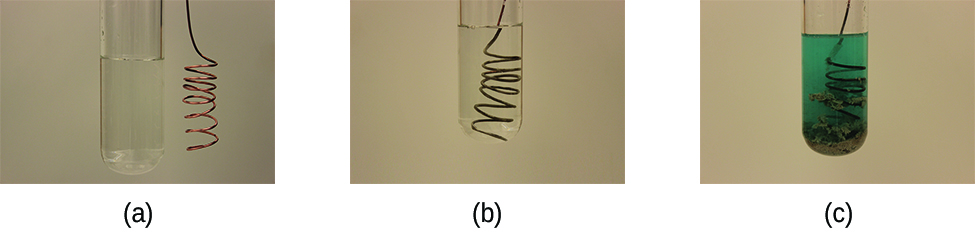
Before we look at how a galvanic cell works, let’s first see what happens when a clean piece of copper metal is placed in a solution of silver nitrate (Figure \(\PageIndex{1}\)). As soon as the copper metal is added, silver metal begins to form on the copper surface while copper ions pass into the solution. The blue colour of the solution (on the far right) indicates the presence of copper ions.
We can better understand what is happening by splitting the reaction into its two half-reactions:
\[\begin{align*}
&\textrm{oxidation: }\ce{Cu}(s)\rightarrow\ce{Cu^2+}(aq)+\ce{2e-}\\
&\underline{\textrm{reduction: }2×(\ce{Ag+}(aq)+\ce{e-}\rightarrow\ce{Ag}(s))\hspace{40px}\ce{or}\hspace{40px}\ce{2Ag+}(aq)+\ce{2e-}\rightarrow\ce{2Ag}(s)}\\
&\textrm{overall: }\ce{2Ag+}(aq)+\ce{Cu}(s)\rightarrow\ce{2Ag}(s)+\ce{Cu^2+}(aq)
\end{align*} \]
Notice that the reduction half-reaction is multiplied by two so that the number of electrons gained in the reduction equals the number of electrons lost in the oxidation.
Galvanic Cells
In the previous example, we saw that when a copper wire is placed directly into a silver nitrate solution, a redox reaction occurs spontaneously, with silver metal forming on the copper while copper ions enter the solution. However, in that setup, the energy from the electron transfer is released to the surroundings rather than being captured as usable electrical energy.
To harness that energy to do work, we can set up a galvanic (or voltaic) cell, which uses the same spontaneous redox reaction but separates the oxidation and reduction half-reactions into different containers (Figure \(\PageIndex{2}\)). This separation allows electrons to flow through an external wire, generating an electric current that can power a device or be measured.
In this setup, the left beaker is a half-cell containing a 1 M solution of copper(II) nitrate (\(\ce{Cu(NO3)2}\)) with a copper metal electrode. Here, copper undergoes oxidation and releases electrons, so the copper electrode is the anode.
The right beaker is another half-cell containing a 1 M solution of silver nitrate (\(\ce{AgNO3}\)) with a silver electrode. Here, silver ions in the solution gain electrons and are reduced to silver metal, making the silver electrode the cathode.
The reaction that occurs is the same as in the earlier example:
\[\begin{align*}
&\textrm{anode (oxidation): }\ce{Cu}(s)\rightarrow\ce{Cu^2+}(aq)+\ce{2e-}\\
&\underline{\textrm{cathode (reduction): }\ce{2Ag+}(aq)+\ce{2e-}\rightarrow\ce{2Ag}(s)}\\
&\textrm{overall: }\ce{2Ag+}(aq)+\ce{Cu}(s)\rightarrow\ce{2Ag}(s)+\ce{Cu^2+}(aq)
\end{align*} \]
Electrons released during oxidation at the anode give it a negative charge, while the cathode, which attracts these electrons, carries a positive charge. This charge difference creates a potential difference that drives electron flow through the external circuit.
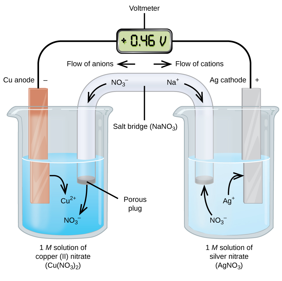
The two electrodes are connected by wires through a voltmeter to measure the voltage. However, until the salt bridge is in place, no current flows because the circuit is incomplete. To complete the circuit and allow ions to move between the half-cells to maintain electrical neutrality, we use a salt bridge containing a concentrated, nonreactive electrolyte solution (such as sodium nitrate, \(\ce{NaNO3}\)).
As the reaction proceeds:
- Electrons flow from the copper anode to the silver cathode through the wire.
- Nitrate ions (\(\ce{NO3^{−}}\)) move into the copper solution to balance the positive charge from the \(\ce{Cu^{2+}}\) formed during oxidation.
- Sodium ions (\(\ce{Na+}\)) move into the silver solution to replace the \(\ce{Ag+}\) ions being reduced and deposited as silver metal.
In addition to completing the circuit, the salt bridge prevents charge buildup, which would otherwise stop the flow of electrons.
When the circuit is completed, the voltmeter shows a positive voltage, known as the cell potential. This voltage is a measure of the electrical potential difference between the two electrodes and indicates how much energy per unit charge can be obtained from the redox reaction. For this copper–silver cell under standard conditions, the cell potential is +0.46 V, which confirms that the redox reaction is spontaneous and can produce electrical energy. The next section will explore how to calculate and interpret cell potentials.
Oxidation always occurs at the anode (AN OX – vowels go together!).
Reduction always occurs at the cathode (RED CAT – consonants go together!).
Electrons flow from the anode to the cathode in a galvanic cell.

A galvanic cell is constructed of a \(\ce{Zn}\)/\(\ce{Zn^{2+}}\) half cell and a \(\ce{Cu}\)/\(\ce{Cu^{2+}}\) half cell:

Electrons flow from the zinc electrode to the copper electrode.
a) Write the half-reactions for each half-cell.
b) Which electrode is the anode and which is the cathode?
c) Over time what will happen to the mass of the Zn electrode? The Cu electrode? Explain your reasoning.
d) Rationalize the flow of ions in the salt-bridge. Why is this necessary for the cell to continue operating?
Solution
a) Electrons flow from the zinc electrode to the copper electrode.
Oxidation is the process of losing electrons.
Since the zinc electrode is the source of the electrons flowing through the external circuit, it must be losing electrons.
Therefore, oxidation occurs at the zinc electrode:
\(\ce{Zn(s) \rightarrow Zn^{2+}(aq) + 2e-}\)
Conversely:
Reduction is the process of gaining electrons.
The copper electrode is receiving electrons coming through the wire from the zinc electrode.
Therefore, reduction occurs at the copper electrode:
\(\ce{Cu^{2+}(aq) + 2e- \rightarrow Cu(s)}\)
b)Anode: The Zn electrode is the anode because oxidation occurs here (loss of electrons).
Cathode: The Cu electrode is the cathode because reduction occurs here (gain of electrons).
c) Mass Changes Over Time:
At the Zn anode, zinc metal is oxidized to \(\ce{Zn^{2+}}\), which enters the solution, so the mass of the Zn electrode decreases over time.
At the Cu cathode, \(\ce{Cu^{2+}}\) ions in solution are reduced to solid \(\ce{Cu}\), which plates onto the electrode, so the mass of the Cu electrode increases over time.
- Click for image of electrodes
-

(CC BY-SA-NC; anonymous)
d)The salt bridge allows ions to move to maintain charge neutrality:
At the anode (Zn):
As \(\ce{Zn^{2+}}\)ions enter the solution, the solution becomes more positively charged.
Anions (\(\ce{Cl^{−}}\)) from the salt bridge move toward the anode to balance the charge.
At the cathode (Cu):
As \(\ce{Cu^{2+}}\)ions are removed from solution, the solution becomes more negatively charged.
Cations (\(\ce{Na+}\)) from the salt bridge move toward the cathode to balance the charge.
Without this ion flow, charge would build up in each half-cell, preventing further electron flow and stopping the cell from functioning.
A galvanic cell is constructed with a magnesium electrode in a \( \ce{Mg^{2+}} \) solution and a silver electrode in a \( \ce{Ag^{+}} \) solution. Electrons flow from the magnesium electrode to the silver electrode.
a) Write the half-reactions for the oxidation and reduction occurring in this cell.
b) What is the overall reaction occurring in the galvanic cell?
c) Identify which electrode is the anode and which is the cathode.
- Answer
-
a) Electrons flow from the magnesium electrode to the silver electrode, so:
Oxidation (at the anode):
\( \ce{Mg(s) \rightarrow Mg^{2+}(aq) + 2e^-} \)Reduction (at the cathode):
\( \ce{Ag^{+}(aq) + e^- \rightarrow Ag(s)} \)b) Since the oxidation half-reaction involves two electrons, we multiply the reduction half-reaction by 2 to balance electron transfer.
\( \ce{2Ag^{+}(aq) + 2e^- \rightarrow 2Ag(s)} \)
Overall reaction: \( \ce{2Ag^{+}(aq) + Mg(s) \rightarrow Mg^{2+}(aq) + 2Ag(s)} \)
c) The magnesium electrode is the anode because oxidation occurs there (loss of electrons). The silver electrode is the cathode because reduction occurs there (gain of electrons).
A common single use battery is the dry cell (Figure \(\PageIndex{3}\)), which uses a zinc can as both container and anode ( – terminal) and a graphite rod as the cathode (+ terminal). The Zn can is filled with an electrolyte paste containing manganese(IV) oxide, zinc(II) chloride, ammonium chloride, and water. As the battery operates:
At the anode, zinc is oxidized:
\(\ce{Zn(s) \rightarrow Zn^{2+}(aq) +2 e^{-}} \)
At the cathode, manganese(IV) oxide is reduced:
\(\ce{2 MnO2(s) + 2 NH4Cl(aq) + 2 e^{-} \rightarrow Mn2O3(s) + 2 NH3(aq) + H2O(l) + 2 Cl^{-}} \)
Giving the overall reaction:
\(\ce{2 MnO2(s) + 2NH4Cl(aq) + Zn(s) \rightarrow Zn^{2+}(aq) + Mn2O3(s) + 2 NH3(aq) + H2O(l) + 2 Cl^{-}} \)
Dry cells produce about 1.5 V. They come in various sizes (D, C, AA, AAA), but the voltage remains the same regardless of size. Larger cells simply contain more reactants, allowing them to power devices longer. Multiple dry cells can be connected in series in devices (like flashlights) to produce higher voltages.
Alkaline batteries (Figure \(\PageIndex{4}\)) were developed in the 1950s as improved dry cells. They use the same redox couples but replace the acidic paste with an alkaline potassium hydroxide electrolyte, which increases efficiency and extends the battery’s lifespan.
The cell reactions are:
anode: \(\ce{Zn(s) + 2OH^{-}(aq) \rightarrow ZnO(s) + H2O(l) + 2e^{-}}\)
cathode: \(\ce{2 MnO2(s) + H2O(l) + 2 e^{-} \rightarrow Mn2O3(s) + 2 OH^{-}(aq)}\)
overall: \(\ce{Zn(s) + 2 MnO2(s) \rightarrow ZnO(s) + Mn2O3(s)} \qquad E_{\text {cell }}=+1.43\,\text{V}\)
Alkaline batteries can deliver three to five times more energy than zinc-carbon dry cells of the same size, making them longer-lasting in devices like remotes, clocks, and flashlights. However, they can leak potassium hydroxide if left in devices for extended periods. Most alkaline batteries are not rechargeable, and attempting to recharge them can cause rupture and leakage.
Figure \(\PageIndex{4}\): Cross-section of an alkaline battery, which was developed as an improved replacement for zinc-carbon (dry cell) batteries, providing longer life and higher energy output.
Dry cells and alkaline batteries are practical examples of galvanic cells, converting chemical energy directly into electrical energy. They allow us to carry portable electricity in our backpacks, pockets, and devices, and understanding their chemistry connects the everyday act of replacing batteries to the redox reactions you learn in this course.
Shorthand Notation for Galvanic Cells
Describing galvanic cells in words or diagrams each time can be inconvenient, especially since there are many possible galvanic cells we might encounter in chemistry. To address this, chemists use a standardized shorthand notation (sometimes called a cell diagram) to represent galvanic cells clearly and efficiently. This notation concisely shows the species involved in the redox reaction, the direction of electron flow, and the operating conditions of the cell.
In this notation, the anode is written on the left, followed by the anode solution, the salt bridge (‖), the cathode solution, and finally the cathode on the right. Within each half-cell, species generally appear in the order they participate in the half-reaction (reactants then products), with electrodes placed on the outside.
- A vertical line, │, denotes a phase boundary (for example, between a solid electrode and an aqueous solution).
- A double vertical line, ‖, denotes the salt bridge (or porous barrier) separating the half-cells.
- Spectator ions are not included, and the simplest form of each half-reaction is used.
- Initial concentrations of the ions are often included when known.
Figure \(\PageIndex{5}\) shows the shorthand notation from the \(\ce{Zn}\)/\(\ce{Cu^{2+}}\) galvanic cell shown in

Figure \(\PageIndex{5}\): Shorthand notation for a \(\ce{Zn}\)/\(\ce{Cu^{2+}}\) galvanic cell. The anode species are on the left, the cathode species on the right, with the salt bridge (‖) in the middle. The concentrations of aqueous ions are included in parentheses (1 M under standard conditions).
Write the shorthand notation for the galvanic cell in Figure \(\PageIndex{2}\) and shown here:
- Answer
-
At the anode:
\(\textrm{anode (oxidation): }\ce{Cu}(s)\rightarrow\ce{Cu^2+}(aq)+\ce{2e-} \)
This is written as:
\(\ce{Cu}(s)│\ce{Cu^2+} \)
where│indicates the phase boundary between the copper electrode and \(\ce{Cu^{2+}}\) ions in solution.
At the cathode:
\({\textrm{cathode (reduction): }\ce{2Ag+}(aq)+\ce{2e-}\rightarrow\ce{2Ag}(s)}\)
This is written as:
\(\ce{Ag+}│\ce{Ag}(s)\)
Since the shorthand notation uses the simplest form of each half-reaction, we do not include the coefficient “2” in front of \(\ce{Ag+}\) and \(\ce{Ag}\).
The complete shorthand notation, with the salt bridge shown as ‖, is:
\[\ce{Cu}(s)│\ce{Cu^2+}(aq,\: 1\:M)║\ce{Ag+}(aq,\: 1\:M)│\ce{Ag}(s) \nonumber \]
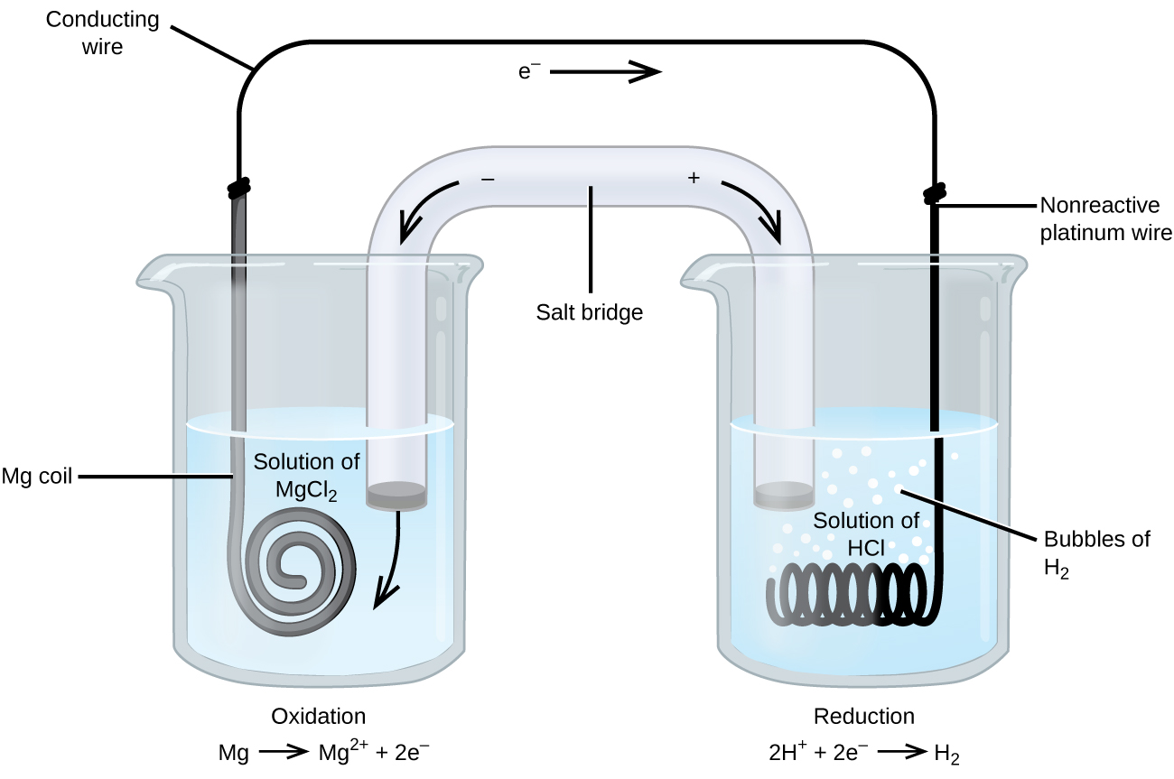
Some oxidation-reduction reactions involve species that are poor electrical conductors, requiring the use of an electrode that does not participate in the reaction. Frequently, the electrode is platinum, gold, or graphite, all of which are inert in most chemical reactions.
One such system is shown in Figure \(\PageIndex{6}\). Magnesium undergoes oxidation at the anode on the left, while hydrogen ions undergo reduction at the cathode on the right:
\[\begin{align*}
&\textrm{oxidation: }\ce{Mg}(s)\rightarrow\ce{Mg^2+}(aq)+\ce{2e-}\\
&\textrm{reduction: }\ce{2H+}(aq)+\ce{2e-}\rightarrow\ce{H2}(g)\\
&\overline{\textrm{overall: }\ce{Mg}(s)+\ce{2H+}(aq)\rightarrow\ce{Mg^2+}(aq)+\ce{H2}(g)}
\end{align*} \]
An inert platinum electrode is used as the cathode because the reduction half-reaction does not involve a solid product that can act as an electrode. In cell notation, the inert electrode is placed at the end of the cathode half-cell:
\[\ce{Mg(s)}│\ce{Mg^2+(aq)} ║ \ce{H+(aq)}│\ce{H2(g)}│\ce{Pt(s)} \nonumber \]
The magnesium electrode is an active electrode because it participates in the redox reaction, whereas the platinum electrode is inert; it does not participate in the reaction and serves only to conduct electrons and complete the circuit.
The following overall reaction occurs in a galvanic cell:
\[\ce{2Cr}(s)+\ce{3Cu^2+}(aq)\rightarrow\ce{2Cr^3+}(aq)+\ce{3Cu}(s) \nonumber \]
Write the oxidation and reduction half-reactions, identify which occurs at the anode and at the cathode, and write the cell notation.
Solution
The half-reactions are:
\[\begin{align*}\ce{2Cr(s)} & \rightarrow \ce{2Cr^{3+}(aq)} + \ce{6e-} \\ \ce{3Cu^2+(aq)} + \ce{6e-} & \rightarrow \ce{3Cu(s)}\end{align*}\] \[\overline{\ce{2Cr(s)} + \ce{3Cu^2+(aq)} \rightarrow \ce{2Cr^3+(aq)} + \ce{3Cu(s)}} \nonumber\]
\(\ce{Cr}\) loses electrons, so the first reaction is the oxidation half-reaction and occurs at the anode.
\(\ce{Cu^2+}\) gains electrons, so the bottom reaction is the reduction half-reaction and occurs at the cathode.
Cell notation uses the simplest form of each half-reaction and begins with the species at the anode. Since no concentrations are specified:
\[\ce{Cr(s)}│\ce{Cr^3+(aq)}║\ce{Cu^2+(aq)}│\ce{Cu(s)} \nonumber \]
The following overall reaction occurs in a galvanic cell with platinum electrodes:
\[\ce{5Fe^2+}(aq)+\ce{MnO4-}(aq)+\ce{8H+}(aq)\rightarrow\ce{5Fe^3+}(aq)+\ce{Mn^2+}(aq)+\ce{4H2O}(l) \nonumber \]
Write the oxidation and reduction half-reactions, identify which occurs at the anode and at the cathode, and write the cell notation.
- Answer
-
The half-reactions are:
\[
\begin{align*}
5\ce{Fe^{2+}(aq)} & \rightarrow 5\ce{Fe^{3+}(aq)} + 5\ce{e^-} \\
\ce{MnO4^{-}(aq)} + 8\ce{H^{+}(aq)} + 5\ce{e^-} & \rightarrow \ce{Mn^{2+}(aq)} + 4\ce{H2O(l)}
\end{align*} \]\[\overline{\ce{5Fe^{2+}(aq)} + \ce{MnO4^{-}(aq)} + 8\ce{H^{+}(aq)} \rightarrow \ce{5Fe^{3+}(aq)} + \ce{Mn^{2+}(aq)} + 4\ce{H2O(l)}}
\nonumber \]\(\ce{Fe^2+}\) loses electrons, so the first reaction is the oxidation half-reaction and occurs at the anode.
In the second half-reaction, electrons are gained, so it is the reduction half-reaction and occurs at the cathode.
Cell notation uses the simplest form of each half-reaction and begins with the species at the anode. Since no concentrations are specified:
\[\ce{Pt(s)}│\ce{Fe^2+(aq)},\: \ce{Fe^3+(aq)}║\ce{MnO4- (aq)},\: \ce{H+(aq)},\: \ce{Mn^2+(aq)}│\ce{Pt(s)} \nonumber \]
Summary
A galvanic cell (or voltaic cell) is an electrochemical cell that uses a spontaneous redox reaction to generate electrical energy. The cell separates the oxidation half-reaction from the reduction half-reaction, allowing the transfer of electrons to occur through an external wire so that the energy from the spontaneous reaction can do work.
Galvanic cells typically consist of two half-cells. One half-cell, usually shown on the left, contains the anode (negative), where oxidation occurs. The other half-cell, typically shown on the right, contains the cathode (positive), where reduction occurs.
A salt bridge is used to complete the circuit, allowing current to flow. Anions in the salt bridge flow toward the anode (to balance positive charge from oxidation), while cations flow toward the cathode (to replace the reduced ions). This movement maintains electrical neutrality in each half-cell and completes the circuit.
Galvanic cells can be described using cell notation. In this notation, information about the anode half-reaction appears on the left, and information about the cathode half-reaction appears on the right. The salt bridge is represented by a double vertical line, ‖, and different phases within a half-cell are separated by a single vertical line, │.
Active electrodes participate in the redox reaction. Inert electrodes do not participate in the redox reaction but provide a surface for electron transfer, allowing current to flow. Inert electrodes are often made from platinum or gold, which are stable in many chemical environments.