
11.8: Electrolysis
- Page ID
- 518136

\( \newcommand{\vecs}[1]{\overset { \scriptstyle \rightharpoonup} {\mathbf{#1}} } \)
\( \newcommand{\vecd}[1]{\overset{-\!-\!\rightharpoonup}{\vphantom{a}\smash {#1}}} \)
\( \newcommand{\dsum}{\displaystyle\sum\limits} \)
\( \newcommand{\dint}{\displaystyle\int\limits} \)
\( \newcommand{\dlim}{\displaystyle\lim\limits} \)
\( \newcommand{\id}{\mathrm{id}}\) \( \newcommand{\Span}{\mathrm{span}}\)
( \newcommand{\kernel}{\mathrm{null}\,}\) \( \newcommand{\range}{\mathrm{range}\,}\)
\( \newcommand{\RealPart}{\mathrm{Re}}\) \( \newcommand{\ImaginaryPart}{\mathrm{Im}}\)
\( \newcommand{\Argument}{\mathrm{Arg}}\) \( \newcommand{\norm}[1]{\| #1 \|}\)
\( \newcommand{\inner}[2]{\langle #1, #2 \rangle}\)
\( \newcommand{\Span}{\mathrm{span}}\)
\( \newcommand{\id}{\mathrm{id}}\)
\( \newcommand{\Span}{\mathrm{span}}\)
\( \newcommand{\kernel}{\mathrm{null}\,}\)
\( \newcommand{\range}{\mathrm{range}\,}\)
\( \newcommand{\RealPart}{\mathrm{Re}}\)
\( \newcommand{\ImaginaryPart}{\mathrm{Im}}\)
\( \newcommand{\Argument}{\mathrm{Arg}}\)
\( \newcommand{\norm}[1]{\| #1 \|}\)
\( \newcommand{\inner}[2]{\langle #1, #2 \rangle}\)
\( \newcommand{\Span}{\mathrm{span}}\) \( \newcommand{\AA}{\unicode[.8,0]{x212B}}\)
\( \newcommand{\vectorA}[1]{\vec{#1}} % arrow\)
\( \newcommand{\vectorAt}[1]{\vec{\text{#1}}} % arrow\)
\( \newcommand{\vectorB}[1]{\overset { \scriptstyle \rightharpoonup} {\mathbf{#1}} } \)
\( \newcommand{\vectorC}[1]{\textbf{#1}} \)
\( \newcommand{\vectorD}[1]{\overrightarrow{#1}} \)
\( \newcommand{\vectorDt}[1]{\overrightarrow{\text{#1}}} \)
\( \newcommand{\vectE}[1]{\overset{-\!-\!\rightharpoonup}{\vphantom{a}\smash{\mathbf {#1}}}} \)
\( \newcommand{\vecs}[1]{\overset { \scriptstyle \rightharpoonup} {\mathbf{#1}} } \)
\(\newcommand{\longvect}{\overrightarrow}\)
\( \newcommand{\vecd}[1]{\overset{-\!-\!\rightharpoonup}{\vphantom{a}\smash {#1}}} \)
\(\newcommand{\avec}{\mathbf a}\) \(\newcommand{\bvec}{\mathbf b}\) \(\newcommand{\cvec}{\mathbf c}\) \(\newcommand{\dvec}{\mathbf d}\) \(\newcommand{\dtil}{\widetilde{\mathbf d}}\) \(\newcommand{\evec}{\mathbf e}\) \(\newcommand{\fvec}{\mathbf f}\) \(\newcommand{\nvec}{\mathbf n}\) \(\newcommand{\pvec}{\mathbf p}\) \(\newcommand{\qvec}{\mathbf q}\) \(\newcommand{\svec}{\mathbf s}\) \(\newcommand{\tvec}{\mathbf t}\) \(\newcommand{\uvec}{\mathbf u}\) \(\newcommand{\vvec}{\mathbf v}\) \(\newcommand{\wvec}{\mathbf w}\) \(\newcommand{\xvec}{\mathbf x}\) \(\newcommand{\yvec}{\mathbf y}\) \(\newcommand{\zvec}{\mathbf z}\) \(\newcommand{\rvec}{\mathbf r}\) \(\newcommand{\mvec}{\mathbf m}\) \(\newcommand{\zerovec}{\mathbf 0}\) \(\newcommand{\onevec}{\mathbf 1}\) \(\newcommand{\real}{\mathbb R}\) \(\newcommand{\twovec}[2]{\left[\begin{array}{r}#1 \\ #2 \end{array}\right]}\) \(\newcommand{\ctwovec}[2]{\left[\begin{array}{c}#1 \\ #2 \end{array}\right]}\) \(\newcommand{\threevec}[3]{\left[\begin{array}{r}#1 \\ #2 \\ #3 \end{array}\right]}\) \(\newcommand{\cthreevec}[3]{\left[\begin{array}{c}#1 \\ #2 \\ #3 \end{array}\right]}\) \(\newcommand{\fourvec}[4]{\left[\begin{array}{r}#1 \\ #2 \\ #3 \\ #4 \end{array}\right]}\) \(\newcommand{\cfourvec}[4]{\left[\begin{array}{c}#1 \\ #2 \\ #3 \\ #4 \end{array}\right]}\) \(\newcommand{\fivevec}[5]{\left[\begin{array}{r}#1 \\ #2 \\ #3 \\ #4 \\ #5 \\ \end{array}\right]}\) \(\newcommand{\cfivevec}[5]{\left[\begin{array}{c}#1 \\ #2 \\ #3 \\ #4 \\ #5 \\ \end{array}\right]}\) \(\newcommand{\mattwo}[4]{\left[\begin{array}{rr}#1 \amp #2 \\ #3 \amp #4 \\ \end{array}\right]}\) \(\newcommand{\laspan}[1]{\text{Span}\{#1\}}\) \(\newcommand{\bcal}{\cal B}\) \(\newcommand{\ccal}{\cal C}\) \(\newcommand{\scal}{\cal S}\) \(\newcommand{\wcal}{\cal W}\) \(\newcommand{\ecal}{\cal E}\) \(\newcommand{\coords}[2]{\left\{#1\right\}_{#2}}\) \(\newcommand{\gray}[1]{\color{gray}{#1}}\) \(\newcommand{\lgray}[1]{\color{lightgray}{#1}}\) \(\newcommand{\rank}{\operatorname{rank}}\) \(\newcommand{\row}{\text{Row}}\) \(\newcommand{\col}{\text{Col}}\) \(\renewcommand{\row}{\text{Row}}\) \(\newcommand{\nul}{\text{Nul}}\) \(\newcommand{\var}{\text{Var}}\) \(\newcommand{\corr}{\text{corr}}\) \(\newcommand{\len}[1]{\left|#1\right|}\) \(\newcommand{\bbar}{\overline{\bvec}}\) \(\newcommand{\bhat}{\widehat{\bvec}}\) \(\newcommand{\bperp}{\bvec^\perp}\) \(\newcommand{\xhat}{\widehat{\xvec}}\) \(\newcommand{\vhat}{\widehat{\vvec}}\) \(\newcommand{\uhat}{\widehat{\uvec}}\) \(\newcommand{\what}{\widehat{\wvec}}\) \(\newcommand{\Sighat}{\widehat{\Sigma}}\) \(\newcommand{\lt}{<}\) \(\newcommand{\gt}{>}\) \(\newcommand{\amp}{&}\) \(\definecolor{fillinmathshade}{gray}{0.9}\)- Describe how electrolysis uses electricity to drive nonspontaneous redox reactions.
- Compare the operation of electrolytic and galvanic cells.
- Calculate the mass of substances deposited or consumed during electrolysis using current and time.
So far in this chapter, we have discussed galvanic cells, in which spontaneous redox reactions produce electrical energy. In these cells, a redox system does work on its surroundings as electrons produced by the redox reaction flow through an external circuit.
In this final section, we will examine the reverse scenario: using electrical energy to drive a nonspontaneous redox reaction. This process, called electrolysis, occurs when an external voltage is applied that is large enough to drive a nonspontaneous redox reaction.
Both galvanic and electrolytic cells contain two electrodes (solid metals) connected to an external circuit, providing a path for electron transfer (Figure \(\PageIndex{1}\)). Oxidation always occurs at the anode and reduction at the cathode, regardless of whether the cell is galvanic or electrolytic. When the circuit is closed, electrons always flow from the anode to the cathode. The electrodes are also connected by an electrolyte, an ionic substance or solution that allows ions to transfer between the electrode compartments, thereby maintaining the system’s electrical neutrality.
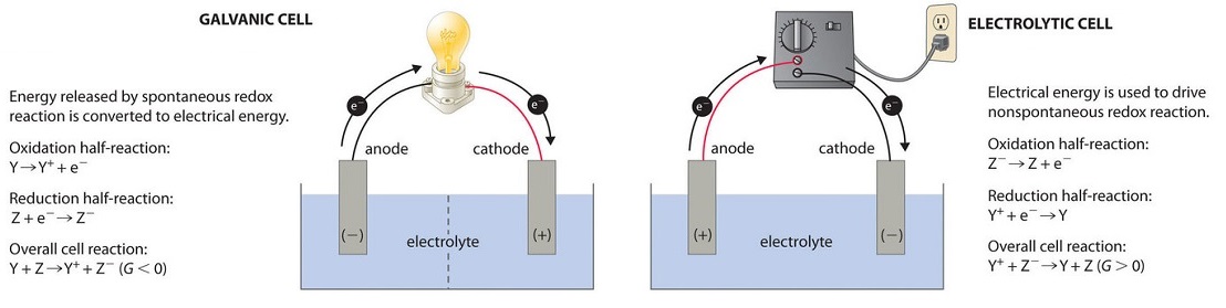
Figure \(\PageIndex{1}\): Electrochemical Cells. A galvanic cell (left) converts the energy from a spontaneous redox reaction into electrical energy. Oxidation and reduction usually occur in separate compartments, connected by an external electrical circuit and by a second connection that allows ions to flow between the compartments (shown here as a vertical dashed line to represent a porous barrier). The potential difference between the electrodes causes electrons to flow through the circuit, generating an electric current.
In an electrolytic cell (right), an external power source supplies electrical energy, generating a potential difference that forces electrons to flow and drives a nonspontaneous redox reaction. Most electrolytic cells use a single compartment.
A familiar example of electrolysis is recharging a battery, where an external power source forces the discharge reaction to run in reverse, partially restoring the cell composition and voltage. Electrolysis is also used in metal refining, the production of commodity chemicals, and electroplating (coating objects with a thin metal layer, as in jewelry, utensils, and automotive parts).
To illustrate the essential concepts of electrolysis, we will examine a few specific examples.
Electrolysis of Molten Sodium Chloride
Metallic sodium (\(\ce{Na}\)) and chlorine gas (\(\ce{Cl2}\)) are used in many applications, and their industrial production relies on the large-scale electrolysis of molten sodium chloride, \(\ce{NaCl(l)}\). This process typically uses a Downs cell, as shown in the simplified illustration in Figure \(\PageIndex{2}\). The reactions are:
\[
\begin{align*}
&\textrm{anode:} \quad && \ce{2Cl^{-}(l) \rightarrow Cl2(g) + 2e^{-}}
&& \quad E^\circ_{ox} = -1.36 \, \mathrm{V} \\[6pt]
&\textrm{cathode:} \quad && \ce{Na^{+}(l) + e^{-} \rightarrow Na(l)}
&& \quad E^\circ_{red} = -2.71 \, \mathrm{V} \\[6pt]
&\textrm{overall:} \quad && \overline{\ce{2Na^{+}(l) + 2Cl^{-}(l) \rightarrow 2Na(l) + Cl2(g)}}
&& \quad \overline{E^\circ_{cell} = -4.07 \, \mathrm{V}}
\end{align*}
\]
The cell potential for this process is negative, indicating that the reaction is not spontaneous under standard state conditions. The power supply (battery) must supply a minimum of 4.07 V, but, in practice, the applied voltages are typically higher because of inefficiencies in the process itself.
Electrolysis of Water
It is possible to split water into hydrogen and oxygen gas using electrolysis. To improve electrical conductivity without introducing a different redox species, a strong acid is typically added to increase the hydrogen ion concentration.
The redox processes associated with this cell are:
\[
\begin{align*}
&\text{oxidation: } \ce{2H2O(l) \rightarrow O2(g) + 4H+(aq) + 4e-} \ \ E^\circ_{ox} = -1.23 \,\text{V} \\[6pt]
&\text{reduction:} \ce{2H+(aq) + 2e- \rightarrow H2(g)} \quad \quad \quad \quad \ \ E^\circ_{red} = 0 \,\text{V} \\[6pt]
&\overline{\text{overall:} \quad \ce{2H2O(l) \rightarrow 2H2(g) + O2(g)} \quad \quad \quad E^\circ_{cell} = -1.23 \,\text{V}}
\end{align*}
\]
Again, the cell potential as written is negative, indicating a nonspontaneous cell reaction that must be driven by applying a voltage greater than +1.23 V. Keep in mind that these standard electrode potentials are used to inform thermodynamic predictions, but the cell is not operating under standard state conditions. Therefore, the calculated cell potential represents an approximate value rather than an exact voltage.
Electrolysis of Aqueous Sodium Chloride
The electrolysis of aqueous sodium chloride is more complicated than the electrolysis of molten salts because multiple species can be oxidized and reduced.
Anode reactions:
First, consider the anode. The possible oxidation reactions are:
\[\begin{align*}
&\textrm{(i) }\ce{2Cl-}(aq)\rightarrow\ce{Cl2}(g)+\ce{2e-} \hspace{20px} &E^\circ_\ce{ox}=\mathrm{-1.358\: V}\\
&\textrm{(ii) }\ce{2H2O}(l)\rightarrow\ce{O2}(g)+\ce{4H+}(aq)+\ce{4e-} \hspace{20px} &E^\circ_\ce{ox}=\mathrm{-1.229\: V}
\end{align*} \]
These standard potentials suggest that water should be oxidized at the anode because it requires a less negative potential (–1.229 V vs. –1.358 V for chloride ions). However, when the experiment is run, chlorine gas, not oxygen, is produced at the anode. This discrepancy is due to a concept called overpotential, which is the extra voltage beyond the theoretical potential that must be applied to make a reaction occur at a practical rate. Overpotential arises from kinetic barriers such as reaction mechanisms, electrode surface properties, and gas bubble formation, which can slow reactions even when thermodynamically favourable.
The detailed study of overpotential is beyond the scope of CHM 135H, but it is important to be aware that it can affect which reactions actually occur during electrolysis. In this case, the overpotential for producing oxygen gas is high enough that chloride ions are oxidized more easily under typical conditions. As a result, chlorine gas forms at the anode during the electrolysis of aqueous sodium chloride.
Cathode reactions:
Now consider the cathode. Three reductions could occur:
\[\begin{align*}
&\textrm{(iii) }\ce{2H+}(aq)+\ce{2e-}\rightarrow\ce{H2}(g) \hspace{20px} &E^\circ_\ce{red}=\mathrm{0.000\: V}\\
&\textrm{(iv) }\ce{2H2O}(l)+\ce{2e-}\rightarrow\ce{H2}(g)+\ce{2OH-}(aq) \hspace{20px} &E^\circ_\ce{red}=\mathrm{−0.828\:V}\\
&\textrm{(v) }\ce{Na+}(aq)+\ce{e-}\rightarrow\ce{Na}(s) \hspace{20px} &E^\circ_\ce{red}=\mathrm{−2.71\: V}
\end{align*} \]
Reduction of sodium ions (v) is ruled out because it requires a highly negative potential. Under standard conditions, the reduction of hydrogen ions (iii) would be favoured over water reduction (iv). However, in a neutral sodium chloride solution (pH 7), the hydrogen ion concentration is only 1 × 10⁻⁷ M, making reaction (iii) infrequent. Thus, water is reduced at the cathode, producing hydrogen gas and hydroxide ions (reaction iv).
Overall cell reaction:
\[\textrm{overall: }\ce{2H2O}(l)+\ce{2Cl-}(aq)\rightarrow\ce{H2}(g)+\ce{Cl2}(g)+\ce{2OH-}(aq) \hspace{20px} E^\circ_\ce{cell}=\mathrm{−2.186\: V} \nonumber \]
As electrolysis proceeds, hydroxide ions replace chloride ions in solution. By evaporating the water after electrolysis, sodium hydroxide can be collected. Sodium hydroxide is a valuable industrial product used in oven cleaners, drain openers, and in the production of paper, fabrics, and soap.
Electroplating
An important use of electrolytic cells is electroplating, which deposits a thin coating of one metal onto a conducting surface. Electroplating can make an object more corrosion-resistant, strengthen its surface, improve its appearance, or purify a metal. Common electroplating metals include cadmium, chromium, copper, gold, nickel, silver, and tin. Consumer products that often use electroplating include silver- or gold-plated tableware, chrome-plated automobile parts, and jewelry. We can see how electroplating works by looking at the production of silver-plated tableware (Figure \(\PageIndex{4}\)).
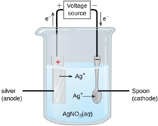
In the figure, the anode (left) is a silver electrode, and the cathode (right) is the spoon. Both electrodes are immersed in a silver nitrate (\(\ce{AgNO3}\)) solution. When the potential is applied and current flows, silver metal is oxidized at the anode:
anode: \(\ce{Ag(s) \rightarrow Ag+ (aq) + e- }\)
At the cathode, silver ions from the solution gain electrons and are deposited onto the spoon:
cathode: \(\ce{Ag+ (aq) + e- \rightarrow Ag(s)}\)
The net result is the transfer of silver metal from the anode to the cathode, building up a thin, even layer of silver on the surface of the spoon. The quality of electroplating is determined by the thickness and uniformity of the deposited layer, which depend on the current and the time the object is plated.
Lithium ion batteries (Figure \(\PageIndex{5}\)) power many of the devices we use every day, from phones to laptops and electric vehicles. These batteries are popular because they are lightweight, deliver high current, provide a nearly constant voltage during discharge, and retain their charge well during storage.
During discharge, lithium ions move from the graphite anode (negative electrode) to the metal oxide cathode (positive electrode), providing electrical energy. When the battery is charged, an external power source forces the lithium ions back into the graphite anode, storing energy for later use.
The cell reactions during discharge are:
\[\begin{align*}
& \text { anode: } \quad && \ce{ Li_{x}C6 \rightarrow x~ Li^{+} + x~e^{-} + C6(s)} \\[4pt]
& \text {cathode: } \quad && \ce{Li_{1-x}CoO2(s) + x~ Li^{+} + x~ e^{-} \rightarrow LiCoO2} \\[4pt]
\hline &\text { cell: } \quad && \ce{Li_{1-x}CoO2(s) + Li_{x}C6 \rightarrow LiCoO2 + C6(s)} \quad \quad \quad E_{\text {cell }}\approx+3.7\,\text{V}
\end{align*} \nonumber \]
In this notation, x represents the fraction of lithium ions that move during charging and discharging. The ability of lithium ions to move reversibly between the two electrodes allows lithium-ion batteries to store and deliver energy efficiently.
Lead-acid batteries (Figure \(\PageIndex{6}\)) are among the oldest rechargeable batteries and are widely used in cars to power starter motors, lights, and electronics. They are valued for their ability to deliver a high current quickly and their low cost, despite being heavy and containing a corrosive sulfuric acid electrolyte. Each lead-acid cell provides about 2 V, and six cells are connected in series to form a 12-V car battery. The reactions in a lead-acid battery are:
\[\begin{align*}
& \text { anode: } \quad && \ce{Pb(s) + HSO4^{-}(aq) \rightarrow PbSO4(s) + H^{+}(aq) + 2 e^{-}} \\[4pt]
& \text {cathode: } \quad && \ce{PbO2(s) + HSO4^{-}(aq) + 3 H^{+}(aq) + 2 e^{-} \rightarrow PbSO4(s) + 2 H2O(l)} \\[4pt]
\hline &\text { cell: } \quad && \ce{Pb(s) + PbO2(s) + 2 H2SO4(aq) \rightarrow 2 PbSO4(s) + 2 H2O (l)} \quad \quad \quad E_{\text {cell }}\approx +2\,\text{V}
\end{align*} \nonumber \]
While lead-acid batteries are reliable and easily rechargeable, they contain a significant amount of lead and must be disposed of properly to prevent environmental contamination.
These examples illustrate how electrolysis and redox chemistry power the batteries in our everyday lives, providing the energy to start cars, run devices, and store renewable energy.
Quantitative Aspects of Electrolysis
Electrical current is defined as the rate of flow of charge. In the context of electrolysis, this usually refers to the flow of electrons through an external circuit. Current is measured in amperes (A), where:
\[1 A=1 C/s\nonumber\]
meaning that one ampere corresponds to one coulomb of charge passing a point per second.
The total charge transferred, \(Q\), when a constant current, \(I\), flows for a time interval, \(t\), is given by:
\[Q = I t\nonumber\]
When electrons are transferred during a redox process, the stoichiometry of the reaction can be used to determine the total charge involved. For example, in the generic reduction process:
\[\ce{M^{n+} (aq) + n e- \rightarrow M(s)} \nonumber\]
\(n\) electrons are transferred for each \(\ce{M^{n+}}\) reduced. The total charge transferred is therefore:
\[Q = moles(e^{-}) \times F\nonumber\]
where \(F\) is Faraday’s constant, the charge carried by one mole of electrons (\(F\) = 96,485 C/mol).
When electrolysis occurs in an electrochemical cell, current can be measured directly and used in stoichiometric calculations related to the cell’s redox reaction. By combining \(Q = It\) and \(Q = moles(e^{-}) \times F\), you can determine the amount of substance produced or consumed during electrolysis based on the current and time the current is applied.
In one process used for electroplating silver, a current of 10.23 A was passed through an electrolytic cell for 1 hour (3600 s). How many moles of electrons passed through the cell? What mass of silver was deposited at the cathode from the silver nitrate solution?
Solution
Calculate the total charge transferred:
\[Q = I t = (10.23 \frac{C}{s})(3600 \ s) = 3.683 \times 10^4 \ C\nonumber\]
Calculate moles of electrons using Faraday’s constant:
\[Q = moles(e^{-}) \times F \ \Rightarrow \ moles(e^{-}) = \frac{Q}{F}=\frac{3.683 \times 10^4 \, \text{C}}{96485\, \text{C/mol}} = 0.3817 \, \text{mol} \nonumber\]
Determine mass of silver deposited:
From cathode half-reaction:
\[\ce{Ag^{+}(aq) + e^{-} \rightarrow Ag(s)} \nonumber\]
1 mol of electrons deposits 1 mol of Ag.
Using the molar mass of silver (107.9 g/mol):
\[\text{mass}\, Ag =0.3817\,\text{mol e}^{-} \times \dfrac{1\, \text{mol}\,\ce{Ag}}{1\,\text{mol}\,\ce{e}^{-}} \times \frac{107.9\,\text{g}\,\ce{Ag}}{1\,\text{mol}\,\ce{Ag}}=41.19\,\text{g}\,\ce{Ag} \nonumber \]
Aluminum metal can be made from aluminum(III) ions by electrolysis. What is the half-reaction at the cathode? What mass of aluminum metal would be recovered if a current of 25.0 A passed through the solution for 15.0 minutes?
- Answer
-
\[Al^{3+}(aq) +3 e^{-} \rightarrow Al (s) \nonumber \]
\[(25.0\ \text{C/s})(15.0 \ \text{min })\left(\frac{60 \ \text{s}}{\text{min}}\right) \left( \frac{mol \ e^-}{96485 \ \text{C}}\right) \left( \frac{1 \ mol \ Al}{3 \ mol \ e^-} \right)\left(\frac{26.98 \ \text{g}}{mol} \right)=2.10 \ \text{g Al} \nonumber\]
Summary
An electrolytic cell uses electrical energy to drive a nonspontaneous redox reaction. Oxidation occurs at the anode and reduction at the cathode.
When more than one product is possible at an electrode, the substance that is more easily oxidized forms at the anode, while the substance that is more easily reduced forms at the cathode. However, in some cases, the predicted product does not form due to overpotential (overvoltage), which is the additional voltage required to drive a reaction at a practical rate.
Electroplating uses electrolysis to deposit a thin layer of metal onto a conducting surface, improving corrosion resistance, appearance, or strength.
The quantitative aspects of electrolysis can be summarized using the relationships:
\(Q=I×t\) and \(Q=moles(e^{-})\times F \)
where:
Q = total charge transferred (C),
I = current (A),
t = time (s),
moles (e-) = actual amount of moles of electrons transferred,
F = Faraday’s constant (96,485 C/mol).
These relationships allow the calculation of the mass of a substance produced or consumed during electrolysis based on the measured current and the time the current is applied.
In all electrolytic cells, the key distinction from galvanic cells is that an external power source must supply energy to drive the redox reaction, as it is not thermodynamically spontaneous.