
Spectrometer
- Page ID
- 335
\( \newcommand{\vecs}[1]{\overset { \scriptstyle \rightharpoonup} {\mathbf{#1}} } \)
\( \newcommand{\vecd}[1]{\overset{-\!-\!\rightharpoonup}{\vphantom{a}\smash {#1}}} \)
\( \newcommand{\dsum}{\displaystyle\sum\limits} \)
\( \newcommand{\dint}{\displaystyle\int\limits} \)
\( \newcommand{\dlim}{\displaystyle\lim\limits} \)
\( \newcommand{\id}{\mathrm{id}}\) \( \newcommand{\Span}{\mathrm{span}}\)
( \newcommand{\kernel}{\mathrm{null}\,}\) \( \newcommand{\range}{\mathrm{range}\,}\)
\( \newcommand{\RealPart}{\mathrm{Re}}\) \( \newcommand{\ImaginaryPart}{\mathrm{Im}}\)
\( \newcommand{\Argument}{\mathrm{Arg}}\) \( \newcommand{\norm}[1]{\| #1 \|}\)
\( \newcommand{\inner}[2]{\langle #1, #2 \rangle}\)
\( \newcommand{\Span}{\mathrm{span}}\)
\( \newcommand{\id}{\mathrm{id}}\)
\( \newcommand{\Span}{\mathrm{span}}\)
\( \newcommand{\kernel}{\mathrm{null}\,}\)
\( \newcommand{\range}{\mathrm{range}\,}\)
\( \newcommand{\RealPart}{\mathrm{Re}}\)
\( \newcommand{\ImaginaryPart}{\mathrm{Im}}\)
\( \newcommand{\Argument}{\mathrm{Arg}}\)
\( \newcommand{\norm}[1]{\| #1 \|}\)
\( \newcommand{\inner}[2]{\langle #1, #2 \rangle}\)
\( \newcommand{\Span}{\mathrm{span}}\) \( \newcommand{\AA}{\unicode[.8,0]{x212B}}\)
\( \newcommand{\vectorA}[1]{\vec{#1}} % arrow\)
\( \newcommand{\vectorAt}[1]{\vec{\text{#1}}} % arrow\)
\( \newcommand{\vectorB}[1]{\overset { \scriptstyle \rightharpoonup} {\mathbf{#1}} } \)
\( \newcommand{\vectorC}[1]{\textbf{#1}} \)
\( \newcommand{\vectorD}[1]{\overrightarrow{#1}} \)
\( \newcommand{\vectorDt}[1]{\overrightarrow{\text{#1}}} \)
\( \newcommand{\vectE}[1]{\overset{-\!-\!\rightharpoonup}{\vphantom{a}\smash{\mathbf {#1}}}} \)
\( \newcommand{\vecs}[1]{\overset { \scriptstyle \rightharpoonup} {\mathbf{#1}} } \)
\(\newcommand{\longvect}{\overrightarrow}\)
\( \newcommand{\vecd}[1]{\overset{-\!-\!\rightharpoonup}{\vphantom{a}\smash {#1}}} \)
\(\newcommand{\avec}{\mathbf a}\) \(\newcommand{\bvec}{\mathbf b}\) \(\newcommand{\cvec}{\mathbf c}\) \(\newcommand{\dvec}{\mathbf d}\) \(\newcommand{\dtil}{\widetilde{\mathbf d}}\) \(\newcommand{\evec}{\mathbf e}\) \(\newcommand{\fvec}{\mathbf f}\) \(\newcommand{\nvec}{\mathbf n}\) \(\newcommand{\pvec}{\mathbf p}\) \(\newcommand{\qvec}{\mathbf q}\) \(\newcommand{\svec}{\mathbf s}\) \(\newcommand{\tvec}{\mathbf t}\) \(\newcommand{\uvec}{\mathbf u}\) \(\newcommand{\vvec}{\mathbf v}\) \(\newcommand{\wvec}{\mathbf w}\) \(\newcommand{\xvec}{\mathbf x}\) \(\newcommand{\yvec}{\mathbf y}\) \(\newcommand{\zvec}{\mathbf z}\) \(\newcommand{\rvec}{\mathbf r}\) \(\newcommand{\mvec}{\mathbf m}\) \(\newcommand{\zerovec}{\mathbf 0}\) \(\newcommand{\onevec}{\mathbf 1}\) \(\newcommand{\real}{\mathbb R}\) \(\newcommand{\twovec}[2]{\left[\begin{array}{r}#1 \\ #2 \end{array}\right]}\) \(\newcommand{\ctwovec}[2]{\left[\begin{array}{c}#1 \\ #2 \end{array}\right]}\) \(\newcommand{\threevec}[3]{\left[\begin{array}{r}#1 \\ #2 \\ #3 \end{array}\right]}\) \(\newcommand{\cthreevec}[3]{\left[\begin{array}{c}#1 \\ #2 \\ #3 \end{array}\right]}\) \(\newcommand{\fourvec}[4]{\left[\begin{array}{r}#1 \\ #2 \\ #3 \\ #4 \end{array}\right]}\) \(\newcommand{\cfourvec}[4]{\left[\begin{array}{c}#1 \\ #2 \\ #3 \\ #4 \end{array}\right]}\) \(\newcommand{\fivevec}[5]{\left[\begin{array}{r}#1 \\ #2 \\ #3 \\ #4 \\ #5 \\ \end{array}\right]}\) \(\newcommand{\cfivevec}[5]{\left[\begin{array}{c}#1 \\ #2 \\ #3 \\ #4 \\ #5 \\ \end{array}\right]}\) \(\newcommand{\mattwo}[4]{\left[\begin{array}{rr}#1 \amp #2 \\ #3 \amp #4 \\ \end{array}\right]}\) \(\newcommand{\laspan}[1]{\text{Span}\{#1\}}\) \(\newcommand{\bcal}{\cal B}\) \(\newcommand{\ccal}{\cal C}\) \(\newcommand{\scal}{\cal S}\) \(\newcommand{\wcal}{\cal W}\) \(\newcommand{\ecal}{\cal E}\) \(\newcommand{\coords}[2]{\left\{#1\right\}_{#2}}\) \(\newcommand{\gray}[1]{\color{gray}{#1}}\) \(\newcommand{\lgray}[1]{\color{lightgray}{#1}}\) \(\newcommand{\rank}{\operatorname{rank}}\) \(\newcommand{\row}{\text{Row}}\) \(\newcommand{\col}{\text{Col}}\) \(\renewcommand{\row}{\text{Row}}\) \(\newcommand{\nul}{\text{Nul}}\) \(\newcommand{\var}{\text{Var}}\) \(\newcommand{\corr}{\text{corr}}\) \(\newcommand{\len}[1]{\left|#1\right|}\) \(\newcommand{\bbar}{\overline{\bvec}}\) \(\newcommand{\bhat}{\widehat{\bvec}}\) \(\newcommand{\bperp}{\bvec^\perp}\) \(\newcommand{\xhat}{\widehat{\xvec}}\) \(\newcommand{\vhat}{\widehat{\vvec}}\) \(\newcommand{\uhat}{\widehat{\uvec}}\) \(\newcommand{\what}{\widehat{\wvec}}\) \(\newcommand{\Sighat}{\widehat{\Sigma}}\) \(\newcommand{\lt}{<}\) \(\newcommand{\gt}{>}\) \(\newcommand{\amp}{&}\) \(\definecolor{fillinmathshade}{gray}{0.9}\)Strictly speaking, a spectrometer is any instrument used to view and analyze a range (or a spectrum) of a given characteristic for a substance (for example, a range of mass-to-charge values as in mass spectrometry), or a range of wavelengths as in absorption spectrometry like nuclear magnetic radiation spectroscopy or infrared spectroscopy). A spectrophotometer is a spectrometer that only measures the intensity of electromagnetic radiation (light) and is distinct from other spectrometers such as mass spectrometers.
A spectrometer is typically used to measure wavelengths of electromagnetic radiation (light) that has interacted with a sample. Incident light can be reflected off, absorbed by, or transmitted through a sample; the way the incident light changes during the interaction with the sample is characteristic of the sample. A spectrometer measures this change over a range of incident wavelengths (or at a specific wavelength).
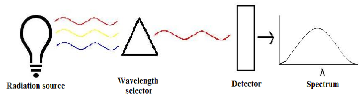
There are three main components in all spectrometers; these components can vary widely between instruments for specific applications and levels of resolution. Very generally, these components produce the electromagnetic radiation, somehow narrows the electromagnetic radiation to a specified range, and then detect the resulting electromagnetic radiation after is has interacted with the sample.
Sources of Radiation
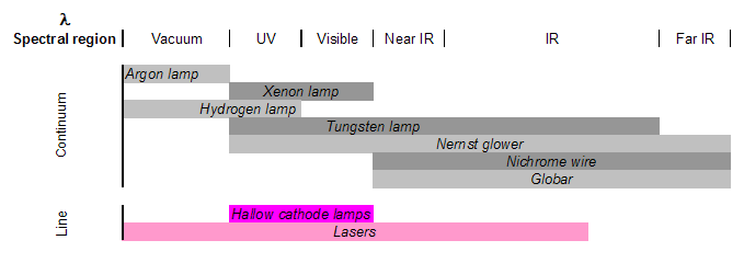
There are two classes of radiation sources used in spectrometry: continuum sources and line sources. The former are usually lamps or heated solid materials that emit a wide range of wavelengths that must be narrowed greatly using a wavelength selection element to isolate the wavelength of interest. The latter sources include lasers and specialized lamps, that are designed to emit discrete wavelengths specific to the lamp’s material.
Electrode lamps are constructed of a sealed, gas-filled chamber that has one or more electrodes inside. Electrical current is passed through the electrode, which causes excitation of the gas. This excitation produces radiation at a wavelength or a range of wavelengths, specific to the gas. Examples include argon, xenon, hydrogen or deuterium, and tungsten lamps, which emit radiation in the following ranges.
There are also non-electrode lamps used as line sources that contain a gas and a piece of metal that will emit narrow radiation at the desired wavelength. Ionization of the gas occurs from radiation (usually in the radio or microwave frequencies). The metal atoms are then excited by a transfer of energy from the gas, thereby producing radiation at a very specific wavelength.
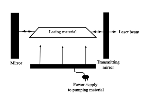
Laser (an acronym for light amplification by stimulated emission of radiation) sources work by externally activating a lasing material so that photons of a specific energy are produced and aimed at the material. This triggers photon production within the material, with more and more photons being produced as they reflect inside the material. Because all the photons are of equal energy they are all in phase with each other so that energy (and wavelength) is isolated and enhanced. The photons are eventually focused into a narrow beam and then directed at the sample.
Wavelength Selection
There are three methods of narrowing the incident electromagnetic radiation down to the desired wavelength: dispersive or non-dispersive.
Non-dispersive Elements
Wavelength selection elements are non-dispersive materials that filter out the unwanted ranges of wavelengths from the incident light source, thereby allowing only a certain range of wavelengths to pass through. For example, UV filters (as used on cameras) work by absorbing the UV radiation (100-400nm) but allowing other wavelengths to be transmitted. This type of filter is not common in modern spectrometers now that there are more precise elements available for narrowing the radiation.
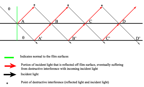
There are also interference filters that select wavelengths by causing interference effects between the incident and reflected radiation waves at each of the material boundaries in the filter. The filter has layers of a dielectric material, semitransparent metallic films, and glass; the incident light is partitioned according to the properties of each material as it passes through the layers (Ingle). If the light is of the proper wavelength when it encounters the second metallic film, then the reflected portion remains in phase with some of the incident light still entering that layer. This effectively isolates and enhances this particular wavelength while all others are removed via destructive interference.

One filter can be adjusted to allow various wavelengths to pass through it by manually changing the angle of the incident radiation (\(\theta\)) angle:
\[2d \sqrt{\epsilon^2 – \sin^2 } = m \lambda \nonumber \]
Where \(d\) is the thickness of the dialectic material (on the order of the wavelength of interest), ? is the refractive index of the material, \(m\) is the order of interference, and ? is the passable wavelength. This shows that for a given material (constant d, \(\epsilon\), and m) changing \(\lambda\) results in a different \(\theta\). Note that when the incident radiation is normal (perpendicular) to the filter surface, then the transmittable wavelength is independent of the radiation angle:
\[ \theta = \dfrac{2d\lambda}{m} \nonumber \]
Interferometers are also non-dispersive systems that use reflectors (usually mirrors) to direct the incident radiation along a specified path before being recombined and/or focused. Some systems also include a beam splitter that divides the incident beam and directs each portion along a different path before being recombined and directed to the detector. When the beams are recombined, only the radiation that is in phase when the beams recombine will be detected. All other radiation suffers destructive interference and is therefore removed from the spectrum. An interferogram is a photographic record produced by an interferometer.
A Fabry-Perot Interferometer allows the incident radiation to be reflected back and forth between a pair of reflective plates that are separated by an air gap (Ingle). Diffuse, multi-beam incident radiation passes through a lens and is directed to the plates. Some of the radiation reflects out of the plates back towards the incident source. The remaining radiation reflects back and forth between the plates and is eventually transmitted through the pair of plates towards a focusing lens. Here all constructively interfering radiation is focused onto a screen where it creates a dark or bright spot.
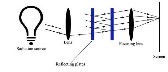
Constructive interference occurs when
\[2d \cos \theta’ = m? \nonumber \]
Where \(\theta’\) equals the angle of refraction in the air gap. This air gap can be changed to isolate particular wavelengths.
The mathematics relationships of the Fabry-Perot Interferometer relates the difference in the optical path length, \(\Delta(OPL)\), with the reflectance of the plate coatings:
\[\Delta(OPL) = 2d\lambda \cos \theta’ \nonumber \]
Phase difference = ? = 2? (2d? cos ?’)/ ?
And ? ? 4?/(1- ?)2
Where ? is the reflectance of the plate coating.
A Michelson Interferometer uses a beam splitter plate to divide the incident radiation into two beams of equal intensity. A pair of perpendicular mirrors then reflects the beams back to the splitter plate where they recombine and are directed towards the detector. One mirror is movable and the other is stationary. By moving one mirror, the path length of each beam is different, creating interference at the detector that can be measured as a function of the position of the movable mirror. At a certain distance from the splitter plate, the movable mirror causes constructive interference of the radiation at the detector such that a bright spot is detected. By varying the distance from this location, the adjustable mirror causes the radiation to fluctuate sinusoidally between being “in phase” or “out of phase” at the detector (Ingle).
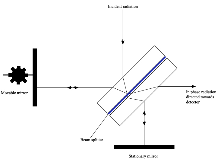
The sample material to be tested is placed in the path of one of the interferometer’s beams, which changes the path length difference between the two beams. It is the change in the interference pattern at the detector between the two beams that is measured.
Other interferometers work in a similar manner, but change the angle of the mirrors rather than the position. These variations are found in the Sagnac Interferometer or the Mach-Zender Interferometer.
Dispersive Elements
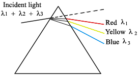
These work by dispersing the incident radiation out spatially, creating a spectrum of wavelengths (Ingle). In a prism the diffuse radiation beam is separated because of the refractive index of the material. For example, when white light is shone onto a prism, a rainbow of colors is observed coming out the other side. This is a result of wavelength dependence on the refractive index of the prism material.
Gratings are also used to disperse incident light into component wavelengths. They work by reflecting the light off the angled grating surface, causing the wavelengths to be dispersed through constructive interference at wavelength-dependent diffraction angles (Ingle).
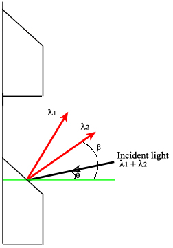
The condition for constructive interference (and therefore wavelength selection) on a grating surface is:
\[d (\sin \theta + \sin \theta) = m \theta \nonumber \]
This relationship shows that the wavelength selection is not based on the grating material, but on the angle of incidence (\(\theta\)). The angle \(\theta\) can also be used to describe the angle between normal and ?1.
Detector
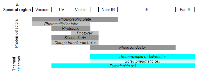
Detectors are transducers that transform the analog output of the spectrometer into an electrical signal that can be viewed and analyzed using a computer. There are two types: photon detectors and thermal detectors.
- Photon detectors work generally by either causing electrons to be emitted or development of current when photons strike the detector surface. Examples include photovoltaic cells, phototubes, and charge-transfer transducers. Photovoltaic cells generate electrical current on a semiconductor material when photons in the visible region are absorbed. Phototubes, however, emit electrons from a photon-sensitive material. Charge-transfer transducers (such as photodiodes) develop a charge from visible region photon-induced electron transfer reactions within a silicon material. In each case, it is the current, the number of electrons, or the charge that is actually detected (not the photons themselves) and is then related to the energy/quantity of photons that caused the change in the material.
- Thermal detectors detect a temperature change in a material due to photon absorption. Thermocouples work by measuring the difference in temperature between a pair of junctions (usually the reference against the sample) and are generally used for the infrared wavelengths. The temperature difference is related to a potential difference, which is the output signal. Pyroelectric transducers are used in infrared region and utilize a dielectric material that produces a current when its temperature is changed by radiation absorption.
References
- Atkins, P and de Paula, J. Physical Chemistry for the Life Sciences. Oxford University Press. New York, 2006. Chapter 13.
- Ingle, JD. Spectrochemical Analysis. Prentice Hall. London, 1988. Chapter 3.
- Pavia, DL. Introduction to Spectroscopy , Third Edition. Thomas Learning, Inc. Singapore, 2001. Page 390.
- Skoog, DA. Principles of Instrumental Analysis, Fifth Edition. Harcourt Brace. Philadelphia, 1998. Chapter 7.