FTIR: Computational
- Page ID
- 343
\( \newcommand{\vecs}[1]{\overset { \scriptstyle \rightharpoonup} {\mathbf{#1}} } \)
\( \newcommand{\vecd}[1]{\overset{-\!-\!\rightharpoonup}{\vphantom{a}\smash {#1}}} \)
\( \newcommand{\id}{\mathrm{id}}\) \( \newcommand{\Span}{\mathrm{span}}\)
( \newcommand{\kernel}{\mathrm{null}\,}\) \( \newcommand{\range}{\mathrm{range}\,}\)
\( \newcommand{\RealPart}{\mathrm{Re}}\) \( \newcommand{\ImaginaryPart}{\mathrm{Im}}\)
\( \newcommand{\Argument}{\mathrm{Arg}}\) \( \newcommand{\norm}[1]{\| #1 \|}\)
\( \newcommand{\inner}[2]{\langle #1, #2 \rangle}\)
\( \newcommand{\Span}{\mathrm{span}}\)
\( \newcommand{\id}{\mathrm{id}}\)
\( \newcommand{\Span}{\mathrm{span}}\)
\( \newcommand{\kernel}{\mathrm{null}\,}\)
\( \newcommand{\range}{\mathrm{range}\,}\)
\( \newcommand{\RealPart}{\mathrm{Re}}\)
\( \newcommand{\ImaginaryPart}{\mathrm{Im}}\)
\( \newcommand{\Argument}{\mathrm{Arg}}\)
\( \newcommand{\norm}[1]{\| #1 \|}\)
\( \newcommand{\inner}[2]{\langle #1, #2 \rangle}\)
\( \newcommand{\Span}{\mathrm{span}}\) \( \newcommand{\AA}{\unicode[.8,0]{x212B}}\)
\( \newcommand{\vectorA}[1]{\vec{#1}} % arrow\)
\( \newcommand{\vectorAt}[1]{\vec{\text{#1}}} % arrow\)
\( \newcommand{\vectorB}[1]{\overset { \scriptstyle \rightharpoonup} {\mathbf{#1}} } \)
\( \newcommand{\vectorC}[1]{\textbf{#1}} \)
\( \newcommand{\vectorD}[1]{\overrightarrow{#1}} \)
\( \newcommand{\vectorDt}[1]{\overrightarrow{\text{#1}}} \)
\( \newcommand{\vectE}[1]{\overset{-\!-\!\rightharpoonup}{\vphantom{a}\smash{\mathbf {#1}}}} \)
\( \newcommand{\vecs}[1]{\overset { \scriptstyle \rightharpoonup} {\mathbf{#1}} } \)
\( \newcommand{\vecd}[1]{\overset{-\!-\!\rightharpoonup}{\vphantom{a}\smash {#1}}} \)
\(\newcommand{\avec}{\mathbf a}\) \(\newcommand{\bvec}{\mathbf b}\) \(\newcommand{\cvec}{\mathbf c}\) \(\newcommand{\dvec}{\mathbf d}\) \(\newcommand{\dtil}{\widetilde{\mathbf d}}\) \(\newcommand{\evec}{\mathbf e}\) \(\newcommand{\fvec}{\mathbf f}\) \(\newcommand{\nvec}{\mathbf n}\) \(\newcommand{\pvec}{\mathbf p}\) \(\newcommand{\qvec}{\mathbf q}\) \(\newcommand{\svec}{\mathbf s}\) \(\newcommand{\tvec}{\mathbf t}\) \(\newcommand{\uvec}{\mathbf u}\) \(\newcommand{\vvec}{\mathbf v}\) \(\newcommand{\wvec}{\mathbf w}\) \(\newcommand{\xvec}{\mathbf x}\) \(\newcommand{\yvec}{\mathbf y}\) \(\newcommand{\zvec}{\mathbf z}\) \(\newcommand{\rvec}{\mathbf r}\) \(\newcommand{\mvec}{\mathbf m}\) \(\newcommand{\zerovec}{\mathbf 0}\) \(\newcommand{\onevec}{\mathbf 1}\) \(\newcommand{\real}{\mathbb R}\) \(\newcommand{\twovec}[2]{\left[\begin{array}{r}#1 \\ #2 \end{array}\right]}\) \(\newcommand{\ctwovec}[2]{\left[\begin{array}{c}#1 \\ #2 \end{array}\right]}\) \(\newcommand{\threevec}[3]{\left[\begin{array}{r}#1 \\ #2 \\ #3 \end{array}\right]}\) \(\newcommand{\cthreevec}[3]{\left[\begin{array}{c}#1 \\ #2 \\ #3 \end{array}\right]}\) \(\newcommand{\fourvec}[4]{\left[\begin{array}{r}#1 \\ #2 \\ #3 \\ #4 \end{array}\right]}\) \(\newcommand{\cfourvec}[4]{\left[\begin{array}{c}#1 \\ #2 \\ #3 \\ #4 \end{array}\right]}\) \(\newcommand{\fivevec}[5]{\left[\begin{array}{r}#1 \\ #2 \\ #3 \\ #4 \\ #5 \\ \end{array}\right]}\) \(\newcommand{\cfivevec}[5]{\left[\begin{array}{c}#1 \\ #2 \\ #3 \\ #4 \\ #5 \\ \end{array}\right]}\) \(\newcommand{\mattwo}[4]{\left[\begin{array}{rr}#1 \amp #2 \\ #3 \amp #4 \\ \end{array}\right]}\) \(\newcommand{\laspan}[1]{\text{Span}\{#1\}}\) \(\newcommand{\bcal}{\cal B}\) \(\newcommand{\ccal}{\cal C}\) \(\newcommand{\scal}{\cal S}\) \(\newcommand{\wcal}{\cal W}\) \(\newcommand{\ecal}{\cal E}\) \(\newcommand{\coords}[2]{\left\{#1\right\}_{#2}}\) \(\newcommand{\gray}[1]{\color{gray}{#1}}\) \(\newcommand{\lgray}[1]{\color{lightgray}{#1}}\) \(\newcommand{\rank}{\operatorname{rank}}\) \(\newcommand{\row}{\text{Row}}\) \(\newcommand{\col}{\text{Col}}\) \(\renewcommand{\row}{\text{Row}}\) \(\newcommand{\nul}{\text{Nul}}\) \(\newcommand{\var}{\text{Var}}\) \(\newcommand{\corr}{\text{corr}}\) \(\newcommand{\len}[1]{\left|#1\right|}\) \(\newcommand{\bbar}{\overline{\bvec}}\) \(\newcommand{\bhat}{\widehat{\bvec}}\) \(\newcommand{\bperp}{\bvec^\perp}\) \(\newcommand{\xhat}{\widehat{\xvec}}\) \(\newcommand{\vhat}{\widehat{\vvec}}\) \(\newcommand{\uhat}{\widehat{\uvec}}\) \(\newcommand{\what}{\widehat{\wvec}}\) \(\newcommand{\Sighat}{\widehat{\Sigma}}\) \(\newcommand{\lt}{<}\) \(\newcommand{\gt}{>}\) \(\newcommand{\amp}{&}\) \(\definecolor{fillinmathshade}{gray}{0.9}\)Fourier Transform Infrared (FTIR) spectroscopy utilizes an interferogram produced from a broad spectrum of light to take a full absorption spectrum in moments. This article will discuss the computational techniques that make this possible.
Introduction
FTIR spectrometers are the mostly widely used infrared spectrometers in scientific and industrial applications. Their current dominance stems from a number of relative advantages including low cost and high speed. This article will discuss the computational techniques that allow the large and convoluted data sets to be processed into absorption spectra. This is not a comprehensive overview of all the details that go into the design and operation of an FTIR spectrometer (mirror alignment, beam divergence, sampling frequency, and many more topics are not discussed), but covers those facets that are fundamental to understanding the spectrometer.
This section is designed to give a conceptual introduction to Fourier Transform Infrared (FTIR) spectrometers. The purpose of an FTIR spectrometer is to quickly measure the Infrared (IR) absorbtion spectrum of a sample placed in the interferometer (for a description of an interferometer, go here). To get a feel for how this works, consider the simplified case of an FTIR spectrometer using only two wavelengths.
A Dichromatic FTIR Spectrometer
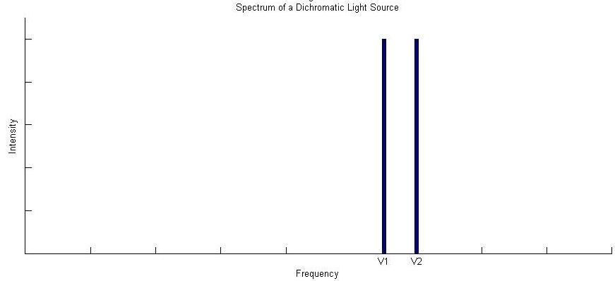
Imagine a light source that emits only two discreet frequencies of light \(\bar{ u_1}\) and \(\bar{ u_2}\) of equal intensity (Figure 1).
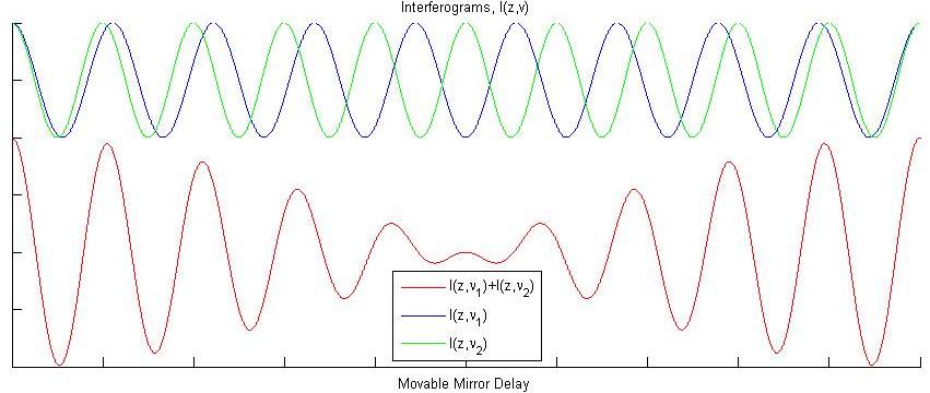
Now imagine we place an absorbing sample in our interferometer, and that it absorbs light at either \(\bar{ u_1}\) or \(\bar{ u_2}\), although we do not know which one yet. The result on the measured interferogram is given in blue in Figure 3 (with the reference interferogram from Figure 2 given in green).
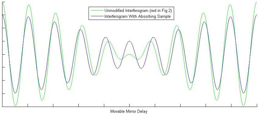
These two interferograms are all we need from the instrument! Now comes the FT of the FTIR. Fourier transforms will be covered in more detail in the next section. For now just think of it as a black box function in which you plug in an interferogram and get out a spectrum. Figure 1, therefore, is the Fourier transform of the red interferogram in Figure 2. Performing a Fourier transform on the measured blue interferogram in Figure 3 gives the spectrum in Figure 4.
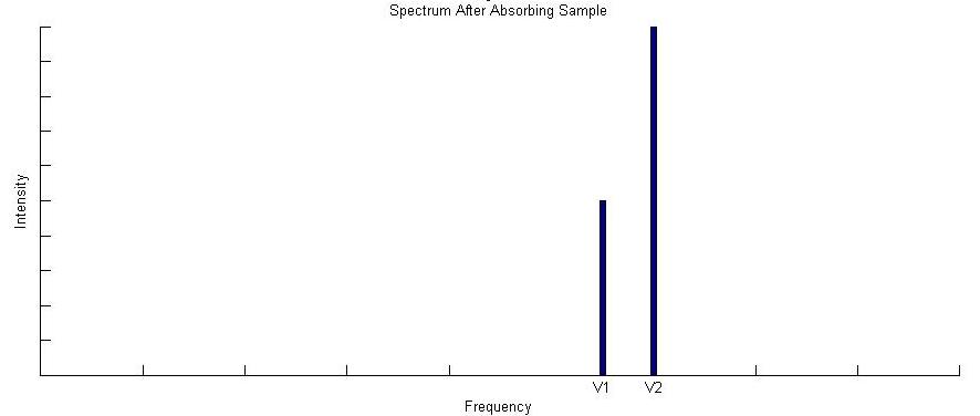
By comparing the spectrum in Figure 4 to Figure 1, we can immediately deduce that our absorbing sample absorbs light at frequency \(\bar{ u_1}\), and the FTIR spectrometer has done its job. Fundamentally that is all there is to it. The FTIR spectrometer takes light of various wavelengths, and measures an reference interferogram. You then place your absorbing sample into the interferometer and measure the interferogram again. Finally you Fourier transform both interferograms, and compare the spectra to determine what frequencies of light the sample is absorbing.
The next sections work on developing a more complete description of the the measured spectra, and the instrument nuances that factor into your data manipulation. To do this, however, we will need to open up the black box we put the Fourier transform in, and get an idea of how it works.
Fourier Transforms
From the previous section we saw that Fourier Transforms (in the context of FTIR) take an interferogram and produce a spectrum. The last section also implicitly presented the idea that the interferogram measured by an FTIR interferometer is just the sum of the interferograms of all the constituent frequencies present in the source. The Fourier transform, then, must break down the interferogram to reveal these constituent frequencies telling us which are present and in what amount.
To make this as easy on ourselves as possible, the first step we can take is to shift a maximum value of the interferogram to the origin. This ensures that it will be inherently cosine in nature (cos(0) = 1 vs sin(0)=0). As we will see in the phase error section below, this also assumes a symmetric interferogram, which you will not generally have.
Now that our interferogram is symmetric about the origin, all we need to do (all the Fourier transform does) is product it with a large variety of cosines to see which fit. The idea behind this is quite simple. If we luck out and hit our interferogram with a cosine that exactly matches one of our constituent frequencies, we will get a \(\cos^2(x)\) which is positive for all values of x. If we add up our \(\cos^2(x)\) over all values of x we will get a large positive value.
All other cosines not equal to a cosine present in the interferogram will be positive for some x and negative for the rest. Adding the positive and the negative together for all x will give zero. Lets look at the simple case of an \(\cos(x)\) interferogram tried against three different cosines and one cosine that exactly matches (Figure 5):
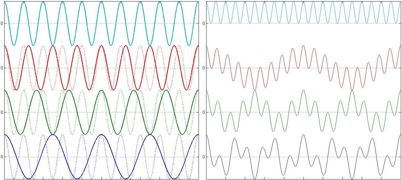
As you can see in 5b every cosine but the one that exactly matches the interferogram spends an equal amount of time above and below 0; such that if we were to add up the area under these curves, only the top (teal) one would be non-zero. We can also look at various test cosines against the interferogram from Figure 2, again ending in a cosine that matches one of the two frequencies present in that interferogram (Figure 6):
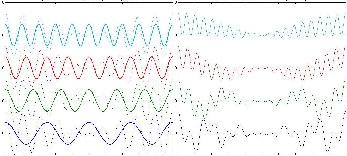
Again in Figure 6 we can see that only when we get close to a cosine present in the interferogram (teal is equal to \( u_2\)) does the area become large and positive. With this in mind we are now able to write the general form of our cosine Fourier Transform, namely, all we were doing above is taking the product of our interferogram, \(I(z)\), with a test cosine, \(\cos(2 \pi \bar{ u} z)\), and determining the area:
\[B(\bar{ u}) = \int_{-\infty}^{\infty} I(z) \cos(2 \pi \bar{ u} z) \,d z \label{3-1} \]
Figures 5 and 6 show the product \(I(z) \cos(2 \pi \bar{ u} z)\), in a small window of delay, and for only four test function wavelengths (\(\bar{ u}\) in inverse centimeters \(cm^{-1}\)). Equation \(\ref{3-1}\), however, gives the total area for any test function wavelength that you ask for. To recover the spectra we need from the FITR spectrometer, we must evaluate Equation \(\ref{3-1}\) for a range of wavelengths that include those of the source. As you can imagine this would be a very resource intensive process. In practice a Fast Fourier Transform (FFT), it is a computing trick used that avoids performing a large number of integrals over all space. For more on FFTs go here. Also, when asymmetries are present in the interferogram you will need to perform a complex fourier transform in order to ultimately correct those asymmetries. This will be covered in the phase error section below. Aside from these details, this discussion gives a decent introduction to how Fourier transforms are used in FTIR.
Reconstructing a Measured Interferogram: Major Contributing Factors
Although the concepts developed so far are fundamental and useful, real interferograms used in FTIR spectroscopy don't look anything like Figure 2. This section will take a few steps towards developing an interferogram similar to one you would actually see measured in an FTIR spectrometer, and explain their sources. In the process we will develop all the tools we need to successfully analyze and deconstruct real interferograms produced from FTIR spectrometers.
Polychromatic Light Sources
So far all we have considered are monochromatic and dichromatic FTIR spectrometers that have allowed us to use very simple interferograms. It might occur to you, however, that such instruments would not be terribly useful. We would need our samples to just happen to absorb at whatever frequency of light we selected for our interferometer. Real FTIR spectrometers don't use just two frequencies, but a whole continuum of light typically generated from a black body source (more on instrumentation here).
To get an idea of what this looks like for an interferogram lets see what happens when 5 and 50 frequencies of light interfere with equal intensities (Figure 7):
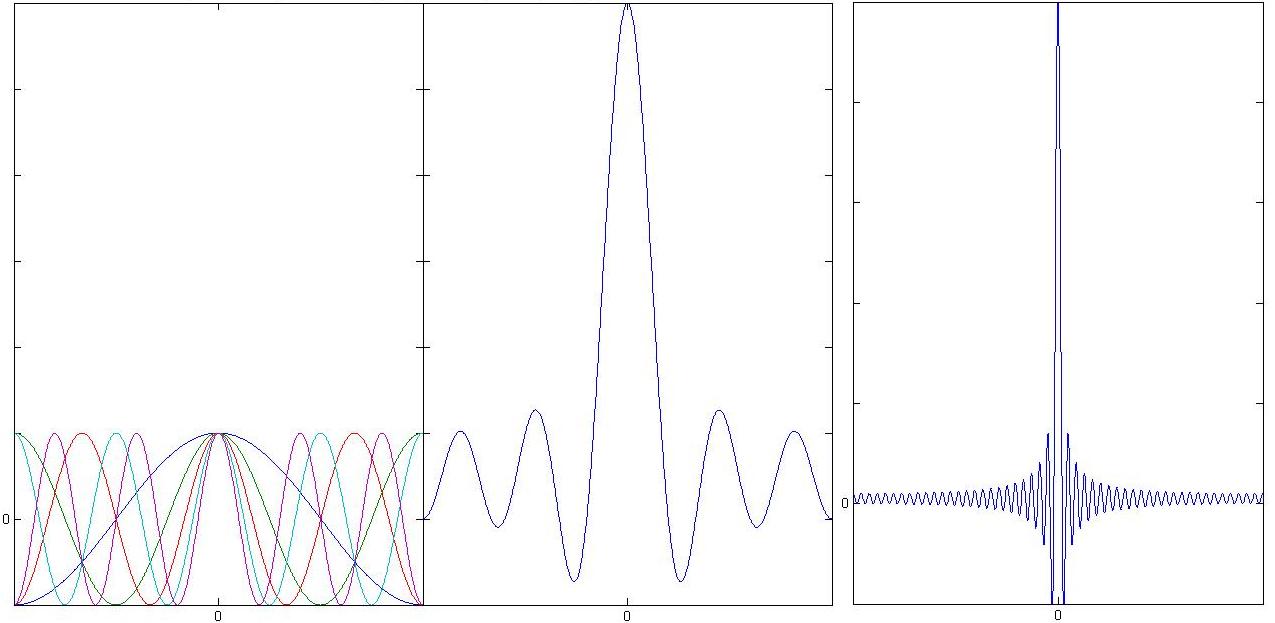
Figure 7b already has the well defined centerburst of an actual interferogram. We have, however, left out a very important feature of blackbody sources. A blackbody source emits radiation in a continuous envelope described by Planks law, and this modifies our interferogram in a significant way (Figure 8).
At this point it is worth noting that the interferograms of each wavelength add in phase at zero delay (Figure 7a). This might immediately seem strange considering FTIR interferometers use incoherent light sources. Because we are making use of a Michelson Interferometer, however, zero delay means the path lengths to the movable and fixed mirrors are equal. The electric fields at every wavelength are therefore in phase with themselves at zero delay. Because the detector only measures Intensity (proportional to electric field squared) it will therefore read a maximum for zero delay, consistent with what is depicted in Figure 7a and 7b.
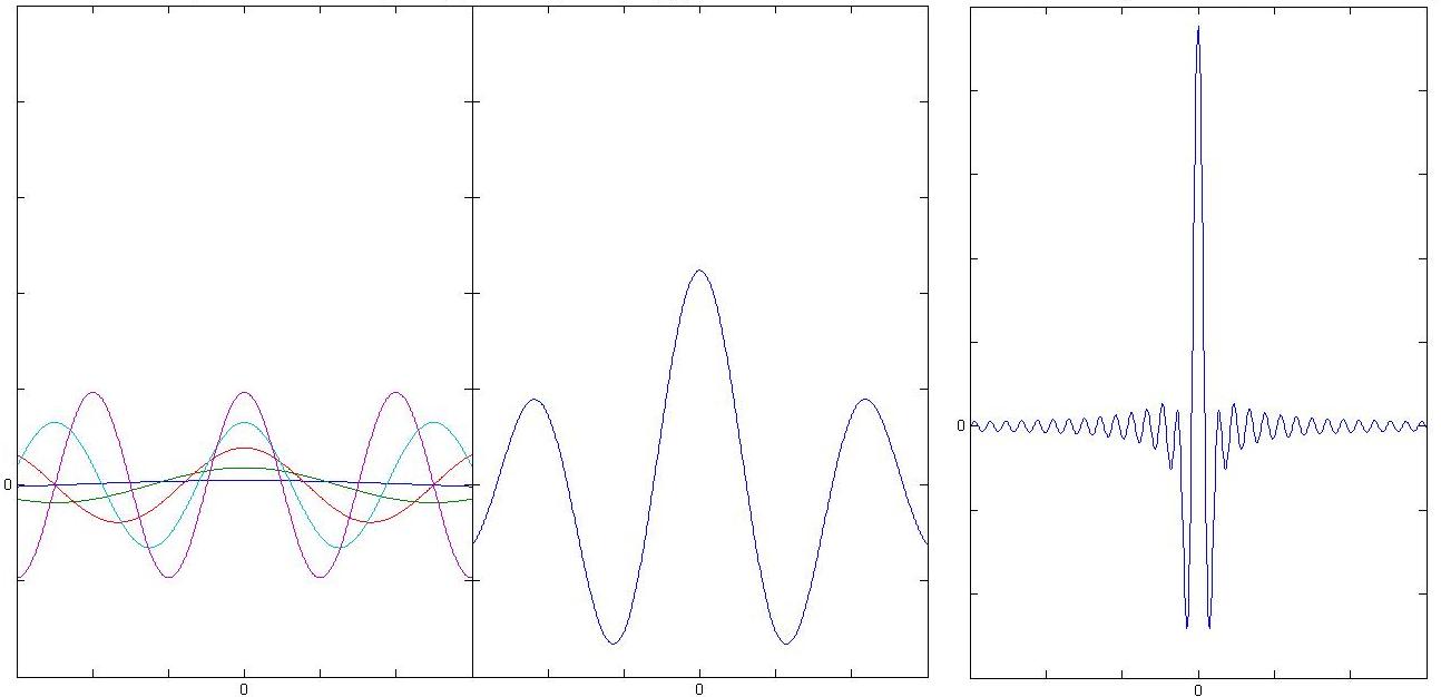
In Figure 8a you can clearly see the effect of the Planck distribution on the amplitudes of each individual frequency, and in 8b the result of a large number of these adjusted frequencies interfering. These interferograms are generated by the product
\[\dfrac{\alpha \bar{ u}^3}{\exp(\beta \bar{ u})-1} \cos(2 \pi z \bar{ u}) \nonumber \]
shown over a small range of z about the origin. \(\alpha\) and \(\beta\) are constants given physically by the Planck distribution. To reveal the full Interferogram intensity distribution, you must integrate over all possible frequencies \(\bar{ u}\):
\[ I(z) = \int_{-\infty}^{\infty}\dfrac{\alpha \bar{ u}^3}{\exp(\beta \bar{ u})-1} \cos(2 \pi z \bar{ u})\,d {\bar{ u}} \nonumber \]
which is a Fourier transform of the general form:
\[ I(z) = \int_{-\infty}^{\infty}B(\bar{ u}) \cos(2 \pi z \bar{ u}) \,d {\bar{ u}} \label{4.1-1} \]
Equation \(\ref{4.1-1}\) is known as the Fourier transform pair of Equation \(\ref{3-1}\). Remember in this section we are essentially working backwards to generate the interferogram you would measure from an FTIR spectrometer. The general problem is to be given \(I(z)\) from the instrument and use it to produce \(B(\bar{ u})\)
Instrument Line Shape
Equation \(\ref{4.1-1}\) shows us that ideally we could move our movable mirror from \(- \infty\) to \(\infty\) to measure an intensity interferogram. Unfortunately our mirror only has a finite range of motion, and this puts a limit on the resolution obtainable with the spectrometer. The finite range of motion in the mirror coordinate, \(z\), is equivalent to taking an entire intensity interferogram \(I(z)\) from \(- \infty\) to \(\infty\) and truncating it so that it only retains its values in the range accessible by the mirror (call it \(2 \Delta\)).
Mathematically this can be accomplished by using a step function \(D(z)\) that is one over the range of the mirror and zero otherwise.
\(D(z) = 1\) for \(-\Delta \leq z \leq \Delta\)
\(D(z) = 0\) for \(z > | \Delta |\)
This truncation function \(D(z)\) is acting on the intensity interferogram \(I(z)\), such that recovering the spectrum \(B(\bar{ u})\) is now a more complicated affair. Namely Equation \(\ref{3-1}\) now reads:.
\[B(\bar{ u}) = \int_{-\infty}^{\infty} I(z) D(z) \cos(2 \pi \bar{ u} z) \,d z\label{4.2-1} \]
Fortunately it is the case the the Fourier transform of the product of two functions is the convolution of the Fourier transform of each individual function. To evaluate Rquation \(\ref{4.2-1}\), then, we need the Fourier transform of \(D(z)\). The Fourier transform of \(D(z)\) is done in most detailed discussions of Fourier transforms, and is:
\[FT[D(z)] = 2 \Delta sinc (2 \pi \bar{ u} \Delta) \nonumber \]
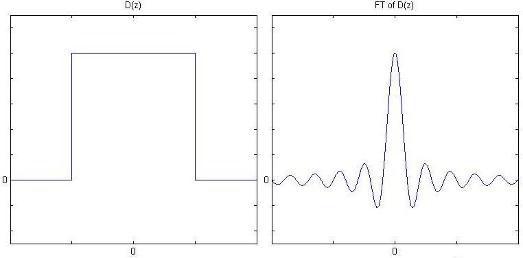
Figure 9: (Left) The truncation function \(D(z)\) is shown. (Right) \(D(z)\)'s Fourier Transform which will be convolved with the spectrum \(B(\bar{ u})\)
The consequence of this truncation is evident in the final spectrum \(B_{final}(\bar{ u})\). Namely we must now convolve the ideal spectrum from Equation \(\ref{3-1}\) with the sinc function to yield our final spectrum. Mathematically:
\[B_{final}(\bar{ u}) = \int_{-\infty}^{\infty} B(\bar{ u}') 2 \Delta sinc (2 \pi \Delta (\bar{ u}-\bar{ u}')) \,d \bar{ u}' \label{4.2-2} \]
We have now seen that having a movable mirror with finite travel introduces the convolution of a sinc function to our final spectrum. So what does this do to the resolution of our spectrometer? From Equation \(\ref{4.2-2}\) you can see that a convolution is analogous to overlapping the two functions (the sinc and \(B(\bar{ u})\)) at \(\bar{ u}=\bar{ u}'\) and then sliding \(B(\bar{ u})\) back and forth taking the product at every point.
The absolute cleanest spectrum we can have is perfectly monochromatic light. In this case \(B(\bar{ u})\) is a delta function spiked at \( u_1\). Convolving this with with \(2 \Delta sinc (2 \pi \bar{ u} \Delta)\) gives the shifted sinc function pictured to the on the far right of Figure 10.
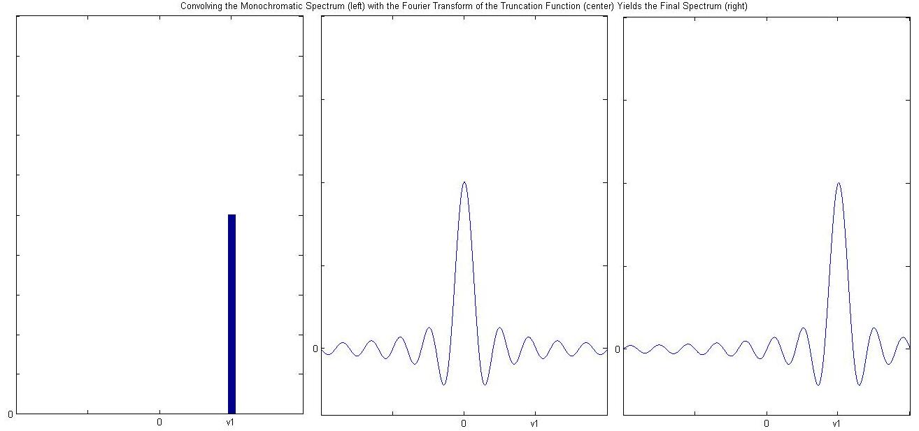
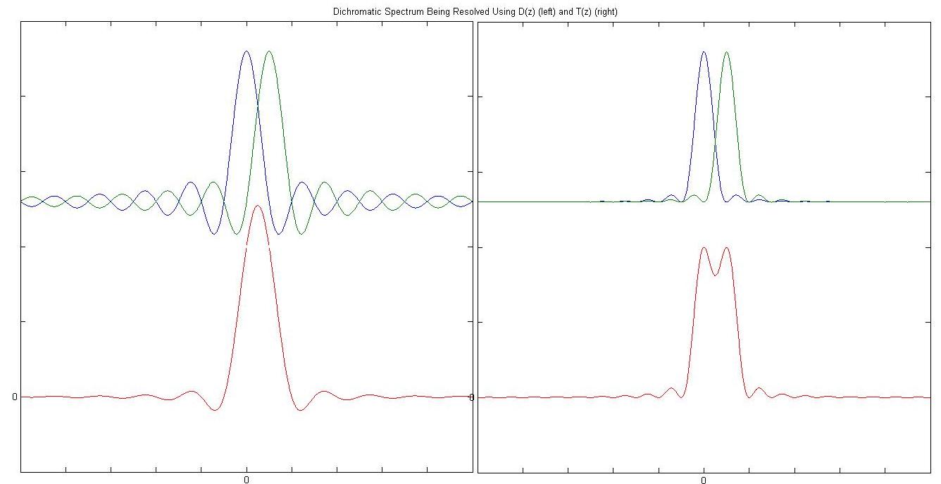
The far right of Figure 10 shows that even with perfectly monochromatic light, the fact that we have limited travel with the movable mirror results in a broadened peak in the final spectrum, thus putting an upper limit on the resolution (Figure 11). All is not lost, however. We can artificially manipulate this instrument line shape, \(D(z)\), to improve our resolution, by using a new function that removes the feet to the left and right of the sinc max. In Greek, "A podos" means without feet.
Apodization
Previously we used the the instrument line shape \(D(z)\) as essentially a window into the spectrum where the widest we could open the window is determined by the distance achievable with the movable mirror. Once we have that information, however, we are free to crop the window in any manner we see fit thus artificially manufacturing an instrument line shape that we might find more favorable. As one example of this consider the triangular window \(T(z)\):
\[T(z) = 1 - \left|\dfrac{z}{\Delta} \right| \nonumber \]
for \(-\Delta \leq z \leq \Delta\)
\[T(z) = 0 \nonumber \]
for \(z > | -\Delta |\)
As it turns out the Fourier transform of \(T(z)\) is:
\[FT[T(z)] = \Delta sinc^2 (2 \pi \bar{ u} \Delta) \nonumber \]
The benefit of choosing this instrument line shape over the unmodified \(D(z)\) can be clearly seen in Figure 11.
Instrument Resolution
Let's return for a moment to our dichromatic interferometer to get an idea of what the maximum possible resolution obtainable is. In the case of two frequencies of light, the recurrence of constructive interference depends on the difference between the two frequencies, namely:
\[z_{constructive} =\dfrac{1}{\bar{ u_2} - \bar{ u_1}} =\dfrac{1}{\Delta\bar{ u}} \nonumber \]
So what is the smallest separation between two frequencies we can detect? Looking at the above equation its apparent that a small \(\Delta\bar{ u}\) requires a large z. So the maximum resolution depends on the amount of travel in the movable mirror, z. In fact, the very smallest unit of frequency on the frequency axis after Fourier transformation of \(I(z)\) will be
\[\Delta \bar{ u}_{min} = \dfrac{1}{\Delta z_{max}} \nonumber \]
This intuitive approach actually stands up to more rigorous derivations, and shows us that our maximum frequency resolution depends on total travel of the movable mirror. But how is this usually measured?
To continue, we are going to need to know a little something about the instrumentation. In order to measure z we can make use of a single frequency source of light (a laser) by sending it through our interferometer and watching its interference. Every time we see completely constructive interference at the wavelength of our laser, we can count that as a mark on our z axis. The separation between any two marks on the z axis are therefore:
\[\Delta z = \lambda \nonumber \]
Where \(\lambda\) is the wavelength of the laser. The maximum travel of the movable mirror, \(\Delta z_{max}\), can therefore be measured as
\[\Delta z_{max} = N \lambda \nonumber \]
where \(N\) is the total number of points measured for the z axis.
We are now ready to rewrite our frequency and distance axis completely in terms of our laser wavelength. Every point along our z axis is just some integer multiple of the smallest measurable step along z, namely:
\[z = n \lambda \label{4.2.2-1} \]
where \(n\: =\: 0,\: 1,\: 2,\: ... N-1\)
and
\[ \begin{align} \bar{ u} &= k \Delta \bar{ u_{min}} \\[4pt] &= \dfrac{k}{\Delta z_{max}} \label{4.2.2-2} \\[4pt] &= \dfrac{k}{N \lambda} \end{align} \]
where \(k\: =\: 0,\: 1,\: 2,\: ... N-1\)
Phase Errors
So far it has been assumed that the interferograms are a result of perfectly symmetric interference as in Figure 8. In real FTIR spectrometers, however, it is generally the case that each wavelength is pulled slightly out of phase with respect to its neighbors. These phase errors can be introduced in a number of ways, but are often the result of electronic filters. Mathematically this can be represented by simply adding a phase term into Equation \(\ref{4.1-1}\).
\[I(z) = \int_{-\infty}^{\infty} B(\bar{ u}) \cos(2 \pi \bar{ u} z-\phi_{\bar{ u}}) \,d \bar{ u} \label{ 4.3-1} \]
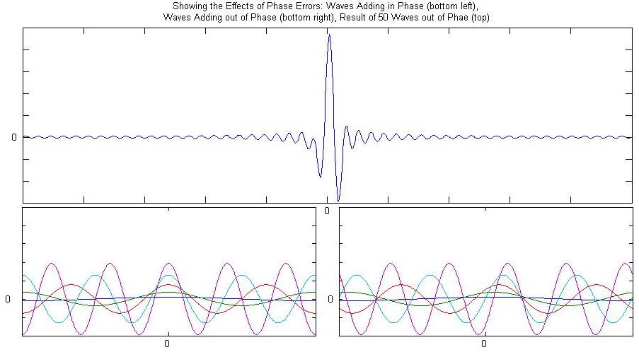
The asymmetries introduced by these phase errors can be accounted for using a series of sine waves in a similar way to the Fourier Transform section above. The only difference is instead of using cosine waves we would now use sine waves to take account of the asymmetric elements. Such sine waves, however, do not represent anything physically useful in our spectrometer, so we need to get rid of them by shifting all of our cosine interferograms back to constructively interference at z = 0.
To do this we need a way to independently evaluate the symmetric and asymmetric components of our interferogram using cosines and sines respectively. As it turns out we can use a nicely compact notation to keep track of our two components independently. By use of Euler's formula
\[ \cos{\theta} - i \sin{\theta} = e^{-i \theta} \nonumber \]
Equation \(\ref{4.3-1}\) can be rewritten as
\[I(z) = \int_{-\infty}^{\infty} B(\bar{ u}) e^{-2 \pi i \bar{ u}z} \,dz \label{4.3-2} \]
Equation \(\ref{4.3.2}\) is known as a complex Fourier transform, its Fourier transform pair being
\[B(\bar{ u}) = \int_{-\infty}^{\infty} I(z) e^{-2 \pi i \bar{ u}z} \,d z \label{4.3-3} \]
Given a intensity spectrum \(I(z)\), then, we can perform the complex Fourier transform according to equation \(\ref{4.3-3}\) which gives us a complex spectrum, \(B'(\bar{ u})\)
\[B'(\bar{ u}) = Re(\bar{ u}) +i Im(\bar{ u}) \nonumber \]
From here it is useful to draw out \(B'(\bar{ u})\) in the complex plane (Figure 13). By changing coordinates from \(B'(\bar{ u}) = Re(\bar{ u}) +i Im(\bar{ u})\) to \(B'(\bar{ u}) = r\cos(\phi_{\bar{ u}})+i r\sin(\phi_{\bar{ u}})\) we can apply Euler's formula and obtain
\[B' (\bar{ u}) = r e^{i \phi_{\bar{ u}}} \label{4.3-4} \]
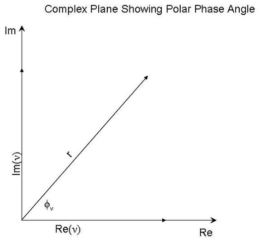
Figure 13: Showing the vector \(B'(\bar{ u})\) in the complex plane along with its polar angle \(\phi_{\bar{ u}}\) and radius r.
r is is also known as the magnitude spectrum, \(| B(\bar{ u}) |\), and is obtained by simply applying the Pythagorean theorem in Figure 13:
\[r^2 \equiv | B(\bar{ u}) |^2 = Re^2(\bar{ u})+Im^2(\bar{ u}) \nonumber \]
And so by equation \(\ref{4.3-4}\), the real and imaginary spectra are simply related by our frequency dependent phase angle \(\phi_{\bar{ u}}\) according to
\[B'(\bar{ u}) = | B(\bar{ u}) |e^{i \phi_{\bar{ u}}} \label{4.3-5} \]
Rearranging Equation \(\ref{4.3-5}\) and keeping only real terms (our final spectrum is real) we can find a phase corrected equation for \(B(\bar{ u})\)
\[B(\bar{ u}) = Re(\bar{ u})\cos{\phi_{\bar{ u}}} + Im(\bar{ u})\sin{\phi_{\bar{ u}}} \label{4.3-6} \]
Almost there! Equation \(\ref{4.3-6}\) gives us a phase corrected spectrum. All that is left to do is determine \(\phi_{\bar{ u}}\). Again referring to Figure 13 all we need is a little trigonometry
\[\tan{\phi_{\bar{ u}}} = \dfrac{Im(\bar{ u})}{Re(\bar{ u})} \nonumber \]
or
\[\phi_{\bar{ u}} = \arctan{ \dfrac{Im(\bar{ u})} {Re(\bar{ u})} } \label{4.3-7} \]
And so Equations \(\ref{4.3-6}\) and \(\ref{4.3-7}\) will phase correct our spectrum.
Deconstructing a Measured Interferogram to Recover the Absorption Spectrum
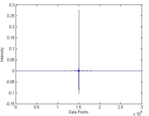
From section 4 we now have the majority of the tools we need to understand how an interferogram is processed into an absorption spectrum. The Mertz method is one of the more popular techniques for doing this. To illustrate it, lets process a real spectrum using only the tools we have developed so far. The interferogram measured (Figure A) is of air that was enhanced by breathing into it (literally). Our processed absorption spectrum, therefore, should include things like \(CO_2\) when compared to a normal air background.
Mertz Method
Ok lets process the spectrum in Figure A using the Mertz method.
Symmetrize
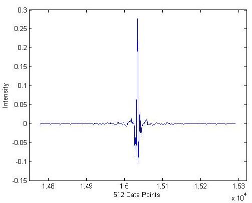
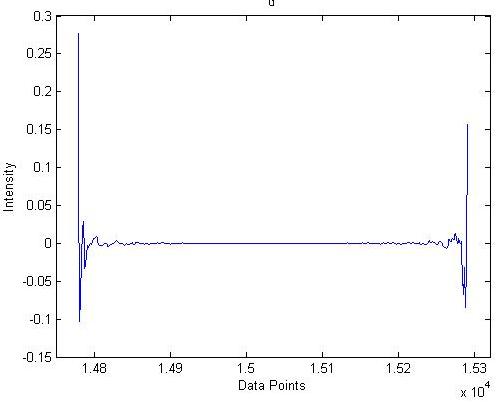
In order to phase correct our spectrum, we are going to need a small symmetric region about the centerburst, say 512 data points. We will later interpolate our extracted phase curve to full resolution. Figure B shows our small region about the centerburst.
Apodize
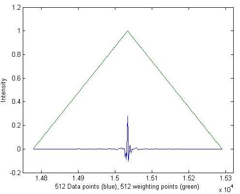
Next we modify our interferogram using an apodization function (see section 4.2.1). In this case we will use a triangular apodization function (Figure C).
Zero the Centerburst
Now we can rotate our spectrum to appear as the red curve in Figure 2, which helps the Fourier transform we are about to take be more meaningful (Figure D).
Fourier Transform
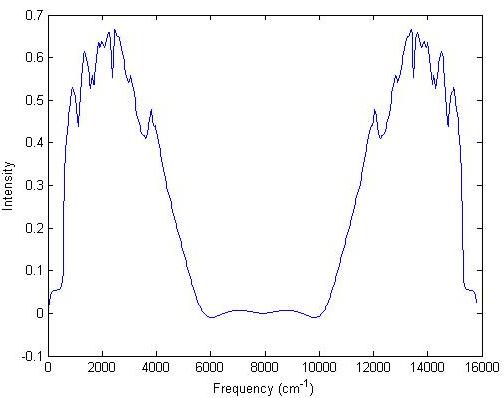
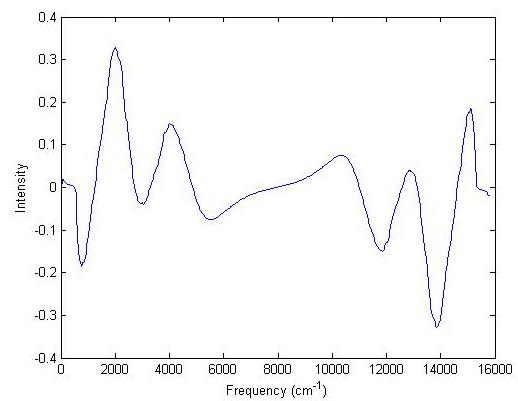
Notice that Figure B resembles the top of Figure 12, namely there are asymmetries (chirping) indicative of phase variations. We therefore need to take the complex Fourier transform according to Equation \(\ref{4.3-3}\), from which we get real (Figure E) and imaginary (Figure F) parts. The frequency axis is given by Equation \(\ref{4.2.2-2}\) using a HeNe laser wavelength for \(\lambda\).
Extract the Phase Curves
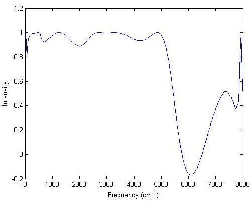
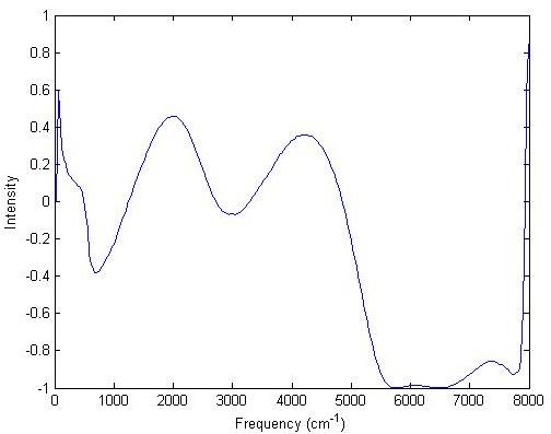
Using Equation \(\ref{4.3-7}\) we can now compute the phase curve by taking the arctangent of the ratio of Figures E and F (Figure G). The phase curves, like the transforms in Figures E and F, are symmetric, so only half needs to be shown.
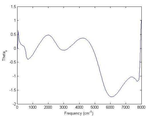
We are going to need the cosine (Figure H) and sine (Figure I) of the total phase cure in Figure G in order to phase correct our interferogram according to Equation \(\ref{4.3-6}\).
To use these curves the final step is toto interpolate from 512 to the full 30064 data points of the original data set.
Switch Back to Full Spectrum: Zero the Centerburst, Rotate, and Fourier Transform as Above
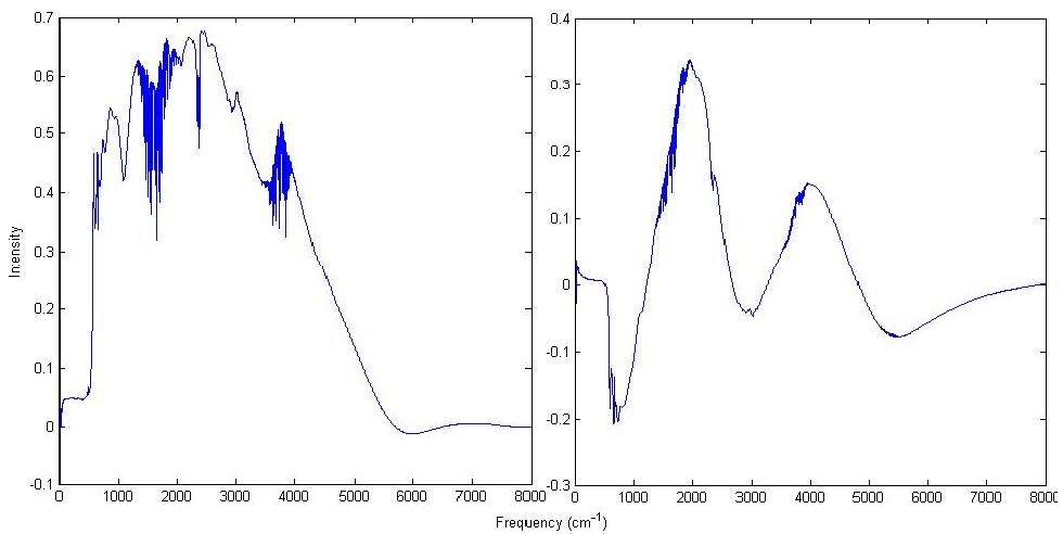
Following the same procedure as in Figures C, D, (E-F), for the full spectrum gives Figure J. Again only half is shown of both the real and symmetric components because they are symmetric about 8000 \(cm^{-1}\).
Phase Correct
We can now phase correct. Multiplying the left of Figure J with Figure H yields the left of Figure K (below), and multiplying the right of Figure J with Figure I yields the right of Figure K (below).
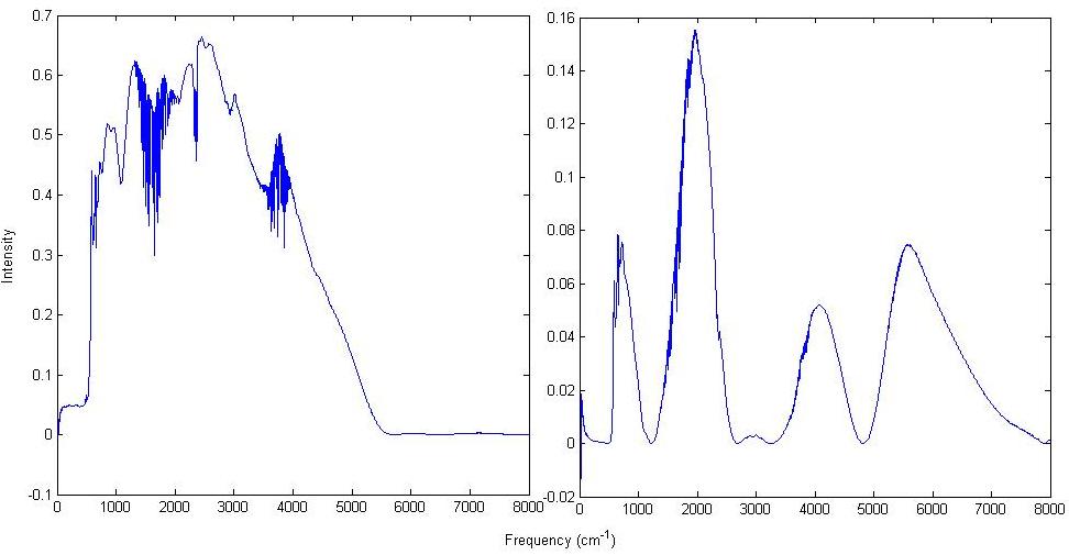
Figure K: Phase corrected real (left) and imaginary (right) parts of the Fourier transform of the full interferogram. The left is given by \(Re(\bar{ u})\cos{\theta_{\bar{ u}}}\) and the right is given by \(Im(\bar{ u})\sin{\theta_{\bar{ u}}}\).
Adding these together as according to equation 4.3-6 gives the phase corrected spectrum in Figure L.
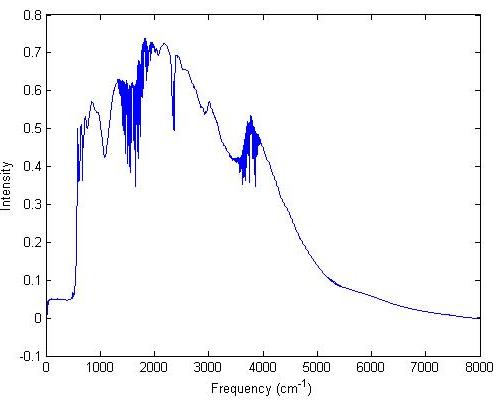
Ratio to the Reference Spectrum
All that is left to do is repeat everything for the background spectrum, and then ratio the result to Figure L. This produces the absorption spectrum in Figure M.
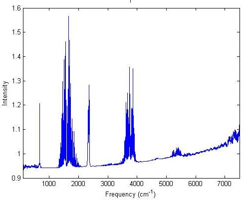
A few things have not been covered (zero filling) but as is apparent in Figure M, this works quite well to explain how the Mertz method, and FTIR spectrometers in general, work.
Reproduce the top of Figure 12 using matlab.
Solution
Possible solution:
x = [-5:.01:5];
v = [0:.1:5];
phase=(.01).*v.^2;
Ix = ((.001).^3./(exp((.001)-1))*cos(2*pi*x*(.001)));
for i=2:(length(v))
Ix = [Ix + ((v(i)).^3./(exp(v(i))-1))*cos(2*pi*x*(v(i))-phase(i)*2*pi)];
end
plot(x,Ix)
Perform the Mertz Method on the interferogram file "75_AIR.txt" with its background "75_BG.txt" (in the files tab below). Use the HeNe wavelength 63.3 microns, and the built in matlab FFT for the fourier transform.
Solution
Possible Solution
%Import the Data
data = importdata('75_BG.txt');
x = data(:,1);
Ix = -1*data(:,2);
%Extract 512 points about the centerburst
[maxval centerburst] = max(abs(Ix));
Ixshort = Ix(centerburst-255:centerburst+256);
xshort = x(centerburst-255:centerburst+256);
%Make Apodization function
apod = [1-abs(xshort - xshort(256))./((.5).*length(xshort))];
negapod = find(apod < 0);
apod(negapod) = [0];
%apodize the low res spectrum
Ixshortapod = Ixshort.*apod;
%Rotate it so the centerburst is at zero
Ixshortapodrot = [Ixshortapod(256:end); Ixshortapod(1:255)];
%FT
bprime = fft(Ixshortapodrot);
%Create frequency axis
freqfactor = 1/(length(xshort)*6.33*10^(-5))
v = [1:length(xshort)].*freqfactor;
v = v';
%Break down FT into Real and Imaginary parts
bprimereal = real(bprime);
bprimeimag = imag(bprime);
%determine thetav Note: atan() only uses two quadrants, we need all four
thetav = atan2(bprimeimag, bprimereal);
%interpolate thetav to full resolution
fullthetav = interp1(xshort,thetav,linspace(xshort(1), xshort(end),length(x)));
fullthetav = fullthetav';
%Get phase correction terms from thetav
fullcosterm = cos(fullthetav);
fullsinterm = sin(fullthetav);
%Now switch to full Interferogram
%Full apodization function
apod1 = [1-abs(x - x(centerburst))./((.5).*length(x(centerburst:end)))];
negapod1 = find(apod1 < 0);
apod1(negapod1) = [0];
Ixapod = Ix.*apod1;
%Rotate
Ixapodrot = [Ixapod(centerburst:end); Ixapod(1:(centerburst-1))];
%FT
bprimefull = fft(Ixapodrot);
bprimefullreal = real(bprimefull);
bprimefullimag = imag(bprimefull);
%full freq axis
fullfreqfactor = 1/(length(x)*6.33*10^(-5));
fullv = [1:length(x)].*fullfreqfactor;
fullv = fullv';
%Phase correct
fullbetadjreal = bprimefullreal.*fullcosterm;
fullbetadjimag = bprimefullimag.*fullsinterm;
fullbetadjBG = fullbetadjreal + fullbetadjimag;
%fullbetadjBG is the phase corrected background spectrum.
References
- Griffiths, Peter R., (1986). Fourier Transform Infrared Spectrometry. John Wiley & Sons, Inc.
- Mackenzie, M. W., (1988). Advances in Fourier Transform Infrared Spectroscopy. John Wiley & Sons, Inc.
- McCurdy, C. W. Notes and Problem Set from UC Davis Class.

