
3.3.4: Assembling a complete MO diagram
- Page ID
- 202270
\( \newcommand{\vecs}[1]{\overset { \scriptstyle \rightharpoonup} {\mathbf{#1}} } \)
\( \newcommand{\vecd}[1]{\overset{-\!-\!\rightharpoonup}{\vphantom{a}\smash {#1}}} \)
\( \newcommand{\id}{\mathrm{id}}\) \( \newcommand{\Span}{\mathrm{span}}\)
( \newcommand{\kernel}{\mathrm{null}\,}\) \( \newcommand{\range}{\mathrm{range}\,}\)
\( \newcommand{\RealPart}{\mathrm{Re}}\) \( \newcommand{\ImaginaryPart}{\mathrm{Im}}\)
\( \newcommand{\Argument}{\mathrm{Arg}}\) \( \newcommand{\norm}[1]{\| #1 \|}\)
\( \newcommand{\inner}[2]{\langle #1, #2 \rangle}\)
\( \newcommand{\Span}{\mathrm{span}}\)
\( \newcommand{\id}{\mathrm{id}}\)
\( \newcommand{\Span}{\mathrm{span}}\)
\( \newcommand{\kernel}{\mathrm{null}\,}\)
\( \newcommand{\range}{\mathrm{range}\,}\)
\( \newcommand{\RealPart}{\mathrm{Re}}\)
\( \newcommand{\ImaginaryPart}{\mathrm{Im}}\)
\( \newcommand{\Argument}{\mathrm{Arg}}\)
\( \newcommand{\norm}[1]{\| #1 \|}\)
\( \newcommand{\inner}[2]{\langle #1, #2 \rangle}\)
\( \newcommand{\Span}{\mathrm{span}}\) \( \newcommand{\AA}{\unicode[.8,0]{x212B}}\)
\( \newcommand{\vectorA}[1]{\vec{#1}} % arrow\)
\( \newcommand{\vectorAt}[1]{\vec{\text{#1}}} % arrow\)
\( \newcommand{\vectorB}[1]{\overset { \scriptstyle \rightharpoonup} {\mathbf{#1}} } \)
\( \newcommand{\vectorC}[1]{\textbf{#1}} \)
\( \newcommand{\vectorD}[1]{\overrightarrow{#1}} \)
\( \newcommand{\vectorDt}[1]{\overrightarrow{\text{#1}}} \)
\( \newcommand{\vectE}[1]{\overset{-\!-\!\rightharpoonup}{\vphantom{a}\smash{\mathbf {#1}}}} \)
\( \newcommand{\vecs}[1]{\overset { \scriptstyle \rightharpoonup} {\mathbf{#1}} } \)
\( \newcommand{\vecd}[1]{\overset{-\!-\!\rightharpoonup}{\vphantom{a}\smash {#1}}} \)
\(\newcommand{\avec}{\mathbf a}\) \(\newcommand{\bvec}{\mathbf b}\) \(\newcommand{\cvec}{\mathbf c}\) \(\newcommand{\dvec}{\mathbf d}\) \(\newcommand{\dtil}{\widetilde{\mathbf d}}\) \(\newcommand{\evec}{\mathbf e}\) \(\newcommand{\fvec}{\mathbf f}\) \(\newcommand{\nvec}{\mathbf n}\) \(\newcommand{\pvec}{\mathbf p}\) \(\newcommand{\qvec}{\mathbf q}\) \(\newcommand{\svec}{\mathbf s}\) \(\newcommand{\tvec}{\mathbf t}\) \(\newcommand{\uvec}{\mathbf u}\) \(\newcommand{\vvec}{\mathbf v}\) \(\newcommand{\wvec}{\mathbf w}\) \(\newcommand{\xvec}{\mathbf x}\) \(\newcommand{\yvec}{\mathbf y}\) \(\newcommand{\zvec}{\mathbf z}\) \(\newcommand{\rvec}{\mathbf r}\) \(\newcommand{\mvec}{\mathbf m}\) \(\newcommand{\zerovec}{\mathbf 0}\) \(\newcommand{\onevec}{\mathbf 1}\) \(\newcommand{\real}{\mathbb R}\) \(\newcommand{\twovec}[2]{\left[\begin{array}{r}#1 \\ #2 \end{array}\right]}\) \(\newcommand{\ctwovec}[2]{\left[\begin{array}{c}#1 \\ #2 \end{array}\right]}\) \(\newcommand{\threevec}[3]{\left[\begin{array}{r}#1 \\ #2 \\ #3 \end{array}\right]}\) \(\newcommand{\cthreevec}[3]{\left[\begin{array}{c}#1 \\ #2 \\ #3 \end{array}\right]}\) \(\newcommand{\fourvec}[4]{\left[\begin{array}{r}#1 \\ #2 \\ #3 \\ #4 \end{array}\right]}\) \(\newcommand{\cfourvec}[4]{\left[\begin{array}{c}#1 \\ #2 \\ #3 \\ #4 \end{array}\right]}\) \(\newcommand{\fivevec}[5]{\left[\begin{array}{r}#1 \\ #2 \\ #3 \\ #4 \\ #5 \\ \end{array}\right]}\) \(\newcommand{\cfivevec}[5]{\left[\begin{array}{c}#1 \\ #2 \\ #3 \\ #4 \\ #5 \\ \end{array}\right]}\) \(\newcommand{\mattwo}[4]{\left[\begin{array}{rr}#1 \amp #2 \\ #3 \amp #4 \\ \end{array}\right]}\) \(\newcommand{\laspan}[1]{\text{Span}\{#1\}}\) \(\newcommand{\bcal}{\cal B}\) \(\newcommand{\ccal}{\cal C}\) \(\newcommand{\scal}{\cal S}\) \(\newcommand{\wcal}{\cal W}\) \(\newcommand{\ecal}{\cal E}\) \(\newcommand{\coords}[2]{\left\{#1\right\}_{#2}}\) \(\newcommand{\gray}[1]{\color{gray}{#1}}\) \(\newcommand{\lgray}[1]{\color{lightgray}{#1}}\) \(\newcommand{\rank}{\operatorname{rank}}\) \(\newcommand{\row}{\text{Row}}\) \(\newcommand{\col}{\text{Col}}\) \(\renewcommand{\row}{\text{Row}}\) \(\newcommand{\nul}{\text{Nul}}\) \(\newcommand{\var}{\text{Var}}\) \(\newcommand{\corr}{\text{corr}}\) \(\newcommand{\len}[1]{\left|#1\right|}\) \(\newcommand{\bbar}{\overline{\bvec}}\) \(\newcommand{\bhat}{\widehat{\bvec}}\) \(\newcommand{\bperp}{\bvec^\perp}\) \(\newcommand{\xhat}{\widehat{\xvec}}\) \(\newcommand{\vhat}{\widehat{\vvec}}\) \(\newcommand{\uhat}{\widehat{\uvec}}\) \(\newcommand{\what}{\widehat{\wvec}}\) \(\newcommand{\Sighat}{\widehat{\Sigma}}\) \(\newcommand{\lt}{<}\) \(\newcommand{\gt}{>}\) \(\newcommand{\amp}{&}\) \(\definecolor{fillinmathshade}{gray}{0.9}\)Please watch this video, and then read the text below and try the practice problems.
**There is an error at the end of the video - you should find O2 to be paramagnetic (not diamagnetic).
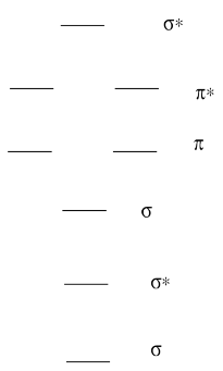
So far, we have looked at the ways in which pairs of atomic orbitals could combine to form molecular orbitals -- to form bonds. Just as we think of there being a progression of atomic orbitals from lowest energy to highest (1s, 2s, 2p, 3s...), we can organize these molecular orbitals by order of their energy.
To a great extent, the order of molecular orbitals in energy can be considered to follow from the order of the atomic orbitals from which they are constructed. There are some departures from that rule, sometimes, but that's the simplest place to start. So, in a molecule, the lowest-energy molecular orbitals would be the ones formed from the lowest-energy atomic orbitals, the 1s orbitals.
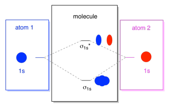
What we see here is a molecular orbital interaction diagram. The middle of the diagram is just the molecular orbital energy diagram. It is analogous to the atomic orbital energy diagram (which goes 1s, 2s, 2p, 3s...). The order of energy so far is σ1s, σ1s*. The sides of the diagram just refer back to where those molecular orbitals came from, with dotted lines to guide you from one place to another. Altogether, the picture says that the 1s orbital on one atom and the 1s orbital on the other atom can combine in two different ways, producing the lower-energy, bonding σ1s and the higher-energy, antibonding σ1s*.
Note that we have not added any electrons to that molecular orbital energy diagram yet, but when we do, we will just fill them in from the bottom up, just like we would an atomic orbital energy diagram.
The next lowest set of atomic orbitals is the 2s level. These spherical orbitals would combine very much like 1s orbitals, and we would get a similar diagram, only at a slightly higher energy level.
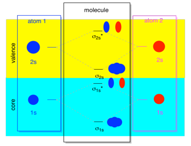
Most of the time, we aren't going to see both the σ1s and the σ2s displayed in the diagram. That's because if there are any 2s electrons, then those 1s electrons are really core electrons, not valence. They are buried a little deeper in the atom, and they don't play a very important role in bonding. Ignoring the core electrons is pretty common; if you recall, in atomic electron configurations we might write [He]2s22p4 instead of 1s22s22p4 for oxygen; we were ignoring the core. When we drew Lewis structures, we gave oxygen six electrons, rather than eight; we were ignoring the core.
In the context of MO, suppose we do have 2s electrons. That must mean that each atom has two 1s electrons of its own, for a total of four. When those four electrons are filled into the MO diagram from the bottom up, they will occupy both the bonding σ1s and the antibonding σ1s*. The effect of both those combinations being occupied is to cancel out the bonding; those two pairs of electrons remain non-bonding. So we can ignore them and we aren't really missing anything.
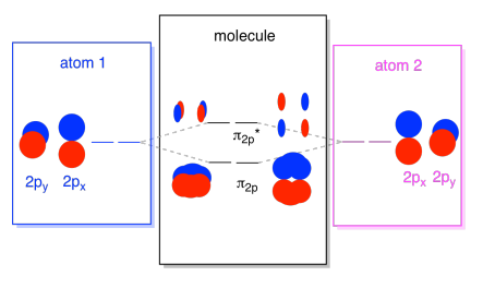
The 2s orbitals aren't the only ones in the second shell. There are also 2p orbitals. Remember, there are a couple of very different ways in which p orbitals can combine with each other, depending upon which axis they lie. If they do not lie parallel to each other -- that is, if they are perpendicular to each other, such as a px and a py -- then they cannot interact with each other at all. The pz on one atom could interact with the pz on the other atom, however, because they are parallel to each other.
Usually, we define the z axis as lying along the line between the two atoms we are looking at. Two pz orbitals would lie along that axis, each with a lobe extending into the space between the atoms, and each with another lobe extending away, in the other direction
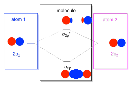
The resulting combinations are called σ because they do lie along the axis between the atoms (that's exactly what σ means, in terms of bonding). There is a σ combination, if the overlapping lobes are in phase with each other, and σ* combination, if those lobes are out of phase with each other. Because these new orbitals arise from the atomic 2p orbitals, we call them σ2p and σ2p*.
There are also those p orbitals that do not lie along the bond axis, or the axis between the two atoms. The px orbitals are perpendicular to the pz orbitals we just looked at, and therefore perpendicular to the axis between the bonds. However, they are still parallel to each other, and they can still form combinations. These two orbitals would form an in-phase combination and an out-of-phase combination.
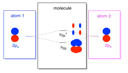
Note that the energetic separation between these two combinations is a little smaller that the gap between the σ2p and σ2p* levels. The difference is related to the degree of overlap between the atomic orbitals. The on-axis orbitals project strongly into the same space; they overlap a lot, and they interact strongly. The off-axis orbitals brush against each other, interacting less strongly, and resulting in smaller energetic changes. The gap between the π2p orbital and π2p* orbital is therefore much smaller than the one between the σ2p and σ2p* orbitals.
There are actually two of those off-axis p orbitals. In addition to the px set, we would have a py set. If the px set is in the plane of the screen, the py set has one orbital sticking out in front and one hidden behind. Nevertheless, the combinations between the two py orbitals are exactly the same as what we saw between the two px orbitals. They are just rotated into a perpendicular plane with respect to the px combinations.
We can put all of those 2p-based orbitals together in one diagram. It's starting to get a little more crowded, but this diagram is just a combination of the pieces we have already seen. Note that the px, py, and pz atomic orbitals all start out at the same energy (we have stacked them here so that you can still see the correlation between the atomic and molecular orbitals). That means that the π2p & π2p* orbitals will be "nested" between the σ2p & σ2p* orbitals.
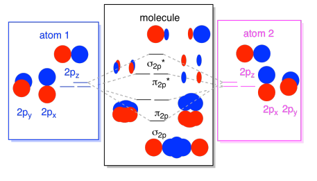
Finally, keeping in mind that the 2p orbitals are higher in energy than the 2s orbitals, we can combine those pictures into one diagram. Again, we have seen these individual pieces before; we are just assembling them now.
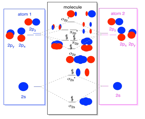
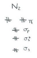
While we are at it, we can can add in the electrons. How? It's just the total number of valence electrons. For an example, we have used N2. Each nitrogen has five valence electrons, for a total of ten, so we have just filled in ten electrons, starting at the bottom of the molecular orbital energy level diagram. If this were another molecule, such as F2 or O2, we would construct the overall diagram in a similar way, but just use a different number of electrons.
The orbital picture we have described above is really just a potential picture of the electronic structure of dinitrogen (and any other main group or p-block diatomic). We won't get a real picture of dinitrogen's structure until we populate these potential levels with electrons.
- Only the energy levels with electrons have an effect on the energy (and behavior) of the molecule.
In other words, the energy of the electrons determines the behavior of the molecule. The other energy levels are only possibilities that remain unfulfilled.
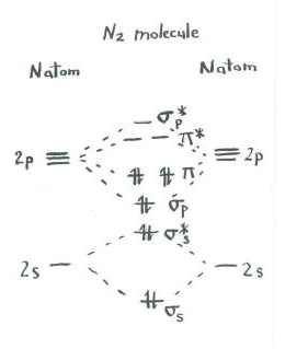
Think about the picture of dinitrogen.
- Each nitrogen has five valence electrons.
- There are a total of ten electrons.
- Two each go into the s s bonding and s s* antibonding levels. Remember, we kept these separate from the p set as a simplification.
- Two each go into the s p bonding and each of the p bonding levels.
The remaining orbitals (s p* antibonding and each of the p * antibonding levels) are unoccupied. These are imaginary levels that do not play a role in determining the energy of dinitrogen. In a real molecular orbital calculation, the electrons in these levels would contribute to the overall energy of the molecule.
We get additional information from this picture. For example, we can see the bond order in dinitrogen.
- Bond order is just the number of bonds between a pair of atoms.
- The bond order is one of several factors that influences the strength of the covalent bond.
- The higher the bond order, the more electrons are shared between the atoms, and the stronger the bond.
In dinitrogen, the s s bonding s s* antibonding levels cancel each other out. One pair is lower in energy than it was in the atom, but the other is higher. There is no net lowering of energy. These electrons do not contribute to a nitrogen-nitrogen bond. These are non-bonding electron pairs.
The six electrons in the s p bonding and the p bonding levels, however, represent a decrease in energy from the energy levels in the free nitrogen atoms. These three, low-energy pairs of electrons indicate three bonds between the nitrogen atoms.
Remember, we have made some short-cuts in this picture, and a real molecular orbital calculation could give slightly different results. Nevertheless, it would still reveal a bond order of three as well as two non-bonding electron pairs.
In addition, sometimes molecular orbital pictures are shown in different ways. A molecular orbital interaction diagram shows how atomic or molecular orbitals combine together to make new orbitals. Sometimes, we may be interested in only the molecular orbital energy levels themselves, and not where they came from. A molecular orbital energy level diagram just shows the energy levels in the molecule. Frequently, but not always, energy level diagrams are shown without any pictures of the orbitals, in order to focus attention on the energy levels, which in a fundamental way are the most important part of the picture. Furthermore, because only the occupied energy levels actually contribute to the energy of the molecule, sometimes the higher-energy, unoccupied orbitals are left out of the picture.
Very often the results of molecular orbital calculations reinforce what we would predict from Lewis structures. If you draw a Lewis structure of dinitrogen, you will also predict a triple nitrogen-nitrogen bond. The chief advantage of molecular orbital theory is that it allows quantitative prediction of energy when we do a real calculation on a computer. In addition, it is important to realize that there is no real reason for the octet rule unless we consider quantum mechanics. Lewis structures are founded on an empirical observation that electrons form pairs and octets, without attempting to explain why. Molecular orbital theory takes some fundamental relationships from physics and applies them to very complicated molecules with very good success. Just by knowing the number of electrons in the molecule, and by knowing approximately where the nuclei are located in the structure, molecular orbital calculations give very useful information about energy. In addition, in more complicated cases than N2, these calculations can even correct our first guess about molecular geometry and where the bonds are located.
Exercise \(\PageIndex{1}\)
A Molecular Orbital Diagram for a diatomic molecule (two atoms) always has the same basic pattern.
- Draw a picture of the levels.
- Label each level with σ, σ*, π, π*
- Answer
Exercise \(\PageIndex{2}\)
A Molecular Orbital Diagram for a diatomic molecule (two atoms) varies in the number of electrons. How do you populate the electrons?
- Answer
-
• Count the valence electrons on the molecule. That's the number of valence electrons on each atom, adjusted for any charge on the molecule. (eg C22- has 10 valence electrons: 4 from each carbon -- that's 8 -- and two more for the 2- charge).
• Fill electrons into the lowest energy orbitals first.
• Pair electrons after all orbitals at the same energy level have one electron.
Exercise \(\PageIndex{3}\)
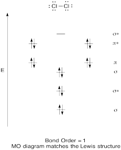
Construct a qualitative molecular orbital diagram for chlorine, Cl2. Compare the bond order to that seen in the Lewis structure (remember that an electron in an antibonding orbital cancels the stabilization due to bonding of an electron in a bonding orbital).
- Answer
Exercise \(\PageIndex{4}\)
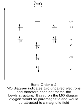
- Construct a qualitative molecular orbital diagram for oxygen, O2.
- Compare the bond order to that seen in the Lewis structure.
- How else does this MO picture of oxygen compare to the Lewis structure? What do the two structures tell you about electron pairing?
- Compounds that have all of their electrons paired are referred to as diamagnetic. Those with unpaired electrons are referred to as paramagnetic. Paramagnetic materials are attracted by a magnetic field, but diamagnetic things are not. How would you expect molecular oxygen to behave?
- Answer
-
Exercise \(\PageIndex{5}\)
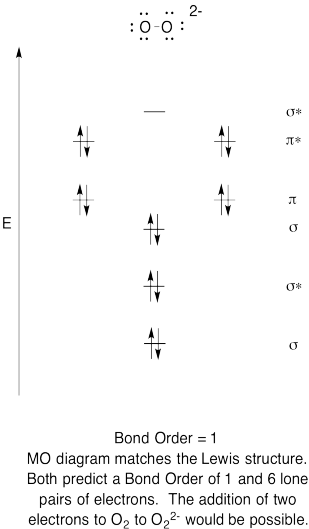
- Construct a qualitative molecular orbital diagram for peroxide anion, O22-.
- Compare the bond order to that seen in the Lewis structure.
- How else does this MO picture of oxygen compare to the Lewis structure? What do the two structures tell you about electron pairing?
- Based on molecular orbital pictures, how easily do you think dioxygen could be reduced to peroxide (through the addition of two electrons)?
- Answer
-
Exercise \(\PageIndex{6}\)
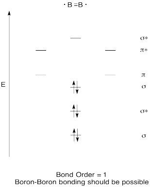
Construct a qualitative molecular orbital diagram for diboron, B2. Do you think boron-boron bonds could form easily, based on this picture?
- Answer
-
Exercise \(\PageIndex{7}\)
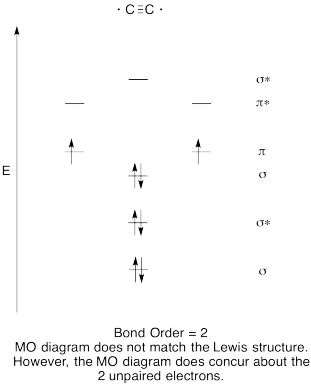
- Construct a qualitative molecular orbital diagram for dicarbon, C2.
- Compare the bond order to that seen in the Lewis structure.
- How else does this MO picture of oxygen compare to the Lewis structure? What do the two structures tell you about electron pairing?
- Answer
-
Exercise \(\PageIndex{8}\)
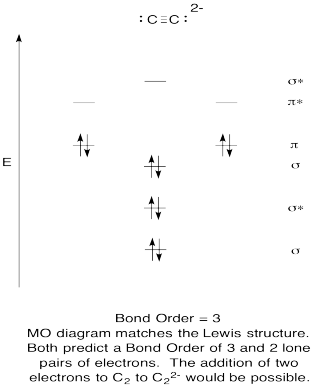
- Construct a qualitative molecular orbital diagram for acetylide anion, C22-.
- Compare the bond order to that seen in the Lewis structure.
- How else does this MO picture of oxygen compare to the Lewis structure? What do the two structures tell you about electron pairing?
- Based on molecular orbital pictures, how easily do you think dicarbon could be reduced to acetylide (through the addition of two electrons)?
- Answer
-
Exercise \(\PageIndex{9}\)
Make drawings and notes to summarize the effect of populating antibonding orbitals.
- Answer
-

Exercise \(\PageIndex{10}\)
Researchers at Johns Hopkins recently reported the formation of Na4Al2 in a pulsed arc discharge (they put a lot of electric current through a sample of sodium and aluminum; Xinxing Zhang, Ivan A. Popov, Katie A. Lundell, Haopeng Wang, Chaonan Mu, Wei Wang, Hansgeorg Schnöckel, Alexander I. Boldyrev, Kit H. Bowen, Angewandte Chemie International Edition, 2018, 57(43), 14060-14064. Copyright 2018, John Wiley & Sons. Used with permission.).
- The compound is ionic. Explain which atoms form the cations, based on periodic trends.
- Therefore, what atoms form the anion?
- The anion is one molecule. What is the charge on this molecule?
- Show how to calculate the total valence electrons in this molecular anion.
- Draw a Lewis structure for this molecular anion.
- Construct a diatomic molecular orbital energy level diagram for this molecule. Label the energy levels (sigma, pi, etc.) and add in the correct number of electrons.
- Show how to calculate the bond order in the molecule.
- Answer
-
a) Na, because Na has a lower ionization potential (and a lower electronegativity) than Al.
b) Al
c) 4-, because there are four Na+
d) total e- = 2 x 3 e- (per Al) + 4 e- (for the negative charge) = 10 e-


g) \(\textrm{bond order} = \frac{( \# bonding \: e^{-} - \# antibonding \: 3^{-})}{2} = \frac{8-2}{2}= 3\)