
A. Introduction to Crystal Field Theory
- Page ID
- 59603

\( \newcommand{\vecs}[1]{\overset { \scriptstyle \rightharpoonup} {\mathbf{#1}} } \)
\( \newcommand{\vecd}[1]{\overset{-\!-\!\rightharpoonup}{\vphantom{a}\smash {#1}}} \)
\( \newcommand{\dsum}{\displaystyle\sum\limits} \)
\( \newcommand{\dint}{\displaystyle\int\limits} \)
\( \newcommand{\dlim}{\displaystyle\lim\limits} \)
\( \newcommand{\id}{\mathrm{id}}\) \( \newcommand{\Span}{\mathrm{span}}\)
( \newcommand{\kernel}{\mathrm{null}\,}\) \( \newcommand{\range}{\mathrm{range}\,}\)
\( \newcommand{\RealPart}{\mathrm{Re}}\) \( \newcommand{\ImaginaryPart}{\mathrm{Im}}\)
\( \newcommand{\Argument}{\mathrm{Arg}}\) \( \newcommand{\norm}[1]{\| #1 \|}\)
\( \newcommand{\inner}[2]{\langle #1, #2 \rangle}\)
\( \newcommand{\Span}{\mathrm{span}}\)
\( \newcommand{\id}{\mathrm{id}}\)
\( \newcommand{\Span}{\mathrm{span}}\)
\( \newcommand{\kernel}{\mathrm{null}\,}\)
\( \newcommand{\range}{\mathrm{range}\,}\)
\( \newcommand{\RealPart}{\mathrm{Re}}\)
\( \newcommand{\ImaginaryPart}{\mathrm{Im}}\)
\( \newcommand{\Argument}{\mathrm{Arg}}\)
\( \newcommand{\norm}[1]{\| #1 \|}\)
\( \newcommand{\inner}[2]{\langle #1, #2 \rangle}\)
\( \newcommand{\Span}{\mathrm{span}}\) \( \newcommand{\AA}{\unicode[.8,0]{x212B}}\)
\( \newcommand{\vectorA}[1]{\vec{#1}} % arrow\)
\( \newcommand{\vectorAt}[1]{\vec{\text{#1}}} % arrow\)
\( \newcommand{\vectorB}[1]{\overset { \scriptstyle \rightharpoonup} {\mathbf{#1}} } \)
\( \newcommand{\vectorC}[1]{\textbf{#1}} \)
\( \newcommand{\vectorD}[1]{\overrightarrow{#1}} \)
\( \newcommand{\vectorDt}[1]{\overrightarrow{\text{#1}}} \)
\( \newcommand{\vectE}[1]{\overset{-\!-\!\rightharpoonup}{\vphantom{a}\smash{\mathbf {#1}}}} \)
\( \newcommand{\vecs}[1]{\overset { \scriptstyle \rightharpoonup} {\mathbf{#1}} } \)
\( \newcommand{\vecd}[1]{\overset{-\!-\!\rightharpoonup}{\vphantom{a}\smash {#1}}} \)
\(\newcommand{\avec}{\mathbf a}\) \(\newcommand{\bvec}{\mathbf b}\) \(\newcommand{\cvec}{\mathbf c}\) \(\newcommand{\dvec}{\mathbf d}\) \(\newcommand{\dtil}{\widetilde{\mathbf d}}\) \(\newcommand{\evec}{\mathbf e}\) \(\newcommand{\fvec}{\mathbf f}\) \(\newcommand{\nvec}{\mathbf n}\) \(\newcommand{\pvec}{\mathbf p}\) \(\newcommand{\qvec}{\mathbf q}\) \(\newcommand{\svec}{\mathbf s}\) \(\newcommand{\tvec}{\mathbf t}\) \(\newcommand{\uvec}{\mathbf u}\) \(\newcommand{\vvec}{\mathbf v}\) \(\newcommand{\wvec}{\mathbf w}\) \(\newcommand{\xvec}{\mathbf x}\) \(\newcommand{\yvec}{\mathbf y}\) \(\newcommand{\zvec}{\mathbf z}\) \(\newcommand{\rvec}{\mathbf r}\) \(\newcommand{\mvec}{\mathbf m}\) \(\newcommand{\zerovec}{\mathbf 0}\) \(\newcommand{\onevec}{\mathbf 1}\) \(\newcommand{\real}{\mathbb R}\) \(\newcommand{\twovec}[2]{\left[\begin{array}{r}#1 \\ #2 \end{array}\right]}\) \(\newcommand{\ctwovec}[2]{\left[\begin{array}{c}#1 \\ #2 \end{array}\right]}\) \(\newcommand{\threevec}[3]{\left[\begin{array}{r}#1 \\ #2 \\ #3 \end{array}\right]}\) \(\newcommand{\cthreevec}[3]{\left[\begin{array}{c}#1 \\ #2 \\ #3 \end{array}\right]}\) \(\newcommand{\fourvec}[4]{\left[\begin{array}{r}#1 \\ #2 \\ #3 \\ #4 \end{array}\right]}\) \(\newcommand{\cfourvec}[4]{\left[\begin{array}{c}#1 \\ #2 \\ #3 \\ #4 \end{array}\right]}\) \(\newcommand{\fivevec}[5]{\left[\begin{array}{r}#1 \\ #2 \\ #3 \\ #4 \\ #5 \\ \end{array}\right]}\) \(\newcommand{\cfivevec}[5]{\left[\begin{array}{c}#1 \\ #2 \\ #3 \\ #4 \\ #5 \\ \end{array}\right]}\) \(\newcommand{\mattwo}[4]{\left[\begin{array}{rr}#1 \amp #2 \\ #3 \amp #4 \\ \end{array}\right]}\) \(\newcommand{\laspan}[1]{\text{Span}\{#1\}}\) \(\newcommand{\bcal}{\cal B}\) \(\newcommand{\ccal}{\cal C}\) \(\newcommand{\scal}{\cal S}\) \(\newcommand{\wcal}{\cal W}\) \(\newcommand{\ecal}{\cal E}\) \(\newcommand{\coords}[2]{\left\{#1\right\}_{#2}}\) \(\newcommand{\gray}[1]{\color{gray}{#1}}\) \(\newcommand{\lgray}[1]{\color{lightgray}{#1}}\) \(\newcommand{\rank}{\operatorname{rank}}\) \(\newcommand{\row}{\text{Row}}\) \(\newcommand{\col}{\text{Col}}\) \(\renewcommand{\row}{\text{Row}}\) \(\newcommand{\nul}{\text{Nul}}\) \(\newcommand{\var}{\text{Var}}\) \(\newcommand{\corr}{\text{corr}}\) \(\newcommand{\len}[1]{\left|#1\right|}\) \(\newcommand{\bbar}{\overline{\bvec}}\) \(\newcommand{\bhat}{\widehat{\bvec}}\) \(\newcommand{\bperp}{\bvec^\perp}\) \(\newcommand{\xhat}{\widehat{\xvec}}\) \(\newcommand{\vhat}{\widehat{\vvec}}\) \(\newcommand{\uhat}{\widehat{\uvec}}\) \(\newcommand{\what}{\widehat{\wvec}}\) \(\newcommand{\Sighat}{\widehat{\Sigma}}\) \(\newcommand{\lt}{<}\) \(\newcommand{\gt}{>}\) \(\newcommand{\amp}{&}\) \(\definecolor{fillinmathshade}{gray}{0.9}\)A note from Dr. Haas: Now we're getting into the grown-up bonding models! First we will learn about Crystal Field Theory (CFT), which is an intermediate theory on your way to the ultimate inorganic bonding theory, Ligand Field Theory (LFT). Please read the content below carefully. The video below may help you understand this reading.
- To understand how crystal field theory explains the electronic structures and colors of metal complexes.
One of the most striking characteristics of transition-metal complexes is the wide range of colors they exhibit. In this section, we describe crystal field theory (CFT), a bonding model that explains many important properties of transition-metal complexes, including their colors, magnetism, structures, stability, and reactivity. The central assumption of CFT is that metal–ligand interactions are purely electrostatic in nature. Even though this assumption is clearly not valid for many complexes, such as those that contain neutral ligands like CO, CFT enables chemists to explain many of the properties of transition-metal complexes with a reasonable degree of accuracy. The Learning Objective of this Module is to understand how crystal field theory explains the electronic structures and colors of metal complexes.
d-Orbital Splittings
CFT focuses on the interaction of the five (n − 1)d orbitals with ligands arranged in a regular array around a transition-metal ion. We will focus on the application of CFT to octahedral complexes, which are by far the most common and the easiest to visualize. Other common structures, such as square planar complexes, can be treated as a distortion of the octahedral model. According to CFT, an octahedral metal complex forms because of the electrostatic interaction of a positively charged metal ion with six negatively charged ligands or with the negative ends of dipoles associated with the six ligands. In addition, the ligands interact with one other electrostatically. As you learned in our discussion of the valence-shell electron-pair repulsion (VSEPR) model, the lowest-energy arrangement of six identical negative charges is an octahedron, which minimizes repulsive interactions between the ligands.
We begin by considering how the energies of the d orbitals of a transition-metal ion are affected by an octahedral arrangement of six negative charges. Recall that the five d orbitals are initially degenerate (have the same energy). If we distribute six negative charges uniformly over the surface of a sphere, the d orbitals remain degenerate, but their energy will be higher due to repulsive electrostatic interactions between the spherical shell of negative charge and electrons in the d orbitals (part (a) in Figure \(\PageIndex{1}\)). Placing the six negative charges at the vertices of an octahedron does not change the average energy of the d orbitals, but it does remove their degeneracy: the five d orbitals split into two groups whose energies depend on their orientations. As shown in part (b) in Figure \(\PageIndex{1}\), the dz2 and dx2−y2 orbitals point directly at the six negative charges located on the x, y, and z axes. Consequently, the energy of an electron in these two orbitals (collectively labeled the eg orbitals) will be greater than it will be for a spherical distribution of negative charge because of increased electrostatic repulsions. In contrast, the other three d orbitals (dxy, dxz, and dyz, collectively called the t2g orbitals) are all oriented at a 45° angle to the coordinate axes, so they point between the six negative charges. The energy of an electron in any of these three orbitals is lower than the energy for a spherical distribution of negative charge.
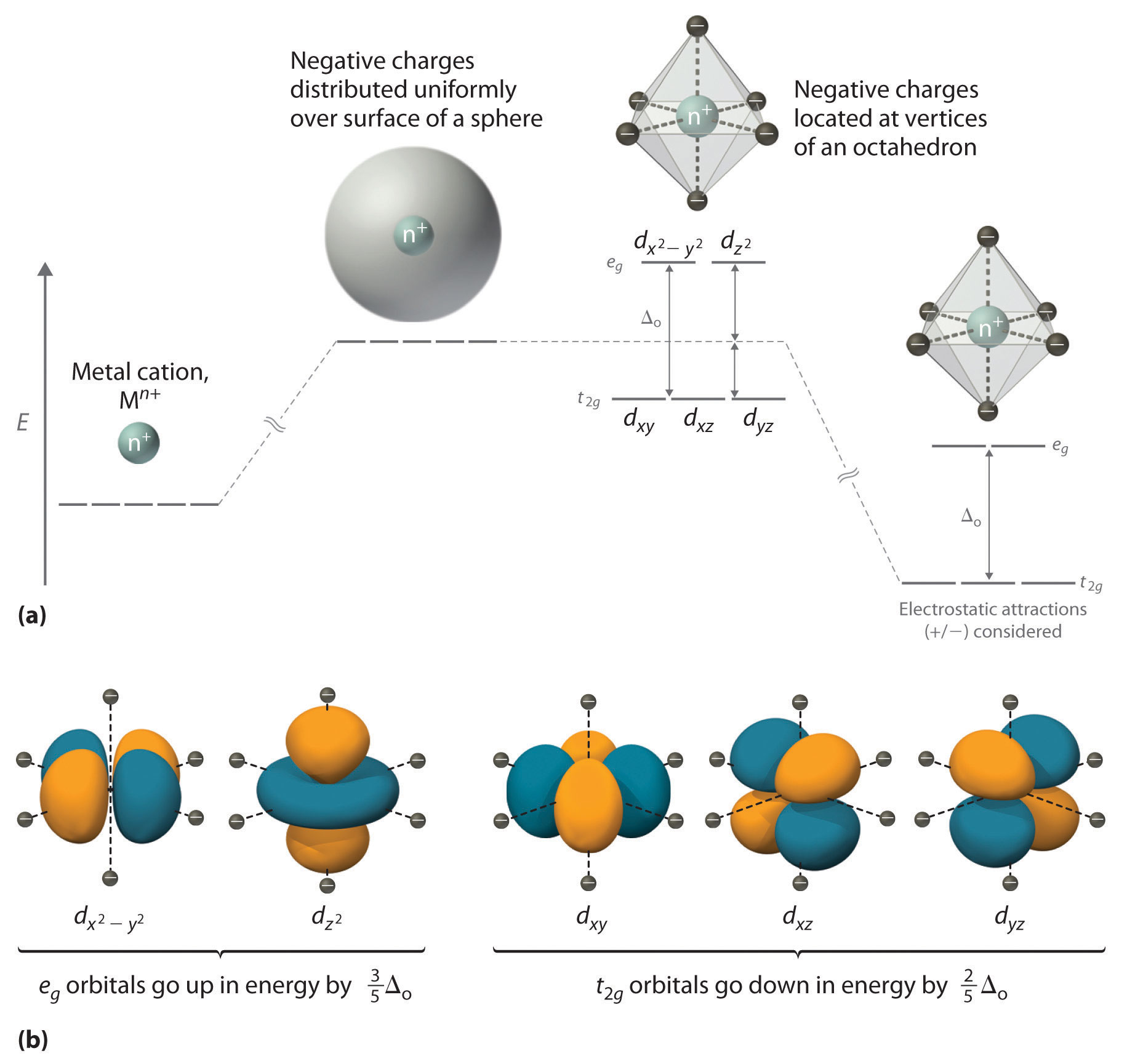
The difference in energy between the two sets of d orbitals is called the crystal field splitting energy (Δo), where the subscript o stands for octahedral. As we shall see, the magnitude of the splitting depends on the charge on the metal ion, the position of the metal in the periodic table, and the nature of the ligands. (Crystal field splitting energy also applies to tetrahedral complexes: Δt.) It is important to note that the splitting of the d orbitals in a crystal field does not change the total energy of the five d orbitals: the two eg orbitals increase in energy by 0.6Δo, whereas the three t2g orbitals decrease in energy by 0.4Δo. Thus the total change in energy is 2(0.6Δo) + 3(−0.4Δo) = 0.
Crystal field splitting does not change the total energy of the d orbitals.
Thus far, we have considered only the effect of repulsive electrostatic interactions between electrons in the d orbitals and the six negatively charged ligands, which increases the total energy of the system and splits the d orbitals. Interactions between the positively charged metal ion and the ligands results in a net stabilization of the system, which decreases the energy of all five d orbitals without affecting their splitting (as shown at the far right in part (a) in Figure \(\PageIndex{1}\)).
Electronic Structures of Octahedral Metal Complexes
We can use the d-orbital energy-level diagram in Figure \(\PageIndex{1}\): to predict electronic structures and some of the properties of transition-metal complexes. We start with the Ti3+ ion, which contains a single d electron, and proceed across the first row of the transition metals by adding a single electron at a time. We place additional electrons in the lowest-energy orbital available, while keeping their spins parallel as required by Hund’s rule. As shown in Figure \(\PageIndex{2}\), for d1–d3 systems—such as [Ti(H2O)6]3+, [V(H2O)6]3+, and [Cr(H2O)6]3+, respectively—the electrons successively occupy the three degenerate t2g orbitals with their spins parallel, giving one, two, and three unpaired electrons, respectively. We can summarize this for the complex [Cr(H2O)6]3+, for example, by saying that the chromium ion has a d3 electron configuration or, more succinctly, Cr3+ is a d3 ion.
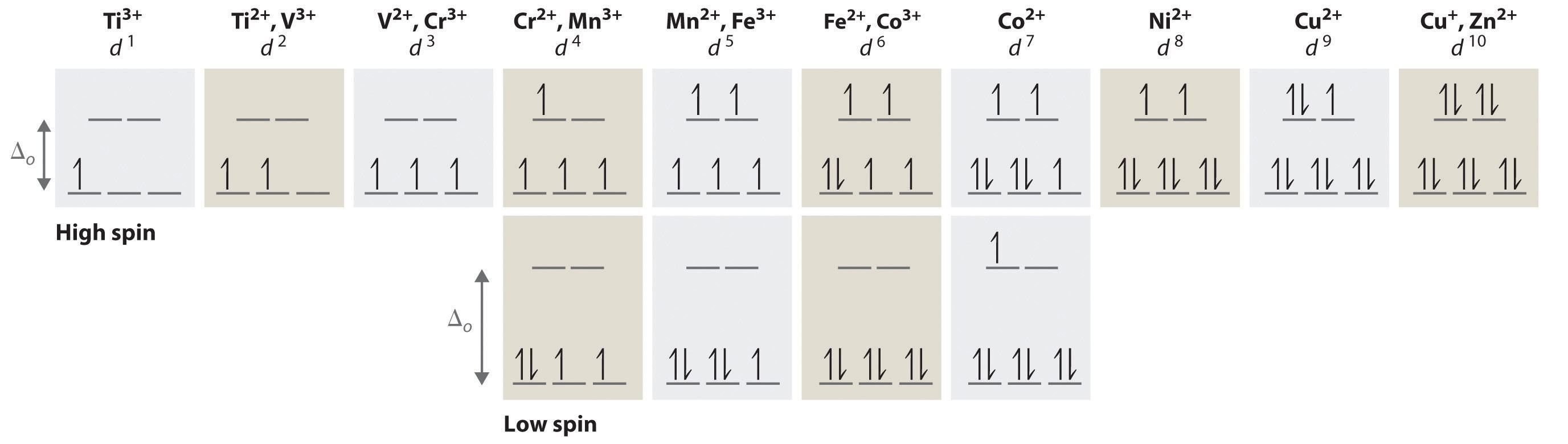
When we reach the d4 configuration, there are two possible choices for the fourth electron: it can occupy either one of the empty eg orbitals or one of the singly occupied t2g orbitals. Recall that placing an electron in an already occupied orbital results in electrostatic repulsions that increase the energy of the system; this increase in energy is called the spin-pairing energy (P). If Δo is less than P, then the lowest-energy arrangement has the fourth electron in one of the empty eg orbitals. Because this arrangement results in four unpaired electrons, it is called a high-spin configuration, and a complex with this electron configuration, such as the [Cr(H2O)6]2+ ion, is called a high-spin complex. Conversely, if Δo is greater than P, then the lowest-energy arrangement has the fourth electron in one of the occupied t2g orbitals. Because this arrangement results in only two unpaired electrons, it is called a low-spin configuration, and a complex with this electron configuration, such as the [Mn(CN)6]3− ion, is called a low-spin complex. Similarly, metal ions with the d5, d6, or d7 electron configurations can be either high spin or low spin, depending on the magnitude of Δo.
In contrast, only one arrangement of d electrons is possible for metal ions with d8–d10 electron configurations. For example, the [Ni(H2O)6]2+ ion is d8 with two unpaired electrons, the [Cu(H2O)6]2+ ion is d9 with one unpaired electron, and the [Zn(H2O)6]2+ ion is d10 with no unpaired electrons.
If Δo is less than the spin-pairing energy, a high-spin configuration results. Conversely, if Δo is greater, a low-spin configuration forms.
Factors That Affect the Magnitude of Δo
The magnitude of Δo dictates whether a complex with four, five, six, or seven d electrons is high spin or low spin, which affects its magnetic properties, structure, and reactivity. Large values of Δo (i.e., Δo > P) yield a low-spin complex, whereas small values of Δo (i.e., Δo < P) produce a high-spin complex. As we noted, the magnitude of Δo depends on three factors: the charge on the metal ion, the principal quantum number of the metal (and thus its location in the periodic table), and the nature of the ligand. Values of Δo for some representative transition-metal complexes are given in Table \(\PageIndex{1}\).
| Octahedral Complexes | Δo (cm−1) | Octahedral Complexes | Δo (cm−1) | Tetrahedral Complexes | Δt (cm−1) |
|---|---|---|---|---|---|
| *Energies obtained by spectroscopic measurements are often given in units of wave numbers (cm−1); the wave number is the reciprocal of the wavelength of the corresponding electromagnetic radiation expressed in centimeters: 1 cm−1 = 11.96 J/mol. | |||||
| [Ti(H2O)6]3+ | 20,300 | [Fe(CN)6]4− | 32,800 | VCl4 | 9010 |
| [V(H2O)6]2+ | 12,600 | [Fe(CN)6]3− | 35,000 | [CoCl4]2− | 3300 |
| [V(H2O)6]3+ | 18,900 | [CoF6]3− | 13,000 | [CoBr4]2− | 2900 |
| [CrCl6]3− | 13,000 | [Co(H2O)6]2+ | 9300 | [CoI4]2− | 2700 |
| [Cr(H2O)6]2+ | 13,900 | [Co(H2O)6]3+ | 27,000 | ||
| [Cr(H2O)6]3+ | 17,400 | [Co(NH3)6]3+ | 22,900 | ||
| [Cr(NH3)6]3+ | 21,500 | [Co(CN)6]3− | 34,800 | ||
| [Cr(CN)6]3− | 26,600 | [Ni(H2O)6]2+ | 8500 | ||
| Cr(CO)6 | 34,150 | [Ni(NH3)6]2+ | 10,800 | ||
| [MnCl6]4− | 7500 | [RhCl6]3− | 20,400 | ||
| [Mn(H2O)6]2+ | 8500 | [Rh(H2O)6]3+ | 27,000 | ||
| [MnCl6]3− | 20,000 | [Rh(NH3)6]3+ | 34,000 | ||
| [Mn(H2O)6]3+ | 21,000 | [Rh(CN)6]3− | 45,500 | ||
| [Fe(H2O)6]2+ | 10,400 | [IrCl6]3− | 25,000 | ||
| [Fe(H2O)6]3+ | 14,300 | [Ir(NH3)6]3+ | 41,000 | ||
Source of data: Duward F. Shriver, Peter W. Atkins, and Cooper H. Langford, Inorganic Chemistry, 2nd ed. (New York: W. H. Freeman and Company, 1994).
Charge on the Metal Ion
Increasing the charge on a metal ion has two effects: the radius of the metal ion decreases, and negatively charged ligands are more strongly attracted to it. Both factors decrease the metal–ligand distance, which in turn causes the negatively charged ligands to interact more strongly with the d orbitals. Consequently, the magnitude of Δo increases as the charge on the metal ion increases. Typically, Δo for a tripositive ion is about 50% greater than for the dipositive ion of the same metal; for example, for [V(H2O)6]2+, Δo = 11,800 cm−1; for [V(H2O)6]3+, Δo = 17,850 cm−1.
Principal Quantum Number of the Metal
For a series of complexes of metals from the same group in the periodic table with the same charge and the same ligands, the magnitude of Δo increases with increasing principal quantum number: Δo (3d) < Δo (4d) < Δo (5d). The data for hexaammine complexes of the trivalent Group 9 metals illustrate this point:
The increase in Δo with increasing principal quantum number is due to the larger radius of valence orbitals down a column. In addition, repulsive ligand–ligand interactions are most important for smaller metal ions. Relatively speaking, this results in shorter M–L distances and stronger d orbital–ligand interactions.
The Nature of the Ligands
Experimentally, it is found that the Δo observed for a series of complexes of the same metal ion depends strongly on the nature of the ligands. For a series of chemically similar ligands, the magnitude of Δo decreases as the size of the donor atom increases. For example, Δo values for halide complexes generally decrease in the order F− > Cl− > Br− > I− because smaller, more localized charges, such as we see for F−, interact more strongly with the d orbitals of the metal ion. In addition, a small neutral ligand with a highly localized lone pair, such as NH3, results in significantly larger Δo values than might be expected. Because the lone pair points directly at the metal ion, the electron density along the M–L axis is greater than for a spherical anion such as F−. The experimentally observed order of the crystal field splitting energies produced by different ligands is called the spectrochemical series, shown here in order of decreasing Δo:
The values of Δo listed in Table \(\PageIndex{1}\) illustrate the effects of the charge on the metal ion, the principal quantum number of the metal, and the nature of the ligand.
The largest Δos are found in complexes of metal ions from the third row of the transition metals with charges of at least +3 and ligands with localized lone pairs of electrons.
Colors of Transition-Metal Complexes
The striking colors exhibited by transition-metal complexes are caused by excitation of an electron from a lower-energy d orbital to a higher-energy d orbital, which is called a d–d transition (Figure \(\PageIndex{3}\)). For a photon to effect such a transition, its energy must be equal to the difference in energy between the two d orbitals, which depends on the magnitude of Δo.
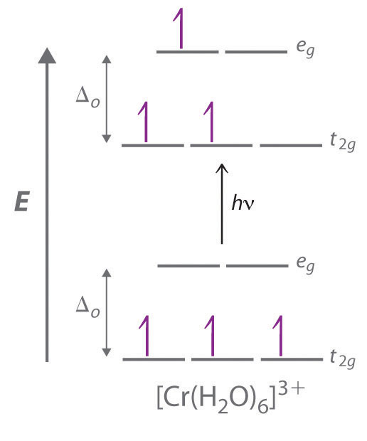
Recall that the color we observe when we look at an object or a compound is due to light that is transmitted or reflected, not light that is absorbed, and that reflected or transmitted light is complementary in color to the light that is absorbed. Thus a green compound absorbs light in the red portion of the visible spectrum and vice versa, as indicated by the color wheel. Because the energy of a photon of light is inversely proportional to its wavelength, the color of a complex depends on the magnitude of Δo, which depends on the structure of the complex. For example, the complex [Cr(NH3)6]3+ has strong-field ligands and a relatively large Δo. Consequently, it absorbs relatively high-energy photons, corresponding to blue-violet light, which gives it a yellow color. A related complex with weak-field ligands, the [Cr(H2O)6]3+ ion, absorbs lower-energy photons corresponding to the yellow-green portion of the visible spectrum, giving it a deep violet color.
We can now understand why emeralds and rubies have such different colors, even though both contain Cr3+ in an octahedral environment provided by six oxide ions. Although the chemical identity of the six ligands is the same in both cases, the Cr–O distances are different because the compositions of the host lattices are different (Al2O3 in rubies and Be3Al2Si6O18 in emeralds). In ruby, the Cr–O distances are relatively short because of the constraints of the host lattice, which increases the d orbital–ligand interactions and makes Δo relatively large. Consequently, rubies absorb green light and the transmitted or reflected light is red, which gives the gem its characteristic color. In emerald, the Cr–O distances are longer due to relatively large [Si6O18]12− silicate rings; this results in decreased d orbital–ligand interactions and a smaller Δo. Consequently, emeralds absorb light of a longer wavelength (red), which gives the gem its characteristic green color. It is clear that the environment of the transition-metal ion, which is determined by the host lattice, dramatically affects the spectroscopic properties of a metal ion.
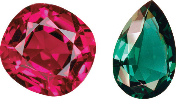
Gem-quality crystals of ruby and emerald. The colors of both minerals are due to the presence of small amounts of Cr3+ impurities in octahedral sites in an otherwise colorless metal oxide lattice.