
6.12: Colors of Coordination Complexes
- Page ID
- 445363
\( \newcommand{\vecs}[1]{\overset { \scriptstyle \rightharpoonup} {\mathbf{#1}} } \)
\( \newcommand{\vecd}[1]{\overset{-\!-\!\rightharpoonup}{\vphantom{a}\smash {#1}}} \)
\( \newcommand{\id}{\mathrm{id}}\) \( \newcommand{\Span}{\mathrm{span}}\)
( \newcommand{\kernel}{\mathrm{null}\,}\) \( \newcommand{\range}{\mathrm{range}\,}\)
\( \newcommand{\RealPart}{\mathrm{Re}}\) \( \newcommand{\ImaginaryPart}{\mathrm{Im}}\)
\( \newcommand{\Argument}{\mathrm{Arg}}\) \( \newcommand{\norm}[1]{\| #1 \|}\)
\( \newcommand{\inner}[2]{\langle #1, #2 \rangle}\)
\( \newcommand{\Span}{\mathrm{span}}\)
\( \newcommand{\id}{\mathrm{id}}\)
\( \newcommand{\Span}{\mathrm{span}}\)
\( \newcommand{\kernel}{\mathrm{null}\,}\)
\( \newcommand{\range}{\mathrm{range}\,}\)
\( \newcommand{\RealPart}{\mathrm{Re}}\)
\( \newcommand{\ImaginaryPart}{\mathrm{Im}}\)
\( \newcommand{\Argument}{\mathrm{Arg}}\)
\( \newcommand{\norm}[1]{\| #1 \|}\)
\( \newcommand{\inner}[2]{\langle #1, #2 \rangle}\)
\( \newcommand{\Span}{\mathrm{span}}\) \( \newcommand{\AA}{\unicode[.8,0]{x212B}}\)
\( \newcommand{\vectorA}[1]{\vec{#1}} % arrow\)
\( \newcommand{\vectorAt}[1]{\vec{\text{#1}}} % arrow\)
\( \newcommand{\vectorB}[1]{\overset { \scriptstyle \rightharpoonup} {\mathbf{#1}} } \)
\( \newcommand{\vectorC}[1]{\textbf{#1}} \)
\( \newcommand{\vectorD}[1]{\overrightarrow{#1}} \)
\( \newcommand{\vectorDt}[1]{\overrightarrow{\text{#1}}} \)
\( \newcommand{\vectE}[1]{\overset{-\!-\!\rightharpoonup}{\vphantom{a}\smash{\mathbf {#1}}}} \)
\( \newcommand{\vecs}[1]{\overset { \scriptstyle \rightharpoonup} {\mathbf{#1}} } \)
\( \newcommand{\vecd}[1]{\overset{-\!-\!\rightharpoonup}{\vphantom{a}\smash {#1}}} \)
\(\newcommand{\avec}{\mathbf a}\) \(\newcommand{\bvec}{\mathbf b}\) \(\newcommand{\cvec}{\mathbf c}\) \(\newcommand{\dvec}{\mathbf d}\) \(\newcommand{\dtil}{\widetilde{\mathbf d}}\) \(\newcommand{\evec}{\mathbf e}\) \(\newcommand{\fvec}{\mathbf f}\) \(\newcommand{\nvec}{\mathbf n}\) \(\newcommand{\pvec}{\mathbf p}\) \(\newcommand{\qvec}{\mathbf q}\) \(\newcommand{\svec}{\mathbf s}\) \(\newcommand{\tvec}{\mathbf t}\) \(\newcommand{\uvec}{\mathbf u}\) \(\newcommand{\vvec}{\mathbf v}\) \(\newcommand{\wvec}{\mathbf w}\) \(\newcommand{\xvec}{\mathbf x}\) \(\newcommand{\yvec}{\mathbf y}\) \(\newcommand{\zvec}{\mathbf z}\) \(\newcommand{\rvec}{\mathbf r}\) \(\newcommand{\mvec}{\mathbf m}\) \(\newcommand{\zerovec}{\mathbf 0}\) \(\newcommand{\onevec}{\mathbf 1}\) \(\newcommand{\real}{\mathbb R}\) \(\newcommand{\twovec}[2]{\left[\begin{array}{r}#1 \\ #2 \end{array}\right]}\) \(\newcommand{\ctwovec}[2]{\left[\begin{array}{c}#1 \\ #2 \end{array}\right]}\) \(\newcommand{\threevec}[3]{\left[\begin{array}{r}#1 \\ #2 \\ #3 \end{array}\right]}\) \(\newcommand{\cthreevec}[3]{\left[\begin{array}{c}#1 \\ #2 \\ #3 \end{array}\right]}\) \(\newcommand{\fourvec}[4]{\left[\begin{array}{r}#1 \\ #2 \\ #3 \\ #4 \end{array}\right]}\) \(\newcommand{\cfourvec}[4]{\left[\begin{array}{c}#1 \\ #2 \\ #3 \\ #4 \end{array}\right]}\) \(\newcommand{\fivevec}[5]{\left[\begin{array}{r}#1 \\ #2 \\ #3 \\ #4 \\ #5 \\ \end{array}\right]}\) \(\newcommand{\cfivevec}[5]{\left[\begin{array}{c}#1 \\ #2 \\ #3 \\ #4 \\ #5 \\ \end{array}\right]}\) \(\newcommand{\mattwo}[4]{\left[\begin{array}{rr}#1 \amp #2 \\ #3 \amp #4 \\ \end{array}\right]}\) \(\newcommand{\laspan}[1]{\text{Span}\{#1\}}\) \(\newcommand{\bcal}{\cal B}\) \(\newcommand{\ccal}{\cal C}\) \(\newcommand{\scal}{\cal S}\) \(\newcommand{\wcal}{\cal W}\) \(\newcommand{\ecal}{\cal E}\) \(\newcommand{\coords}[2]{\left\{#1\right\}_{#2}}\) \(\newcommand{\gray}[1]{\color{gray}{#1}}\) \(\newcommand{\lgray}[1]{\color{lightgray}{#1}}\) \(\newcommand{\rank}{\operatorname{rank}}\) \(\newcommand{\row}{\text{Row}}\) \(\newcommand{\col}{\text{Col}}\) \(\renewcommand{\row}{\text{Row}}\) \(\newcommand{\nul}{\text{Nul}}\) \(\newcommand{\var}{\text{Var}}\) \(\newcommand{\corr}{\text{corr}}\) \(\newcommand{\len}[1]{\left|#1\right|}\) \(\newcommand{\bbar}{\overline{\bvec}}\) \(\newcommand{\bhat}{\widehat{\bvec}}\) \(\newcommand{\bperp}{\bvec^\perp}\) \(\newcommand{\xhat}{\widehat{\xvec}}\) \(\newcommand{\vhat}{\widehat{\vvec}}\) \(\newcommand{\uhat}{\widehat{\uvec}}\) \(\newcommand{\what}{\widehat{\wvec}}\) \(\newcommand{\Sighat}{\widehat{\Sigma}}\) \(\newcommand{\lt}{<}\) \(\newcommand{\gt}{>}\) \(\newcommand{\amp}{&}\) \(\definecolor{fillinmathshade}{gray}{0.9}\)The color for a coordination complex can be predicted using the Crystal Field Theory (CFT). The tendency for coordination complexes to display such a wide array of colors is merely coincidental; the d-orbital splitting in coordination complexes results in a gap (\(\Delta\)) that happens to be just the right magnitude to absorb visible light. Because metal complexes can absorb visible light, they display an array of colors. Not only is the color attractive to the eye, it is an indication of the chemical and physical properties of the metal complex. The color (like the magnitude of \(\Delta\)) depends on the identity of the metal ion, the coordination geometry, and the ligand identity. Chemists don't just "look" at color, though - we measure it using electronic absorption spectroscopy. This is usually done in a lab using a UV-visible spectrophotometer.
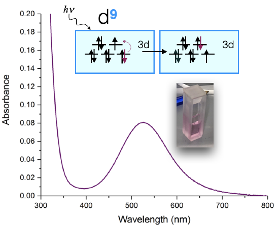
An example of such a measurement is shown below in Figure \(\PageIndex{1}\) for a Cu(II) complex. The sample appears a pink color to the eye, and when it is measured using a UV-visible spectrometer, it is shown to absorb visible light at approximately 530 nm. The absorption spectrum can indicate the oxidation state of Cu, the ligands bound to the Cu(II) ion, and the coordination geometry. The color of the solution in Figure \(\PageIndex{1}\) is a shade of pink.
The Electromagnetic Spectrum
The electromagnetic spectrum (EM) spectrum is made up of photons of different wavelengths. Photons, unique in displaying the properties of both waves and particles, create visible light and colors in a small portion of the EM spectrum. This visible light portion has wavelengths in approximately the 400-750 nanometer range (a nanometer, “nm,” is 10-9 meters). Each specific wavelength corresponds to a different color (Figure \(\PageIndex{2}\)), and when all the wavelengths are present, it appears as white light.

The wavelength and frequency of a wave are inversely proportional: as one increases, the other decreases; this is a consequence of all light traveling at the same speed.
\[\lambda \propto \nu^{-1} \nonumber \]
Because of this relationship, blue light has a much higher frequency and more energy than red light.
Perceiving Color
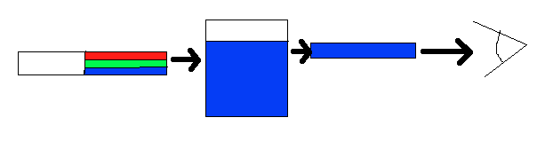
Color is perceived in two ways, through additive mixing, where different colors are made by combining different colors of light, and through subtractive mixing, where different wavelengths of light are taken out so that the light is no longer pure white. For colors of coordination complexes, subtractive mixing is considered. As shown in Figure \(\PageIndex{3}\), the idea behind subtractive mixing is that white light (which is made from all the colors mixed together) interacts with an object. The object absorbs some of the light, and then reflects or transmits (or both, depending on the object) the rest of the light, which contacts the eye. The object is perceived as whichever color is not absorbed. In Figure \(\PageIndex{3}\), white light (simplified as green, red, and blue bands) is shone through a solution. The solution absorbs the red and green wavelengths; however, the blue light is reflected and passes through, so the solution appears blue. This procedure takes place whenever an object displays visible color. If none of the light is absorbed, and all is reflected back off, the object appears white; if all of the light is absorbed, and there is none left to reflect or transmit through, the object appears black.
If white light (ordinary sunlight, for example) passes through copper(II) sulfate solution, some wavelengths in the light are absorbed by the solution. Copper(II) ions in solution absorb light in the red region of the spectrum. The light which passes through the solution and out the other side will have all the colors in it except for the red. We see this mixture of wavelengths as pale blue (cyan). The diagram gives an impression of what happens if you pass white light through copper(II) sulfate solution.
Working out what color you will see is not easy if you try to do it by imagining "mixing up" the remaining colors. You wouldn't have thought that all the other colors apart from some red would look cyan, for example. Sometimes what you actually see is quite unexpected. Mixing different wavelengths of light doesn't give you the same result as mixing paints or other pigments. You can, however, sometimes get some estimate of the color you would see using the idea of complementary colors.
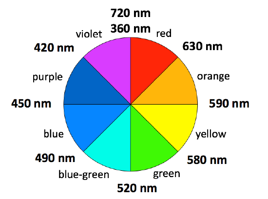
The absorption spectrum shown above in Figure \(\PageIndex{1}\) is a simple case in which only one absorption band is observed in the visible region of the spectrum. In a simple case like this, the color of a complex can be predicted using a color wheel. When a solution or object absorbs a certain wavelength, we see the complementary color, or the color opposite to the absorbed wavelength on the color wheel in Figure \(\PageIndex{4}\). In the case of the Cu(II) complex spectrum shown in Figure \(\PageIndex{1}\), the color of the light absorbed at 530 nm is green, and the predicted color observed is pink. Table \(\PageIndex{1}\) lists the approximate colors of absorption corresponding to wavelengths of light absorbed and gives similar information to that deduced from Figure \(\PageIndex{4}\).

| \(\lambda\) absorbed | E (cm\(^{-1}\)) | E (eV) | Approximate color absorbed | Predicted color observed (by eye) |
|---|---|---|---|---|
| \(> 700\) nm | \(< 14,000 \frac{1}{\text{cm}}\) | \( < 1.77\) eV | Infrared | not observable |
| \(\approx 700-635\) nm | \(\approx 14,300- 16,000\frac{1}{\text{cm}}\) | \( \approx 1.77-1.95\) eV | Red | Green |
| \(\approx 635-590\) nm | \(\approx 15,700- 16,900 \frac{1}{\text{cm}}\) | \( \approx 1.95-2.10\) eV | Orange | Blue |
| \(\approx 590-560\) nm | \(\approx 16,900-17,900 \frac{1}{\text{cm}}\) | \( \approx 2.10-2.21\) eV | Yellow | Violet |
| \(\approx 560-520\) nm | \(\approx 17,900- 19,200 \frac{1}{\text{cm}}\) | \( \approx 2.21-2.38\) eV | Green | Red |
| \(\approx 520-490\) nm | \(\approx 19,200- 20,400 \frac{1}{\text{cm}}\) | \( \approx 2.38-2.53\) eV | Cyan | Red-Orange |
| \(\approx 490-450\) nm | \(\approx 20,400- 22,200 \frac{1}{\text{cm}}\) | \( \approx 2.53-2.76\) eV | Blue | Orange |
| \(400-450\) nm | \(\approx 22,200- 25,000 \frac{1}{\text{cm}}\) | \( \approx 2.76-3.10\) eV | Violet | Yellow |
| <400 nm | \(> 25,000 \frac{1}{\text{cm}}\) | \( > 3.10\) eV | Ultraviolet (UV) | not observable |
Colors of Coordination Complexes: Crystal Field Splitting
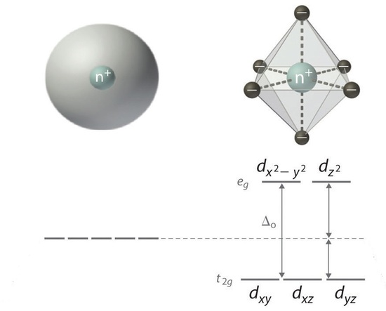
When ligands attach to a transition metal to form a coordination complex, electrons in the d orbital split into high energy and low energy orbitals. The difference in energy of the two levels is denoted as ∆, and it is a characteristic a property both of the metal and the ligands. This is illustrated in Figure \(\PageIndex{5}\); the "o" subscript on the ∆ indicates that the complex has octahedral geometry.
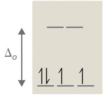
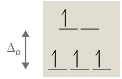
If ∆o is large, and much energy is required to promote electrons into the high energy orbitals, the electrons will instead pair in the lower energy orbitals, resulting in a "low spin" complex (Figure \(\PageIndex{6}\)); however, if ∆o is small, and it takes little energy to occupy the higher orbitals, the electrons will do so, and remain unpaired (until there are more than five electrons), resulting in a “high spin” complex. Different ligands are associated with either high or low spin —a "strong field" ligand results in a large ∆o and a low spin configuration, while a "weak field" ligand results in a small ∆o and a high spin configuration. For more details, see the Crystal Field Theory (CFT) page.
A photon equal to the energy difference ∆o can be absorbed, promoting an electron to the higher energy level. As certain wavelengths are absorbed in this process, subtractive color mixing occurs and the coordination complex solution becomes colored. If the ions have a noble gas configuration, and have no unpaired electrons, the solutions appear colorless; in reality, they still have a measured energy and absorb certain wavelengths of light, but these wavelengths are not in the visible portion of the EM spectrum and no color is perceived by the eye.
In general, a larger \(∆\) indicates that higher energy photons are absorbed, and the solution appears further to the left on the EM spectrum shown in Figure \(\PageIndex{2}\). This relationship is described in the equation
\[\Delta=\frac{hc}{\lambda} \nonumber \]
where
- \(h\) is Planck's constant (\(\ =6.626 \times 10^{-34} Js \))
- \(c\) is the speed of light (\(\ = 2.998 \times 10^8 \frac{m}{s} \))
- \(\lambda \) is the wavelength of light absorbed in units of \(\text{m}\)
Relating the Colors of Coordination Complexes to the Spectrochemical Series
According to the Crystal Field Theory, ligands that induce smaller CFSE (\(\Delta\)) values are considered "weak field" and will absorb lower-energy light with longer \(\lambda\) values (ie a "red shift"). Ligands that induce larger CFSE values are considered "strong field" and will absorb higher-energy light with shorter \(\lambda\) values (ie a "blue shift"). Thus, the energy difference, \(\Delta\), determines the color of the coordination complex.
The spectrochemical series, introduced previously, ranks ligands from weak field/high spin ot strong field/ low spin. It can be used to compare the approximate \(\Delta\) values of ligands and to predict which wavelengths will be absorbed a complex, and thereby, what color it will appear.
\[ \underset{\textrm{weak-field ligands}}{I^- < Br^- < Cl^-} < \underline{S}CN^- < CH_3COO^- < F^- < OH^- < ox^{2-} < \underset{\textrm{intermediate-field ligands}}{ONO^- < H_2O < SC\underline{N}^-} < EDTA^{4-} <NH_3 < en < NO_2^- < \underset{\textrm{strong-field ligands}}{ CN^- \approx CO} \nonumber\]
The greater the CFSE, the more energy that is needed to promote an electron from the lower group of orbitals to the higher ones. In terms of the color of the light absorbed, greater energy corresponds to shorter wavelengths. That means that as the splitting increases, the light absorbed will tend to shift away from the red end of the spectrum towards orange, yellow and so on. There is a fairly clear-cut case in copper(II) chemistry. If you add an excess of ammonia solution to hexaaquacopper(II) ions in solution, the pale blue (cyan) color is replaced by a dark inky blue as some of the water molecules in the complex ion are replaced by ammonia.

The first complex must be absorbing red light in order to give the complementary color cyan. The second one must be absorbing in the yellow region in order to give the complementary color dark blue. Yellow light has a higher energy than red light. You need that higher energy because ammonia causes more splitting of the d orbitals than water does.
Other Factors
The oxidation state of the metal
As the oxidation state of the metal increases, so also does the amount of splitting of the d orbitals. Changes of oxidation state therefore change the color of the light absorbed, and so the color of the light you see. Taking another example from chromium chemistry involving only a change of oxidation state (from +2 to +3):
The 2+ ion is almost the same color as the hexaaquacopper(II) ion, and the 3+ ion is the hard-to-describe violet-blue-grey color.
The coordination of the Ion
Splitting is greater if the ion is octahedral than if it is tetrahedral, and therefore the color will change with a change of co-ordination. The problem is that an ion will normally only change co-ordination if you change the ligand - and changing the ligand will change the color as well. Hence, you cannot isolate out the effect of the co-ordination change. For example, a commonly quoted case comes from cobalt(II) chemistry, with the ions [Co(H2O)6]2+ and [CoCl4]2-.
The difference in the colors is going to be a combination of the effect of the change of ligand, and the change of the number of ligands.
If a solution with a dissolved octahedral complex appears yellow to the eye, what wavelength of light does it absorb? Is this complex expected to be low spin or high spin?
Solution
A solution that looks yellow absorbs light that is violet, which is roughly 410 nm from the color wheel. Since it absorbs high energy, the electrons must be raised to a higher level, and \(\Delta_o\) is high, so the complex is likely to be low spin.
An octahedral metal complex absorbs light with wavelength 535 nm. What is the crystal field splitting \(\Delta_o\) for the complex? What color is it to the eye?
Solution
To solve this question, we need to use the equation
\[\Delta_o =\dfrac{hc}{\lambda} \nonumber \]
with
- \(h\) is Planck’s constant and is \(6.625 \times 10^{-34} J \cdot s\) and
- \(c\) is the speed of light and is \(2.998 \times 10^8\, m/s\).
It is also important to remember that 1 nm is equal to \(1 \times 10^{-9}\) meters. With all this information, the final equation looks like this:
\[\Delta_o =\dfrac{(6.625 \times 10^{-34}\, J \cdot s)(2.998 \times 10^8\, m/s)}{(535nm) \left(\dfrac{1\,m}{1 \times 10^9\, nm}\right)}= 3.712 \,J/molecule \nonumber \]
It is not necessary to use any equations to solve the second part of the problem. Light that is 535 nm is green, and because green light is absorbed, the complex appears red (refer to Figures \(\PageIndex{1}\) and \(\PageIndex{6}\) for this information).
Note: the fact that the complex is octahedral makes no impact when solving this problem. Although the splitting is different for complexes of different structures, the mechanics of solving the problem are identical.
There are two solutions, one orange and one blue. Both solutions are known to be made up of a cobalt complex; however, one has chloride ions as ligands, while the other has ammonia ligands. Which solution is expected to be orange?
Solution
In order to solve this problem, it is necessary to know the relative strengths of the ligands involved. A sample ligand strength list is given here, but see Crystal Field Splitting for a more complete list:
CN- > en > NH3 > H2O > F- >SCN- > Cl-
From this information, it is clear that NH3 is a stronger ligand than Cl-, which means that the complex involving NH3 has a greater ∆, and the complex will be low spin. Because of the larger ∆, the electrons absorb higher energy photons, and the solution will have the appearance of a lower energy color. Since orange light is less energetic than blue light, the NH3 containing solution is predicted to be orange
A tetrahedral complex absorbs at 545 nm. What is the respective octahedral crystal field splitting (\(\Delta_o\))? What is the color of the complex?
Solution
\[\begin{align*} \Delta_t &= \dfrac{hc}{\lambda}\\[4pt] &= \dfrac{ (6.626 \times 10^{-34} J \cdot s)(3 \times 10^8 m/s)}{545 \times 10^{-9} m} \\[4pt] &=3.65 \times 10^{-19}\; J \end{align*} \]
However, the tetrahedral splitting (\(\Delta_t\)) is ~4/9 that of the octahedral splitting (\(\Delta_o\)).
\[\begin{align*} \Delta_t &= 0.44\Delta_o \\[4pt] \Delta_o &= \dfrac{\Delta_t}{0.44} \\[4pt] &= \dfrac{3.65 \times 10^{-19} J}{0.44} \\[4pt] &= 8.30 \times 10^{-18}J \end{align*} \]
This is the energy needed to promote one electron in one complex. Often the crystal field splitting is given per mole, which requires this number to be multiplied by Avogadro's Number (\(6.022 \times 10^{23}\)).
This complex appears red, since it absorbs in the complementary green color (determined via the color wheel).
Problems
What color will a complex be that absorbs light that is 600 nm be?
- Answer
-
Blue. The color absorbed is orange.
What color will a complex an octahedral complex appear if it has a \(\Delta_o\) of \(3.75 \times 10^{-19}\, J\)?
- Answer
-
It is red. Using Δ=hc/λ, h=6.626*10-34J*s, c=2.998*108m/s, wavelength would equal 530 nm. So green is absorbed, and the complementary color of green is red, so red is the color of the complex.
Would you expect a violet solution to be high spin or low spin? What about a red solution?
- Answer
-
It would be high spin. The complementary color of violet is yellow, which has a wavelength of 570 nm. For a red solution, the complementary color absorbed is green, with a wavelength of 530 nm, so it would be considered low spin.
There are two solutions, one which is yellow and another which is violet. The solutions are [Co(H2O)6]3+and [Co(CN-)6]3-. What are the colors of each solution?
- Answer
-
[Co(H2O)6]3+ is violet and [Co(CN-)6]3- is yellow. Looking at the spectrochemical series, H2O is a weak field ligand, so it absorbs colors of long wavelengths—in this case, the longer wavelength is yellow, so the color reflected is violet. CN- is a strong field ligand, so it absorbs colors of shorter wavelengths-in this case, the shorter wavelength is violet, so the color reflected is yellow.
Contributors and Attributions
- Deyu Wang (UCD)
-
References
- Cox, P. A. Instant Notes Inorganic Chemistry. Second ed. Grand Rapids: Garland, Incorporated, 2004.
- Nassau, Kurt. The Physics and Chemistry of Color : The Fifteen Causes of Color. Second ed. New York: Wiley-Interscience, 2001.
- Petrucci, Ralph H., William S. Harwood, and Geoff E. Herring. General Chemistry : Principles and Modern Applications. Ninth ed. Upper Saddle River: Prentice Hall PTR, 2006.
- Petrucci, Ralph H., Carey Bissonnette, F. Geoffrey Herring, Jeffrey D. Madura. General Chemistry: Principles and Modern Applications. Tenth Ed. Upper Saddle River: Pearson Education, Inc. 2011.