5.2: Auger Electron Spectroscopy
- Page ID
- 25382
\( \newcommand{\vecs}[1]{\overset { \scriptstyle \rightharpoonup} {\mathbf{#1}} } \)
\( \newcommand{\vecd}[1]{\overset{-\!-\!\rightharpoonup}{\vphantom{a}\smash {#1}}} \)
\( \newcommand{\id}{\mathrm{id}}\) \( \newcommand{\Span}{\mathrm{span}}\)
( \newcommand{\kernel}{\mathrm{null}\,}\) \( \newcommand{\range}{\mathrm{range}\,}\)
\( \newcommand{\RealPart}{\mathrm{Re}}\) \( \newcommand{\ImaginaryPart}{\mathrm{Im}}\)
\( \newcommand{\Argument}{\mathrm{Arg}}\) \( \newcommand{\norm}[1]{\| #1 \|}\)
\( \newcommand{\inner}[2]{\langle #1, #2 \rangle}\)
\( \newcommand{\Span}{\mathrm{span}}\)
\( \newcommand{\id}{\mathrm{id}}\)
\( \newcommand{\Span}{\mathrm{span}}\)
\( \newcommand{\kernel}{\mathrm{null}\,}\)
\( \newcommand{\range}{\mathrm{range}\,}\)
\( \newcommand{\RealPart}{\mathrm{Re}}\)
\( \newcommand{\ImaginaryPart}{\mathrm{Im}}\)
\( \newcommand{\Argument}{\mathrm{Arg}}\)
\( \newcommand{\norm}[1]{\| #1 \|}\)
\( \newcommand{\inner}[2]{\langle #1, #2 \rangle}\)
\( \newcommand{\Span}{\mathrm{span}}\) \( \newcommand{\AA}{\unicode[.8,0]{x212B}}\)
\( \newcommand{\vectorA}[1]{\vec{#1}} % arrow\)
\( \newcommand{\vectorAt}[1]{\vec{\text{#1}}} % arrow\)
\( \newcommand{\vectorB}[1]{\overset { \scriptstyle \rightharpoonup} {\mathbf{#1}} } \)
\( \newcommand{\vectorC}[1]{\textbf{#1}} \)
\( \newcommand{\vectorD}[1]{\overrightarrow{#1}} \)
\( \newcommand{\vectorDt}[1]{\overrightarrow{\text{#1}}} \)
\( \newcommand{\vectE}[1]{\overset{-\!-\!\rightharpoonup}{\vphantom{a}\smash{\mathbf {#1}}}} \)
\( \newcommand{\vecs}[1]{\overset { \scriptstyle \rightharpoonup} {\mathbf{#1}} } \)
\( \newcommand{\vecd}[1]{\overset{-\!-\!\rightharpoonup}{\vphantom{a}\smash {#1}}} \)
\(\newcommand{\avec}{\mathbf a}\) \(\newcommand{\bvec}{\mathbf b}\) \(\newcommand{\cvec}{\mathbf c}\) \(\newcommand{\dvec}{\mathbf d}\) \(\newcommand{\dtil}{\widetilde{\mathbf d}}\) \(\newcommand{\evec}{\mathbf e}\) \(\newcommand{\fvec}{\mathbf f}\) \(\newcommand{\nvec}{\mathbf n}\) \(\newcommand{\pvec}{\mathbf p}\) \(\newcommand{\qvec}{\mathbf q}\) \(\newcommand{\svec}{\mathbf s}\) \(\newcommand{\tvec}{\mathbf t}\) \(\newcommand{\uvec}{\mathbf u}\) \(\newcommand{\vvec}{\mathbf v}\) \(\newcommand{\wvec}{\mathbf w}\) \(\newcommand{\xvec}{\mathbf x}\) \(\newcommand{\yvec}{\mathbf y}\) \(\newcommand{\zvec}{\mathbf z}\) \(\newcommand{\rvec}{\mathbf r}\) \(\newcommand{\mvec}{\mathbf m}\) \(\newcommand{\zerovec}{\mathbf 0}\) \(\newcommand{\onevec}{\mathbf 1}\) \(\newcommand{\real}{\mathbb R}\) \(\newcommand{\twovec}[2]{\left[\begin{array}{r}#1 \\ #2 \end{array}\right]}\) \(\newcommand{\ctwovec}[2]{\left[\begin{array}{c}#1 \\ #2 \end{array}\right]}\) \(\newcommand{\threevec}[3]{\left[\begin{array}{r}#1 \\ #2 \\ #3 \end{array}\right]}\) \(\newcommand{\cthreevec}[3]{\left[\begin{array}{c}#1 \\ #2 \\ #3 \end{array}\right]}\) \(\newcommand{\fourvec}[4]{\left[\begin{array}{r}#1 \\ #2 \\ #3 \\ #4 \end{array}\right]}\) \(\newcommand{\cfourvec}[4]{\left[\begin{array}{c}#1 \\ #2 \\ #3 \\ #4 \end{array}\right]}\) \(\newcommand{\fivevec}[5]{\left[\begin{array}{r}#1 \\ #2 \\ #3 \\ #4 \\ #5 \\ \end{array}\right]}\) \(\newcommand{\cfivevec}[5]{\left[\begin{array}{c}#1 \\ #2 \\ #3 \\ #4 \\ #5 \\ \end{array}\right]}\) \(\newcommand{\mattwo}[4]{\left[\begin{array}{rr}#1 \amp #2 \\ #3 \amp #4 \\ \end{array}\right]}\) \(\newcommand{\laspan}[1]{\text{Span}\{#1\}}\) \(\newcommand{\bcal}{\cal B}\) \(\newcommand{\ccal}{\cal C}\) \(\newcommand{\scal}{\cal S}\) \(\newcommand{\wcal}{\cal W}\) \(\newcommand{\ecal}{\cal E}\) \(\newcommand{\coords}[2]{\left\{#1\right\}_{#2}}\) \(\newcommand{\gray}[1]{\color{gray}{#1}}\) \(\newcommand{\lgray}[1]{\color{lightgray}{#1}}\) \(\newcommand{\rank}{\operatorname{rank}}\) \(\newcommand{\row}{\text{Row}}\) \(\newcommand{\col}{\text{Col}}\) \(\renewcommand{\row}{\text{Row}}\) \(\newcommand{\nul}{\text{Nul}}\) \(\newcommand{\var}{\text{Var}}\) \(\newcommand{\corr}{\text{corr}}\) \(\newcommand{\len}[1]{\left|#1\right|}\) \(\newcommand{\bbar}{\overline{\bvec}}\) \(\newcommand{\bhat}{\widehat{\bvec}}\) \(\newcommand{\bperp}{\bvec^\perp}\) \(\newcommand{\xhat}{\widehat{\xvec}}\) \(\newcommand{\vhat}{\widehat{\vvec}}\) \(\newcommand{\uhat}{\widehat{\uvec}}\) \(\newcommand{\what}{\widehat{\wvec}}\) \(\newcommand{\Sighat}{\widehat{\Sigma}}\) \(\newcommand{\lt}{<}\) \(\newcommand{\gt}{>}\) \(\newcommand{\amp}{&}\) \(\definecolor{fillinmathshade}{gray}{0.9}\)Auger Electron Spectroscopy (Auger spectroscopy or AES) was developed in the late 1960's, deriving its name from the effect first observed by Pierre Auger, a French Physicist, in the mid-1920's. It is a surface specific technique utilizing the emission of low energy electrons in the Auger process and is one of the most commonly employed surface analytical techniques for determining the composition of the surface layers of a sample.
Auger spectroscopy can be considered as involving three basic steps:
- Atomic ionization (by removal of a core electron)
- Electron emission (the Auger process)
- Analysis of the emitted Auger electrons
The last stage is simply a technical problem of detecting charged particles with high sensitivity, with the additional requirement that the kinetic energies of the emitted electrons must be determined. We will therefore concern ourselves only with the first two processes - before starting, however, it is useful to briefly review the electronic structure of atoms and solids, and associated nomenclature.
Electronic Structure - Isolated Atoms
The diagram below schematically illustrates the energies of the various electron energy levels in an isolated, multi-electron atom, with the conventional chemical nomenclature for these orbitals given on the right hand side.
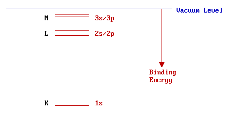
However, scientists working with x-rays tend to use the alternative nomenclature on the left and it is this nomenclature that is used in Auger spectroscopy. The designation of levels to the K,L,M,… shells is based on their having principal quantum numbers of 1,2,3,… respectively. It is convenient to expand the part of the energy scale close to the vacuum level in order to more clearly distinguish between the higher levels ....
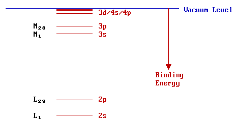
The numerical component of the KLM.. style of nomenclature is usually written as a subscript immediately following the main shell designation. Levels with a non-zero value of the orbital angular momentum quantum number ( l > 0), i.e. p,d,f,.. levels, show spin-orbit splitting. The magnitude of this splitting, however, is too small to be evident on this diagram - hence, the double subscript for these levels (i.e. L2,3 represents both the L2 and L3 levels).
Electronic Structure - Solid State
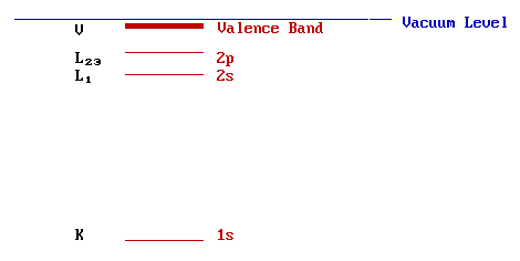
In the solid state the core levels of atoms are little perturbed and essentially remain as discrete, localized (i.e. atomic-like) levels. The valence orbitals, however, overlap significantly with those of neighboring atoms generating bands of spatially-delocalised energy levels. The energy level diagram for the solid is therefore closely resemblance of that of the corresponding isolated atom, except for the levels closest to the vacuum level. The diagram below shows the electronic structure of Na metal:
The Auger Process & Auger Spectroscopy
Now let us return to the subject of Auger spectroscopy - in the following discussion, the Auger process is illustrated using the K, L1 & L2,3 levels. These could be the inner core levels of an atom in either a molecular or solid-state environment.
Step I: Ionization
The Auger process is initiated by creation of a core hole - this is typically carried out by exposing the sample to a beam of high energy electrons (typically having a primary energy in the range 2 - 10 keV). Such electrons have sufficient energy to ionise all levels of the lighter elements, and higher core levels of the heavier elements.
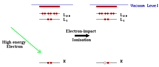
In the diagram above, ionisation is shown to occur by removal of a K-shell electron, but in practice such a crude method of ionisation will lead to ions with holes in a variety of inner shell levels.
In some studies, the initial ionisation process is instead carried out using soft x-rays ( hν = 1000 - 2000 eV ). In this case, the acronym XAES is sometimes used. As we shall see, however, this change in the method of ionisation has no significant effect on the final Auger spectrum.
Step II: Relaxation & Auger Emission
The ionized atom that remains after the removal of the core hole electron is, of course, in a highly excited state and will rapidly relax back to a lower energy state by one of two routes: X-ray fluorescence or Auger emission. We will only consider the latter mechanism, an example of which is illustrated schematically below ....
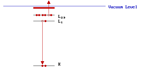
In this example, one electron falls from a higher level to fill an initial core hole in the K-shell and the energy liberated in this process is simultaneously transferred to a second electron ; a fraction of this energy is required to overcome the binding energy of this second electron, the remainder is retained by this emitted Auger electron as kinetic energy. In the Auger process illustrated, the final state is a doubly-ionized atom with core holes in the L1 and L2,3 shells.
We can make a rough estimate of the KE of the Auger electron from the binding energies of the various levels involved. In this particular example,
\[KE = ( E_K - E_{L1} ) - E_{L23} \label{eq1}\]
[ Why is this answer not likely to be very accurate ?]
The KE of the Auger electron is independent of the mechanism of initial core hole formation.
Equation \ref{eq1} can also be re-written in the form:
\[KE = E_K - ( E_{L1} + E_{L23} )\]
It should be clear from this expression that the latter two energy terms could be interchanged without any effect - i.e. it is actually impossible to say which electron fills the initial core hole and which is ejected as an Auger electron; they are indistinguishable.
An Auger transition is therefore characterized primarily by:
- the location of the initial hole
- the location of the final two holes
although the existence of different electronic states (terms) of the final doubly-ionized atom may lead to fine structure in high resolution spectra.
Step III: Analysis and Interpretation
When describing the transition, the initial hole location is given first, followed by the locations of the final two holes in order of decreasing binding energy, i.e. the transition illustrated is a KL1L2,3 transition. If we just consider these three electronic levels there are clearly several possible Auger transitions: specifically,
| K L1 L1 | K L1 L2,3 | K L2,3 L2,3 |
In general, since the initial ionization is non-selective and the initial hole may therefore be in various shells, there will be many possible Auger transitions for a given element - some weak, some strong in intensity. AUGER SPECTROSCOPY is based upon the measurement of the kinetic energies of the emitted electrons. Each element in a sample being studied will give rise to a characteristic spectrum of peaks at various kinetic energies.
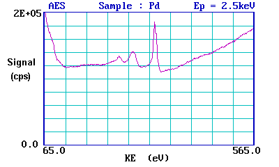
This is an Auger spectrum of Pd metal - generated using a 2.5 keV electron beam to produce the initial core vacancies and hence to stimulate the Auger emission process. The main peaks for palladium occur between 220 & 340 eV. The peaks are situated on a high background which arises from the vast number of so-called secondary electrons generated by a multitude of inelastic scattering processes.
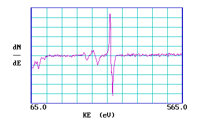
Auger spectra are also often shown in a differentiated form: the reasons for this are partly historical, partly because it is possible to actually measure spectra directly in this form and by doing so get a better sensitivity for detection. The plot below shows the same spectrum in such a differentiated form.
Summary
Auger Electron Spectroscopy (AES) is a surface-sensitive spectroscopic technique used for elemental analysis of surfaces; it offers
- high sensitivity (typically ca. 1% monolayer) for all elements except H and He.
- a means of monitoring surface cleanliness of samples
- quantitative compositional analysis of the surface region of specimens, by comparison with standard samples of known composition.
In addition, the basic technique has also been adapted for use in:
- Auger Depth Profiling: providing quantitative compositional information as a function of depth below the surface
- Scanning Auger Microscopy (SAM): providing spatially-resolved compositional information on heterogeneous samples


