
Ion-Selective Electrodes
- Page ID
- 78061

\( \newcommand{\vecs}[1]{\overset { \scriptstyle \rightharpoonup} {\mathbf{#1}} } \)
\( \newcommand{\vecd}[1]{\overset{-\!-\!\rightharpoonup}{\vphantom{a}\smash {#1}}} \)
\( \newcommand{\dsum}{\displaystyle\sum\limits} \)
\( \newcommand{\dint}{\displaystyle\int\limits} \)
\( \newcommand{\dlim}{\displaystyle\lim\limits} \)
\( \newcommand{\id}{\mathrm{id}}\) \( \newcommand{\Span}{\mathrm{span}}\)
( \newcommand{\kernel}{\mathrm{null}\,}\) \( \newcommand{\range}{\mathrm{range}\,}\)
\( \newcommand{\RealPart}{\mathrm{Re}}\) \( \newcommand{\ImaginaryPart}{\mathrm{Im}}\)
\( \newcommand{\Argument}{\mathrm{Arg}}\) \( \newcommand{\norm}[1]{\| #1 \|}\)
\( \newcommand{\inner}[2]{\langle #1, #2 \rangle}\)
\( \newcommand{\Span}{\mathrm{span}}\)
\( \newcommand{\id}{\mathrm{id}}\)
\( \newcommand{\Span}{\mathrm{span}}\)
\( \newcommand{\kernel}{\mathrm{null}\,}\)
\( \newcommand{\range}{\mathrm{range}\,}\)
\( \newcommand{\RealPart}{\mathrm{Re}}\)
\( \newcommand{\ImaginaryPart}{\mathrm{Im}}\)
\( \newcommand{\Argument}{\mathrm{Arg}}\)
\( \newcommand{\norm}[1]{\| #1 \|}\)
\( \newcommand{\inner}[2]{\langle #1, #2 \rangle}\)
\( \newcommand{\Span}{\mathrm{span}}\) \( \newcommand{\AA}{\unicode[.8,0]{x212B}}\)
\( \newcommand{\vectorA}[1]{\vec{#1}} % arrow\)
\( \newcommand{\vectorAt}[1]{\vec{\text{#1}}} % arrow\)
\( \newcommand{\vectorB}[1]{\overset { \scriptstyle \rightharpoonup} {\mathbf{#1}} } \)
\( \newcommand{\vectorC}[1]{\textbf{#1}} \)
\( \newcommand{\vectorD}[1]{\overrightarrow{#1}} \)
\( \newcommand{\vectorDt}[1]{\overrightarrow{\text{#1}}} \)
\( \newcommand{\vectE}[1]{\overset{-\!-\!\rightharpoonup}{\vphantom{a}\smash{\mathbf {#1}}}} \)
\( \newcommand{\vecs}[1]{\overset { \scriptstyle \rightharpoonup} {\mathbf{#1}} } \)
\(\newcommand{\longvect}{\overrightarrow}\)
\( \newcommand{\vecd}[1]{\overset{-\!-\!\rightharpoonup}{\vphantom{a}\smash {#1}}} \)
\(\newcommand{\avec}{\mathbf a}\) \(\newcommand{\bvec}{\mathbf b}\) \(\newcommand{\cvec}{\mathbf c}\) \(\newcommand{\dvec}{\mathbf d}\) \(\newcommand{\dtil}{\widetilde{\mathbf d}}\) \(\newcommand{\evec}{\mathbf e}\) \(\newcommand{\fvec}{\mathbf f}\) \(\newcommand{\nvec}{\mathbf n}\) \(\newcommand{\pvec}{\mathbf p}\) \(\newcommand{\qvec}{\mathbf q}\) \(\newcommand{\svec}{\mathbf s}\) \(\newcommand{\tvec}{\mathbf t}\) \(\newcommand{\uvec}{\mathbf u}\) \(\newcommand{\vvec}{\mathbf v}\) \(\newcommand{\wvec}{\mathbf w}\) \(\newcommand{\xvec}{\mathbf x}\) \(\newcommand{\yvec}{\mathbf y}\) \(\newcommand{\zvec}{\mathbf z}\) \(\newcommand{\rvec}{\mathbf r}\) \(\newcommand{\mvec}{\mathbf m}\) \(\newcommand{\zerovec}{\mathbf 0}\) \(\newcommand{\onevec}{\mathbf 1}\) \(\newcommand{\real}{\mathbb R}\) \(\newcommand{\twovec}[2]{\left[\begin{array}{r}#1 \\ #2 \end{array}\right]}\) \(\newcommand{\ctwovec}[2]{\left[\begin{array}{c}#1 \\ #2 \end{array}\right]}\) \(\newcommand{\threevec}[3]{\left[\begin{array}{r}#1 \\ #2 \\ #3 \end{array}\right]}\) \(\newcommand{\cthreevec}[3]{\left[\begin{array}{c}#1 \\ #2 \\ #3 \end{array}\right]}\) \(\newcommand{\fourvec}[4]{\left[\begin{array}{r}#1 \\ #2 \\ #3 \\ #4 \end{array}\right]}\) \(\newcommand{\cfourvec}[4]{\left[\begin{array}{c}#1 \\ #2 \\ #3 \\ #4 \end{array}\right]}\) \(\newcommand{\fivevec}[5]{\left[\begin{array}{r}#1 \\ #2 \\ #3 \\ #4 \\ #5 \\ \end{array}\right]}\) \(\newcommand{\cfivevec}[5]{\left[\begin{array}{c}#1 \\ #2 \\ #3 \\ #4 \\ #5 \\ \end{array}\right]}\) \(\newcommand{\mattwo}[4]{\left[\begin{array}{rr}#1 \amp #2 \\ #3 \amp #4 \\ \end{array}\right]}\) \(\newcommand{\laspan}[1]{\text{Span}\{#1\}}\) \(\newcommand{\bcal}{\cal B}\) \(\newcommand{\ccal}{\cal C}\) \(\newcommand{\scal}{\cal S}\) \(\newcommand{\wcal}{\cal W}\) \(\newcommand{\ecal}{\cal E}\) \(\newcommand{\coords}[2]{\left\{#1\right\}_{#2}}\) \(\newcommand{\gray}[1]{\color{gray}{#1}}\) \(\newcommand{\lgray}[1]{\color{lightgray}{#1}}\) \(\newcommand{\rank}{\operatorname{rank}}\) \(\newcommand{\row}{\text{Row}}\) \(\newcommand{\col}{\text{Col}}\) \(\renewcommand{\row}{\text{Row}}\) \(\newcommand{\nul}{\text{Nul}}\) \(\newcommand{\var}{\text{Var}}\) \(\newcommand{\corr}{\text{corr}}\) \(\newcommand{\len}[1]{\left|#1\right|}\) \(\newcommand{\bbar}{\overline{\bvec}}\) \(\newcommand{\bhat}{\widehat{\bvec}}\) \(\newcommand{\bperp}{\bvec^\perp}\) \(\newcommand{\xhat}{\widehat{\xvec}}\) \(\newcommand{\vhat}{\widehat{\vvec}}\) \(\newcommand{\uhat}{\widehat{\uvec}}\) \(\newcommand{\what}{\widehat{\wvec}}\) \(\newcommand{\Sighat}{\widehat{\Sigma}}\) \(\newcommand{\lt}{<}\) \(\newcommand{\gt}{>}\) \(\newcommand{\amp}{&}\) \(\definecolor{fillinmathshade}{gray}{0.9}\)So far you have learned that during the technique of potentiometry, the potential, or voltage, of an electrochemical cell is measured. The cell consists of both an indicator and reference electrode. Since the potential of the reference electrode is constant, it is the potential developed at the indicator electrode that contains information about the amount of analyte in a sample. During the measurement, there is little to no current flow. An electrochemical cell for making a potentiometric measurement with a membrane electrode (also known as an ion-selective electrode, ISE) is shown in Figure 1. As you can see the main difference between an ISE and the direct indicator electrode is in the ISE's composition.
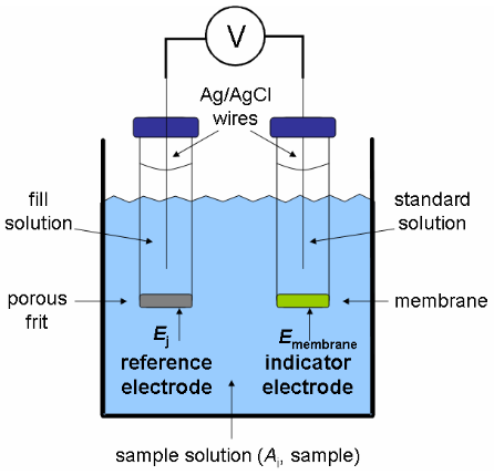
Figure 1. Electrochemical cell for making a potentiometric measurement with an ISE.
As indicated by their name, ion-selective electrodes possess a high degree of selectivity. The selectivity of the ISE is determined by the composition of the membrane. Ideally the membrane allows the uptake of only one specific ion into it. The analyte ion may be a cation or an anion. The three main components of making a measurement at an ISE are an inner reference, or standard, solution and an outer analyte, or sample, solution separated by a thin membrane. These components are shown in Figure 1. Redox processes do not occur at ISEs. The potential developed at the membrane is the result of either an ion exchange process or an ion transport process occurring at each interface between the membrane and solution. The basics of ion exchange and ion transport are reviewed in the next sections.
Ion Exchange Process
In the following ion exchange process, a lithium cation displaces a potassium cation from the organic anion, R- :
\[\mathrm{ {\color{Magenta} K}{\color{Blue} R} + {\color{Magenta} Li^+} \leftrightharpoons {\color{Magenta} Li}{\color{Blue} R} + {\color{Magenta} K^+}}\]
We can imbed the lipophilic R- in a membrane, as shown in Figure 2, and place it in a solution of Li+
\[\mathrm{ {\color{Magenta} K}{\color{Blue} R_{(mem)}} + {\color{Magenta} Li^+_{(aq)}} \leftrightharpoons {\color{Magenta} Li}{\color{Blue} R_{(mem)}} + {\color{Magenta} K^+_{(aq)}}}\]
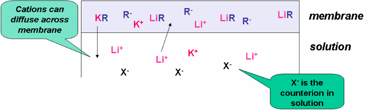
Figure 2. Ion-exchange process.
In order to construct an ion-selective electrode, we would add an inner reference solution to the other side of the membrane. This solution would contain a fixed concentration of the ion of interest, Li+ in this example. This is typically accomplished by placing a thin membrane at the end of the plastic tube and filling the tube with a standard (known concentration) solution of the analyte. As shown in Figure 1, a reference electrode is placed in the inner solution and a second reference electrode is in contact with the analyte (outer) solution. At each solution-membrane interface, an ion-exchange equilibrium is established. The partitioning of Li+ between the aqueous solution phase and the membrane phase depends on its activity, or concentration. The resulting charge separation at each interface results in a phase-boundary potential.8-10 If the analyte ion concentration on each side of the membrane was equal, the potential difference across the membrane would be zero. However, if the concentrations are not equal, a membrane potential will develop. The two reference electrodes (see Figure 1) measure the potential difference across the membrane.
Ion Transport with an Ionophore
Now that you understand the basics of ion exchange, let’s put a membrane, containing an ionophore, between an “unknown” analyte solution and a “known” reference solution (Figure 3). In this example, the analyte is A+. The ionophore is a neutral “carrier” molecule represented by the blue oval. Figure 4 shows the chemical structure of two ionophores. The ionophore cannot diffuse out of the membrane and but can “trap” the analyte ion (A+) at the interface between the solution and membrane. Without the ionophore, the analyte would be unable to partition into the organic membrane.
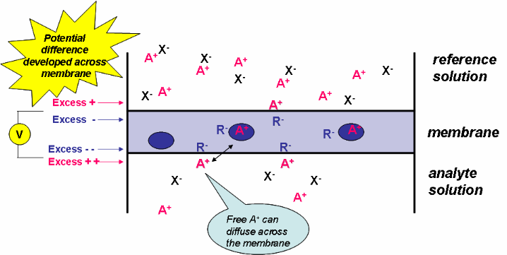
Figure 3. Development of a potential at an ISE.
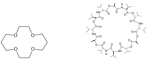
Figure 4. Chemical structures of a crown ether (left) and of valinomycin (right), two ionophores.
As with the ion-exchange process, equilibrium is established at both solution-membrane interfaces. The resulting charge separation at each interface leads to a phase-boundary potential.
Now that we have developed an electrical potential across the membrane, we need to find a way to measure it. As before, we put an internal reference electrode in the internal reference solution and an external reference electrode in the analyte solution, as shown in Figure 5. The potential difference measured at these two electrodes is the membrane potential.

Figure 5. Electrochemical cell for a potentiometric measurement with an ISE.
The Membrane
By now you have learned that the identity of the membrane determines the selectivity of the electrode. In other words the type of membrane used dictates which analyte you can detect. Therefore different electrodes are used for different ions. The membrane should also have low electronic conductivity. The membrane must have low solubility in the analyte solution – we don’t want it to dissolve!!
There are three main types of membranes. The electrodes are classified by the membrane material.
- Glass membrane electrodes: The most famous glass electrode determines H+ activity or pH (click here for the pH electrode section). The membrane is composed of a silicate glass. Glass electrodes can also be constructed that are sensitive to other cations such as sodium.
- Single crystal LaF3 is widely used to determine F-. The crystal is usually doped with europium to improve the conductivity. At each membrane-solution interface, the following equilibrium takes place:
\[\ce{LaF3} (s) \leftrightharpoons \ce{LaF2+} (s) + \ce{F-} (aq)\]
You can see that the formation of LaF2+ creates a charge at the surface. The equilibrium will be shifted to the right for the solution with a smaller F- concentration, and the potential will become more positive relative to the other side of the membrane. It is this potential difference across the LaF3 crystal membrane that is measured and related to F- concentration. The fluoride electrode is extremely selective for F- but can experience interference from OH- above pH 8. This electrode is used in one of the experiments listed at the end of this learning module. Click here to learn more.
- One of the most famous liquid membrane electrodes has been used for calcium determination. Initially, researchers attempted to use glass membrane electrodes (which had been successful for monovalent cations such as H+ and Na+) to detect divalent cations, such as Ca2+. When this was determined to be unfeasible, liquid membranes were developed. This electrode works by an ion-exchange process. The cation-exchanger is an aliphatic diester of phosphoric acid, (RO)2PO2-, where each R group is an aliphatic hydrocarbon chain containing between 8 and 16 carbons. The phosphate group can be protonated, but has a strong affinity for Ca2+. The cation exchanger is dissolved in an organic solvent and held in a porous compartment between the analyte solution and internal reference calcium chloride solution. The ion-exchanger uptakes Ca2+ into the membrane by the following mechanism, forming a complex with the structure shown in Figure 6:
\[\ce{Ca^2+}\, (aqueous) + \ce{2(RO)2PO2-}\, (organic) \leftrightharpoons \ce{[(RO)2PO2]2Ca}\, (organic)\]
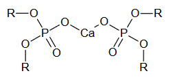
Figure 6. Calcium dialkyl phosphate complex.
Calcium ISEs are commonly used to measure calcium ion activity in biological fluids, as calcium ion is important in many physiological processes, such as bone formation.
- Ionophores, or chelating agents, that selectively complex ions include crown ethers and the antibiotic valinomycin (see Figure 4). The important feature of the neutral carrier molecule is its cavity which has dimensions approximately that of a molecule or ion. The valinomycin electrode was one of the first polymer membrane electrodes and is routinely used to determine potassium. The electron-rich center of valinomycin efficiently extracts K+ ions due to the similarity between the diameter of K+ and the inner diameter of the valinomycin molecule. The outer lipophilic part of the valinomycin molecule allows it to remain in the polymeric membrane. In the United States alone, nearly 200 million measurements are made annually of blood potassium levels using this electrode.11
Relationship Between Potential and Concentration
For all of the ISEs described above, the same equations can be used to predict the relationship between potential and analyte activity (A) or concentration.
The potential measured, Emeas, is the potential difference between the analyte (Eouter) side of the membrane and the reference (Einner) side of the membrane:
\[E_{meas} = E_\ce{outer} - E_\ce{inner} \tag{1}\]
The potential of each side is related to activity (A) or concentration as described by the Nernst equation, where z is the charge of the ion of interest:
\[E_{outer} = E^o − \dfrac{0.05916}{z} \log \dfrac{1}{A_{unk}} \tag{2}\]
\[E_{inner} = E^o - \dfrac{0.05916}{z} \log \dfrac{1}{A_{ref}} \tag{3}\]
Since Aref and Eo are both constant, Einner (equation 3) is constant. If equations 2 and 3 are plugged into equation 1, they combine to give the following:
\[E_{meas} = const + \dfrac{0.05916}{z} \log A_{unk}\tag{4}\]
Note that the “const” term contains Einner and the E0 from the Eouter term. Also, don’t forget the that –log(1/a) = log(a).
You can see that ISEs should exhibit a Nernstian response, as you previously learned for the direct indicator electrodes.
Selectivity of ISEs
You have learned that one of the most important analytical characteristics of ISEs is their selectivity; i.e. a specific ion electrode will only respond to the presence of one species. In reality, ion-selective electrodes can experience interferences by responding to the presence of other ions. Although the fluoride electrode comes close, no membrane is 100% specific for only one ion. Equation 4 assumes that all of the electrode response (Emeas) is due to one ion. Let’s call this analyte ion i and its activity Ai (note that the charge is now zi). We will call the interfering ion j with corresponding activity Aj and charge zj. We can account for the lack of 100% specificity by incorporating the activity of j and a selectivity coefficient (kij) into equation 4. This new equation is called the Nikolskii-Eisenman equation:
\[E_{meas} = const + \dfrac{0.05916}{z} \log(A_i + k_{ij} A_j^{\Large\frac{z_i}{z_j}}) \tag{5}\]
The selectivity coefficient is a numerical measure of how well the membrane can discriminate against the interfering ion. To put this in perspective, if an electrode has equivalent responses to the two ions, then kij = 1.0. As you can see from the equation, the smaller the kij values, the less impact the interfering ion will have on the measured potential. When kij values are less than 1, the ISE is more responsive to the analyte ion and when kij values are greater than 1, the ISE is more responsive to the interfering ion. For example, a kij value of 0.01 means that the electrode is 100 times more responsive to ion i over j.
Selectivity coefficients can be experimentally determined. Selectivity coefficients for some of the electrodes previously discussed are listed below.
| Analyte ion (i) | Interfering Ion (j) | kij |
|---|---|---|
|
K+ (valinomycin)a |
Na+ Ca2+, Mg2+ |
10-4 10-7 |
|
Ca2+ b |
Mg2+ K+ |
0.02 0.001 |
areference 12. breference 11.
Continue onto the next page to work on some problems about ISEs.
Problems
- Describe the difference between an ion exchange process and how an ionophore functions.
- The following calibration data was collected at a Pb2+ ISE. Assuming that the ionic strength remains constant and that the activity coefficient is 1.0, what is the Pb2+ concentration of a solution that gives a potential reading of 145 mV?
For some help with this problem, open up the following spreadsheet. Make sure that you are on the Pb2+ tab.
[Pb2+] (mol/L) E (mV) 5.00 x 10⁻⁵ 92 5.00 x 10⁻⁴ 121 5.00 x 10⁻³ 151 ? 145 - A fluoride ISE gives the following calibration data. What potential (mV) reading do you expect for the last solution?
For some help with this problem, open up the following spreadsheet. Make sure that you are on the F- tab.
[F- ] (mol/L) E (mV) 1.00 x 10⁻⁵ 235 5.00 x 10⁻⁵ 195 1.00 x 10⁻⁴ 175 5.00 x 10⁻⁴ ?
Further Reading on ISEs
For further reading on ISEs, refer to references 8 through 13 and the following online resources:
http://www.nico2000.net/Book/Guide1.html
Section on ISEs found at Chemistry Hypermedia Project
ISE products from GlobalSpec (an engineering search engine with free registration)
Point of care diagnostics: “Clinical Instrumentation Refresher Series: Ion Selective Electrodes” by William R. Hliwa, Western New York Microcomputer, Inc., April, 1998: available for purchase through Med TechNet Online Services.