7.7: Circular Dichroism Spectroscopy and its Application for Determination of Secondary Structure of Optically Active Species
- Page ID
- 55912
\( \newcommand{\vecs}[1]{\overset { \scriptstyle \rightharpoonup} {\mathbf{#1}} } \)
\( \newcommand{\vecd}[1]{\overset{-\!-\!\rightharpoonup}{\vphantom{a}\smash {#1}}} \)
\( \newcommand{\id}{\mathrm{id}}\) \( \newcommand{\Span}{\mathrm{span}}\)
( \newcommand{\kernel}{\mathrm{null}\,}\) \( \newcommand{\range}{\mathrm{range}\,}\)
\( \newcommand{\RealPart}{\mathrm{Re}}\) \( \newcommand{\ImaginaryPart}{\mathrm{Im}}\)
\( \newcommand{\Argument}{\mathrm{Arg}}\) \( \newcommand{\norm}[1]{\| #1 \|}\)
\( \newcommand{\inner}[2]{\langle #1, #2 \rangle}\)
\( \newcommand{\Span}{\mathrm{span}}\)
\( \newcommand{\id}{\mathrm{id}}\)
\( \newcommand{\Span}{\mathrm{span}}\)
\( \newcommand{\kernel}{\mathrm{null}\,}\)
\( \newcommand{\range}{\mathrm{range}\,}\)
\( \newcommand{\RealPart}{\mathrm{Re}}\)
\( \newcommand{\ImaginaryPart}{\mathrm{Im}}\)
\( \newcommand{\Argument}{\mathrm{Arg}}\)
\( \newcommand{\norm}[1]{\| #1 \|}\)
\( \newcommand{\inner}[2]{\langle #1, #2 \rangle}\)
\( \newcommand{\Span}{\mathrm{span}}\) \( \newcommand{\AA}{\unicode[.8,0]{x212B}}\)
\( \newcommand{\vectorA}[1]{\vec{#1}} % arrow\)
\( \newcommand{\vectorAt}[1]{\vec{\text{#1}}} % arrow\)
\( \newcommand{\vectorB}[1]{\overset { \scriptstyle \rightharpoonup} {\mathbf{#1}} } \)
\( \newcommand{\vectorC}[1]{\textbf{#1}} \)
\( \newcommand{\vectorD}[1]{\overrightarrow{#1}} \)
\( \newcommand{\vectorDt}[1]{\overrightarrow{\text{#1}}} \)
\( \newcommand{\vectE}[1]{\overset{-\!-\!\rightharpoonup}{\vphantom{a}\smash{\mathbf {#1}}}} \)
\( \newcommand{\vecs}[1]{\overset { \scriptstyle \rightharpoonup} {\mathbf{#1}} } \)
\( \newcommand{\vecd}[1]{\overset{-\!-\!\rightharpoonup}{\vphantom{a}\smash {#1}}} \)
\(\newcommand{\avec}{\mathbf a}\) \(\newcommand{\bvec}{\mathbf b}\) \(\newcommand{\cvec}{\mathbf c}\) \(\newcommand{\dvec}{\mathbf d}\) \(\newcommand{\dtil}{\widetilde{\mathbf d}}\) \(\newcommand{\evec}{\mathbf e}\) \(\newcommand{\fvec}{\mathbf f}\) \(\newcommand{\nvec}{\mathbf n}\) \(\newcommand{\pvec}{\mathbf p}\) \(\newcommand{\qvec}{\mathbf q}\) \(\newcommand{\svec}{\mathbf s}\) \(\newcommand{\tvec}{\mathbf t}\) \(\newcommand{\uvec}{\mathbf u}\) \(\newcommand{\vvec}{\mathbf v}\) \(\newcommand{\wvec}{\mathbf w}\) \(\newcommand{\xvec}{\mathbf x}\) \(\newcommand{\yvec}{\mathbf y}\) \(\newcommand{\zvec}{\mathbf z}\) \(\newcommand{\rvec}{\mathbf r}\) \(\newcommand{\mvec}{\mathbf m}\) \(\newcommand{\zerovec}{\mathbf 0}\) \(\newcommand{\onevec}{\mathbf 1}\) \(\newcommand{\real}{\mathbb R}\) \(\newcommand{\twovec}[2]{\left[\begin{array}{r}#1 \\ #2 \end{array}\right]}\) \(\newcommand{\ctwovec}[2]{\left[\begin{array}{c}#1 \\ #2 \end{array}\right]}\) \(\newcommand{\threevec}[3]{\left[\begin{array}{r}#1 \\ #2 \\ #3 \end{array}\right]}\) \(\newcommand{\cthreevec}[3]{\left[\begin{array}{c}#1 \\ #2 \\ #3 \end{array}\right]}\) \(\newcommand{\fourvec}[4]{\left[\begin{array}{r}#1 \\ #2 \\ #3 \\ #4 \end{array}\right]}\) \(\newcommand{\cfourvec}[4]{\left[\begin{array}{c}#1 \\ #2 \\ #3 \\ #4 \end{array}\right]}\) \(\newcommand{\fivevec}[5]{\left[\begin{array}{r}#1 \\ #2 \\ #3 \\ #4 \\ #5 \\ \end{array}\right]}\) \(\newcommand{\cfivevec}[5]{\left[\begin{array}{c}#1 \\ #2 \\ #3 \\ #4 \\ #5 \\ \end{array}\right]}\) \(\newcommand{\mattwo}[4]{\left[\begin{array}{rr}#1 \amp #2 \\ #3 \amp #4 \\ \end{array}\right]}\) \(\newcommand{\laspan}[1]{\text{Span}\{#1\}}\) \(\newcommand{\bcal}{\cal B}\) \(\newcommand{\ccal}{\cal C}\) \(\newcommand{\scal}{\cal S}\) \(\newcommand{\wcal}{\cal W}\) \(\newcommand{\ecal}{\cal E}\) \(\newcommand{\coords}[2]{\left\{#1\right\}_{#2}}\) \(\newcommand{\gray}[1]{\color{gray}{#1}}\) \(\newcommand{\lgray}[1]{\color{lightgray}{#1}}\) \(\newcommand{\rank}{\operatorname{rank}}\) \(\newcommand{\row}{\text{Row}}\) \(\newcommand{\col}{\text{Col}}\) \(\renewcommand{\row}{\text{Row}}\) \(\newcommand{\nul}{\text{Nul}}\) \(\newcommand{\var}{\text{Var}}\) \(\newcommand{\corr}{\text{corr}}\) \(\newcommand{\len}[1]{\left|#1\right|}\) \(\newcommand{\bbar}{\overline{\bvec}}\) \(\newcommand{\bhat}{\widehat{\bvec}}\) \(\newcommand{\bperp}{\bvec^\perp}\) \(\newcommand{\xhat}{\widehat{\xvec}}\) \(\newcommand{\vhat}{\widehat{\vvec}}\) \(\newcommand{\uhat}{\widehat{\uvec}}\) \(\newcommand{\what}{\widehat{\wvec}}\) \(\newcommand{\Sighat}{\widehat{\Sigma}}\) \(\newcommand{\lt}{<}\) \(\newcommand{\gt}{>}\) \(\newcommand{\amp}{&}\) \(\definecolor{fillinmathshade}{gray}{0.9}\)Circular dichroism (CD) spectroscopy is one of few structure assessmet methods that can be utilized as an alternative and amplification to many conventional analysis techniques with advatages such as rapid data collection and ease of use. Since most of the efforts and time spent in advancement of chemical sciences are devoted to elucidation and analysis of structure and composition of synthesized molecules or isolated natural products rather than their preparation, one should be aware of all the relevant techniques available and know which instrument can be employed as an alternative to any other technique.
The aim of this module is to introduce CD technique and discuss what kind of information one can collect using CD. Additionally, the advantages of CD compared to other analysis techniques and its limitations will be shown.
Optical Activity
As CD spectroscopy can analyze only optically active species, it is convenient to start the module with a brief introduction of optical activity. In nature almost every life form is handed, meaning that there is certain degree of asymmetry, just like in our hands. One cannot superimpose right hand on the left because they are non-identical mirror images of one another. So are the chiral (handed) molecules, they exist as enantiomers, which mirror images of each other (Figure \(\PageIndex{1}\)). One interesting phenomena related to chiral molecules is their ability to rotate plane of polarized light. Optical activity property is used to determine specific rotation, [ α ]Tλ, of pure enantiomer. This feature is used in polarimetery to find the enantiomeric excess, (ee), present in sample.
Circular Dichroism
Circular dichroism (CD) spectroscopy is a powerful yet straightforward technique for examining different aspects of optically active organic and inorganic molecules. Circular dichroism has applications in variety of modern research fields ranging from biochemistry to inorganic chemistry. Such widespread use of the technique arises from its essential property of providing structural information that cannot be acquired by other means. One other laudable feature of CD is its being a quick, easy technique that makes analysis a matter of minutes. Nevertheless, just like all methods, CD has a number of limitations, which will be discussed while comparing CD to other analysis techniques.
CD spectroscopy and related techniques were considered as esoteric analysis techniques needed and accessible only to a small clandestine group of professionals. In order to make the reader more familiar with the technique, first of all, the principle of operation of CD and its several types, as well as related techniques will be shown. Afterwards, sample preparation and instrument use will be covered for protein secondary structure study case.
Depending on the light source used for generation of circularly polarized light, there are:
- Far UV CD, used to study secondary structure proteins.
- Near UV CD, used to investigate tertiary structure of proteins.
- Visible CD, used for monitoring metal ion protein interactions.
Principle of Operation
In the CD spectrometer the sample is places in a cuvette and a beam of light is passed through the sample. The light (in the present context all electromagnetic waves will be refer to as light) coming from source is subjected to circular polarization, meaning that its plane of polarization is made to rotate either clockwise (right circular polarization) or anti-clockwise (left circular polarization) with time while propagating (Figure \(\PageIndex{2}\)).
The sample is, firstly irradiated with left rotating polarized light, and the absorption is determined by \ref{1}. A second irradiation is performed with right polarized light. Now, due to the intrinsic asymmetry of chiral molecules, they will interact with circularly polarized light differently according to the direction of rotation there is going to be a tendency to absorb more for one of rotation directions. The difference between absorption of left and right circularly polarized light is the data, which is obtained from \ref{2}, where εL and εR are the molar extinction coefficients for left and right circularly polarized light, c is the molar concentration, l is the path length, the cuvette width (in cm). The difference in absorption can be related to difference in extinction, Δε, by \ref{3}.
\[ A\ = \varepsilon c l \label{1} \]
\[ \Delta A\ =\ A_{L}-A_{R}\ =\ (\varepsilon _{L}\ -\ \varepsilon _{R} ) c l \label{2} \]
\[ \Delta \varepsilon \ =\ \varepsilon _{L} \ -\ \varepsilon _{R} \label{3} \]
Usually, due to historical reasons the CD is reported not only as difference in absorption or extinction coefficients but as degree of ellipticity, [θ]. The relationship between [θ] and Δε is given by \ref{4}.
\[ [\theta ]\ =\ 3,298 \Delta \varepsilon \label{4} \]
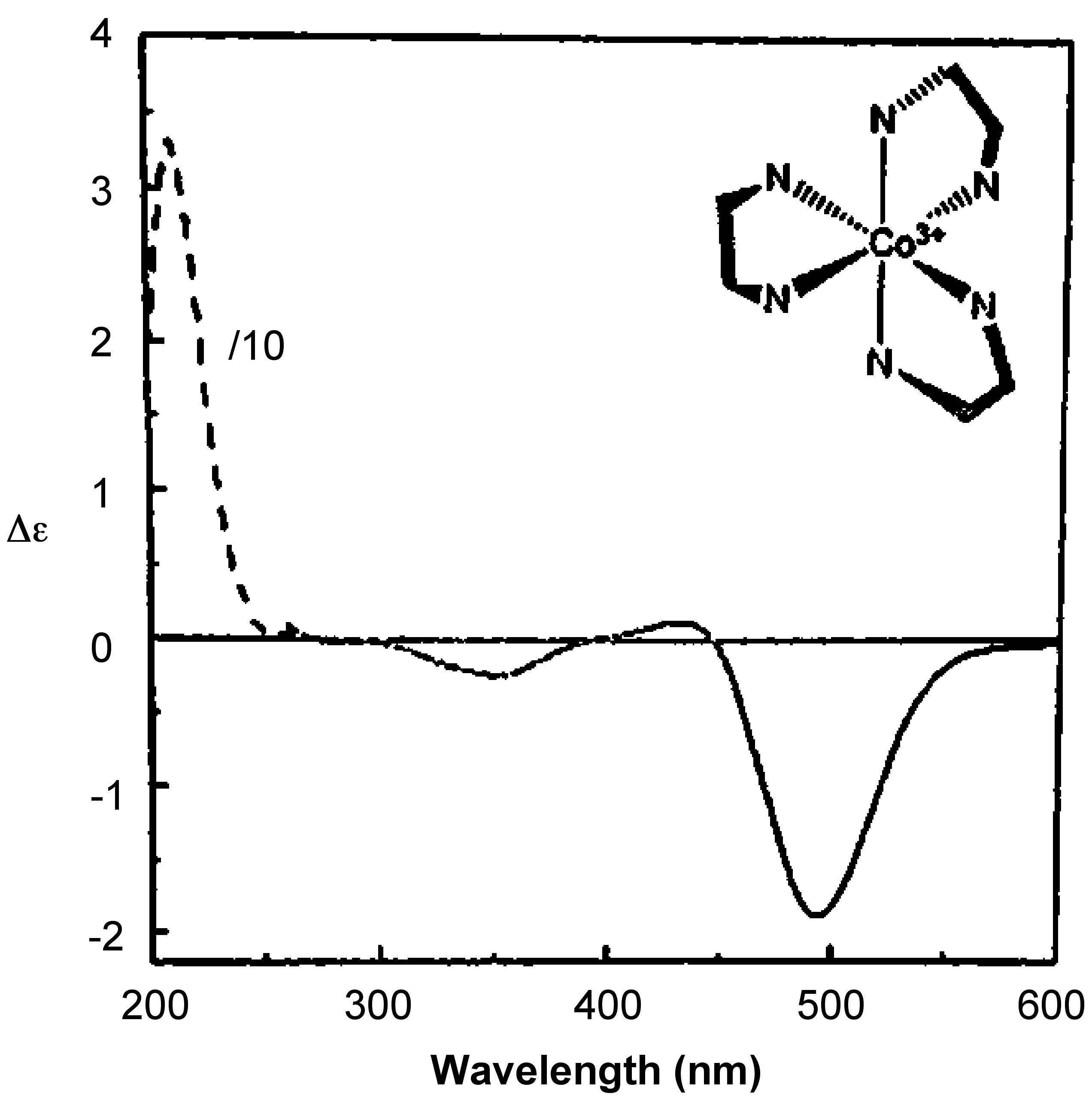
Since the absorption is monitored in a range of wavelengths, the output is a plot of [θ] versus wavelength or Δε versus wavelength. Figure \(\PageIndex{3}\) shows the CD spectrum of Δ–[Co(en)3]Cl3.

Related Techniques
Magnetic Circular Dichroism
Magnetic circular dichroism (MCD) is a sister technique to CD, but there are several distinctions:
- MCD does not require the sample to possess intrinsic asymmetry (i.e., chirality/optical activity), because optical activity is induced by applying magnetic field parallel to light.
- MCD and CD have different selection rules, thus information obtained from these two sister techniques is different. CD is good for assessing environment of the samples’ absorbing part while MCD is superior for obtaining detailed information about electronic structure of absorbing part.
MCD is powerful method for studying magnetic properties of materials and has recently been employed for analysis of iron-nitrogen compound, the strongest magnet known. Moreover, MCD and its variation, variable temperature MCD are complementary techniques to Mossbauer spectroscopy and electron paramagnetic resonance (EPR) spectroscopy. Hence, these techniques can give useful amplification to the chapter about Mossbauer and EPR spectroscopy.
Linear Dichroism
Linear dichrosim (LD) is also a very closely related technique to CD in which the difference between absorbance of perpendicularly and parallel polarized light is measured. In this technique the plane of polarization of light does not rotate. LD is used to determine the orientation of absorbing parts in space.
Advantages and Limitations of CD
Just like any other instrument CD has its strengths and limits. The comparison between CD and NMR shown in Table \(\PageIndex{1}\) gives a good sense of capabilities of CD.
| CD | NMR |
|---|---|
| Molecules of any size can be studied | There is size limitation |
| The experiments are quick to perform; single wavelength measurements require milliseconds | This is not the case all of the time. |
| Unique sensitivity to asymmetry in sample's structure. | Special conditions are required to differentiate between enantiomers. |
| Can work with very small concentrations, by lengthening the cuvette width until discernable absorption is achieved. | There is a limit to sensitivity of instrument. |
| Timescale is much shorter (UV) thus allowing to study dynamic systems and kinetics. | Timescale is long, use of radio waves gives average of all dynamic systems. |
| Only qualitative analysis of data is possible. | Quantitative data analysis can be performed to estimate chemical composition. |
| Does not provide atomic level structure analysis | Very powerful for atomic level analysis, providing essential information about chemical bonds in system. |
| The observed spectrum is not enough for claiming one and only possible structure | The NMR spectrum is key information for assigning a unique structure. |
What Kind of Data is Obtained from CD?
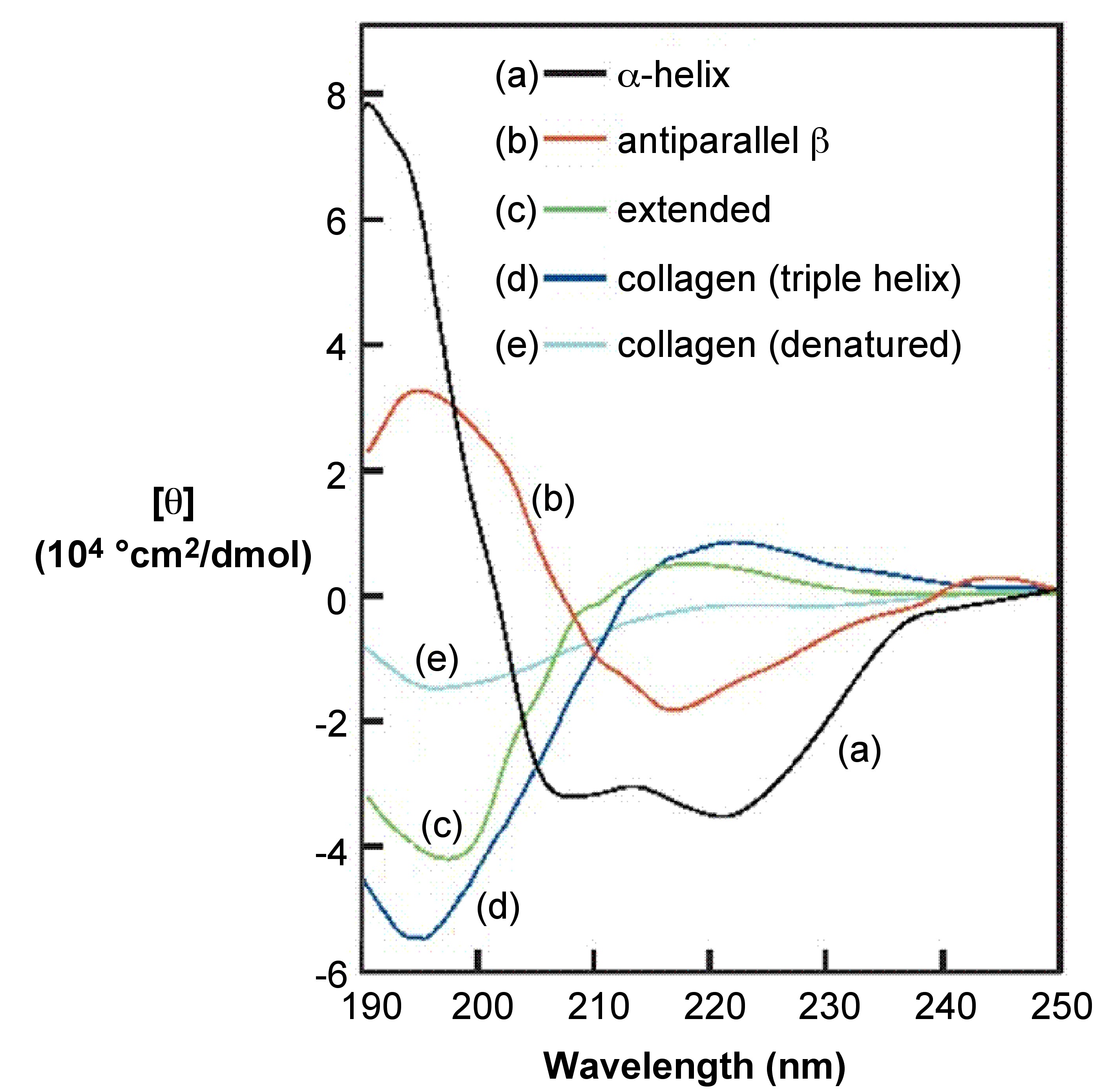
One effective way to demonstrate capabilities of CD spectroscopy is to cover the protein secondary structure study case, since CD spectroscopy is well-established technique for elucidation of secondary structure of proteins as well as any other macromolecules. By using CD one can estimate the degree of conformational order (what percent of the sample proteins is in α-helix and/or β-sheet conformation), see Figure \(\PageIndex{4}\).

Key points for visual estimation of secondary structure by looking at a CD spectrum:
- α-helical proteins have negative bands at 222 nm and 208 nm and a positive band at 193 nm.
- β-helices have negative bands at 218 nm and positive bands at 195 nm.
- Proteins lacking any ordered secondary structure will not have any peaks above 210 nm.
Since the CD spectra of proteins uniquely represent their conformation, CD can be used to monitor structural changes (due to complex formation, folding/unfolding, denaturation because of rise in temperature, denaturants, change in amino acid sequence/mutation, etc. ) in dynamic systems and to study kinetics of protein. In other words CD can be used to perform stability investigations and interaction modeling.
CD Instrument
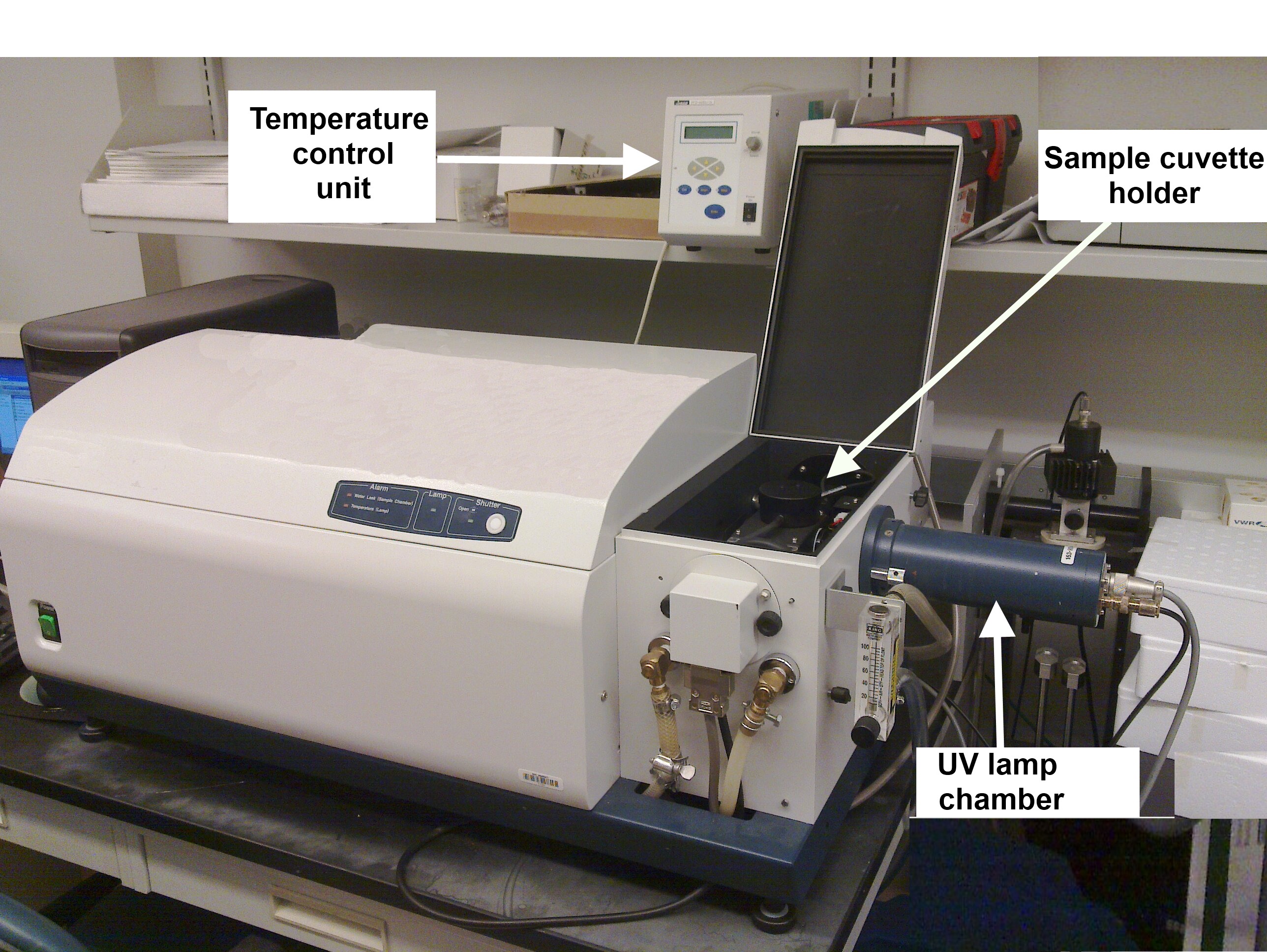
Figure \(\PageIndex{5}\) shows a typical CD instrument.

Protocol for Collecting a CD Spectrum
Most of proteins and peptides will require using buffers in order to prevent denaturation. Caution should be shown to avoid using any optically active buffers. Clear solutions are required. CD is taken in high transparency quartz cuvettes to ensure least interference. There are cuvettes available that have path-length ranging from 0.01 cm to 1 cm. Depending on UV activity of buffers used one should choose a cuvette with path-length (distance the beam of light passes through the sample) that compensates for UV absorbance of buffer. Solutions should be prepared according to cuvette that will be used, see Table \(\PageIndex{2}\).
| Cuvette Path (cm) | Concentration of Sample (mg/mL) |
|---|---|
| 0.01-0.02 | 0.2-1.0 |
| 0.1 | 0.05-0.2 |
| 1 | 0.005-0.01 |
Besides, just like salts used to prepare pallets in FT-IR, the buffers in CD will show cutoffs at a certain point in low wavelength region, meaning that buffers start to absorb after certain wavelengh. The cutoff values for most of common buffers are known and can be found from manufacturer. Oxygen absorbs light below 200 nm. Therefore, in order to remove interference buffers should be prepared from distilled water or the water should be degassed before use. Another important point is to accurately determine concentration of sample, because concentration should be known for CD data analysis. Concentration of sample can be determined from extinction coefficients, if such are reported in literature also for protein samples quantitative amino acid analysis can be used.
Many CD instrument come bundled with a sample compartment temperature control unit. This is very handy when doing stability and unfolding/denaturation studies of proteins. Check to make sure the heat sink is filled with water. Turn the temperature control unit on and set to chosen temperature.
UV source in CD is very powerful lamp and can generates large amounts of Ozone in its chamber. Ozone significantly reduces the life of the lamp. Therefore, oxygen should be removed before turning on the main lamp (otherwise it will be converted to ozone near lamp). For this purpose nitrogen gas is constantly flushed into lamp compartment. Let Nitrogen flush at least for 15 min. before turning on the lamp.
Collecting Spectra for Blank, Water, Buffer Background, and Sample
- Collect spectrum of air blank (Figure \(\PageIndex{6}\)). This will be essentially a line lying on x-axis of spectrum, zero absorbance.
- Fill the cuvette with water and take a spectrum.
- Water droplets left in cuvette may change concentration of your sample, especially when working with dilute samples. Hence, it is important to thoroughly dry the cuvette. After drying the cuvette, collect spectrum of buffer of exactly same concentration as used for sample (Figure \(\PageIndex{6}\)). This is the step where buffer is confirmed to be suitable spectrum of the buffer and water should overlap within experimental error, except for low wavelength region where signal-to-noise ratio is low.
- Clean the cuvette as described above and fill with sample solution. Collect the CD spectrum for three times for better accuracy (Figure \(\PageIndex{6}\)). For proteins multiple scans should overlap and not drift with time.

Data Handling and Analysis
After saving the data for both the spectra of the sample and blank is smoothed using built-in commands of controller software. The smoothed baseline is subtracted from the smoothed spectrum of the sample. The next step is to use software bundles which have algorithms for estimating secondary structure of proteins. Input the data into the software package of choice and process it. The output from algorithms will be the percentage of a particular secondary structure conformation in sample. The data shown in Figure \(\PageIndex{7}\) lists commonly used methods and compares them for several proteins. The estimated secondary structure is compared to X-ray data, and one can see that it is best to use several methods for best accuracy.

Conclusion
What advantages CD has over other analysis methods? CD spectroscopy is an excellent, rapid method for assessing the secondary structure of proteins and performing studies of dynamic systems like folding and binding of proteins. It worth noting that CD does not provide information about the position of those subunits with specific conformation. However, CD outrivals other techniques in rapid assessing of the structure of unknown protein samples and in monitoring structural changes of known proteins caused by ligation and complex formation, temperature change, mutations, denaturants. CD is also widely used to juxtapose fused proteins with wild type counterparts, because CD spectra can tell whether the fused protein retained the structure of wild type or underwent changes.


