23.3: Membrane Ion-Selective Electrodes
- Page ID
- 333590
\( \newcommand{\vecs}[1]{\overset { \scriptstyle \rightharpoonup} {\mathbf{#1}} } \)
\( \newcommand{\vecd}[1]{\overset{-\!-\!\rightharpoonup}{\vphantom{a}\smash {#1}}} \)
\( \newcommand{\dsum}{\displaystyle\sum\limits} \)
\( \newcommand{\dint}{\displaystyle\int\limits} \)
\( \newcommand{\dlim}{\displaystyle\lim\limits} \)
\( \newcommand{\id}{\mathrm{id}}\) \( \newcommand{\Span}{\mathrm{span}}\)
( \newcommand{\kernel}{\mathrm{null}\,}\) \( \newcommand{\range}{\mathrm{range}\,}\)
\( \newcommand{\RealPart}{\mathrm{Re}}\) \( \newcommand{\ImaginaryPart}{\mathrm{Im}}\)
\( \newcommand{\Argument}{\mathrm{Arg}}\) \( \newcommand{\norm}[1]{\| #1 \|}\)
\( \newcommand{\inner}[2]{\langle #1, #2 \rangle}\)
\( \newcommand{\Span}{\mathrm{span}}\)
\( \newcommand{\id}{\mathrm{id}}\)
\( \newcommand{\Span}{\mathrm{span}}\)
\( \newcommand{\kernel}{\mathrm{null}\,}\)
\( \newcommand{\range}{\mathrm{range}\,}\)
\( \newcommand{\RealPart}{\mathrm{Re}}\)
\( \newcommand{\ImaginaryPart}{\mathrm{Im}}\)
\( \newcommand{\Argument}{\mathrm{Arg}}\)
\( \newcommand{\norm}[1]{\| #1 \|}\)
\( \newcommand{\inner}[2]{\langle #1, #2 \rangle}\)
\( \newcommand{\Span}{\mathrm{span}}\) \( \newcommand{\AA}{\unicode[.8,0]{x212B}}\)
\( \newcommand{\vectorA}[1]{\vec{#1}} % arrow\)
\( \newcommand{\vectorAt}[1]{\vec{\text{#1}}} % arrow\)
\( \newcommand{\vectorB}[1]{\overset { \scriptstyle \rightharpoonup} {\mathbf{#1}} } \)
\( \newcommand{\vectorC}[1]{\textbf{#1}} \)
\( \newcommand{\vectorD}[1]{\overrightarrow{#1}} \)
\( \newcommand{\vectorDt}[1]{\overrightarrow{\text{#1}}} \)
\( \newcommand{\vectE}[1]{\overset{-\!-\!\rightharpoonup}{\vphantom{a}\smash{\mathbf {#1}}}} \)
\( \newcommand{\vecs}[1]{\overset { \scriptstyle \rightharpoonup} {\mathbf{#1}} } \)
\(\newcommand{\longvect}{\overrightarrow}\)
\( \newcommand{\vecd}[1]{\overset{-\!-\!\rightharpoonup}{\vphantom{a}\smash {#1}}} \)
\(\newcommand{\avec}{\mathbf a}\) \(\newcommand{\bvec}{\mathbf b}\) \(\newcommand{\cvec}{\mathbf c}\) \(\newcommand{\dvec}{\mathbf d}\) \(\newcommand{\dtil}{\widetilde{\mathbf d}}\) \(\newcommand{\evec}{\mathbf e}\) \(\newcommand{\fvec}{\mathbf f}\) \(\newcommand{\nvec}{\mathbf n}\) \(\newcommand{\pvec}{\mathbf p}\) \(\newcommand{\qvec}{\mathbf q}\) \(\newcommand{\svec}{\mathbf s}\) \(\newcommand{\tvec}{\mathbf t}\) \(\newcommand{\uvec}{\mathbf u}\) \(\newcommand{\vvec}{\mathbf v}\) \(\newcommand{\wvec}{\mathbf w}\) \(\newcommand{\xvec}{\mathbf x}\) \(\newcommand{\yvec}{\mathbf y}\) \(\newcommand{\zvec}{\mathbf z}\) \(\newcommand{\rvec}{\mathbf r}\) \(\newcommand{\mvec}{\mathbf m}\) \(\newcommand{\zerovec}{\mathbf 0}\) \(\newcommand{\onevec}{\mathbf 1}\) \(\newcommand{\real}{\mathbb R}\) \(\newcommand{\twovec}[2]{\left[\begin{array}{r}#1 \\ #2 \end{array}\right]}\) \(\newcommand{\ctwovec}[2]{\left[\begin{array}{c}#1 \\ #2 \end{array}\right]}\) \(\newcommand{\threevec}[3]{\left[\begin{array}{r}#1 \\ #2 \\ #3 \end{array}\right]}\) \(\newcommand{\cthreevec}[3]{\left[\begin{array}{c}#1 \\ #2 \\ #3 \end{array}\right]}\) \(\newcommand{\fourvec}[4]{\left[\begin{array}{r}#1 \\ #2 \\ #3 \\ #4 \end{array}\right]}\) \(\newcommand{\cfourvec}[4]{\left[\begin{array}{c}#1 \\ #2 \\ #3 \\ #4 \end{array}\right]}\) \(\newcommand{\fivevec}[5]{\left[\begin{array}{r}#1 \\ #2 \\ #3 \\ #4 \\ #5 \\ \end{array}\right]}\) \(\newcommand{\cfivevec}[5]{\left[\begin{array}{c}#1 \\ #2 \\ #3 \\ #4 \\ #5 \\ \end{array}\right]}\) \(\newcommand{\mattwo}[4]{\left[\begin{array}{rr}#1 \amp #2 \\ #3 \amp #4 \\ \end{array}\right]}\) \(\newcommand{\laspan}[1]{\text{Span}\{#1\}}\) \(\newcommand{\bcal}{\cal B}\) \(\newcommand{\ccal}{\cal C}\) \(\newcommand{\scal}{\cal S}\) \(\newcommand{\wcal}{\cal W}\) \(\newcommand{\ecal}{\cal E}\) \(\newcommand{\coords}[2]{\left\{#1\right\}_{#2}}\) \(\newcommand{\gray}[1]{\color{gray}{#1}}\) \(\newcommand{\lgray}[1]{\color{lightgray}{#1}}\) \(\newcommand{\rank}{\operatorname{rank}}\) \(\newcommand{\row}{\text{Row}}\) \(\newcommand{\col}{\text{Col}}\) \(\renewcommand{\row}{\text{Row}}\) \(\newcommand{\nul}{\text{Nul}}\) \(\newcommand{\var}{\text{Var}}\) \(\newcommand{\corr}{\text{corr}}\) \(\newcommand{\len}[1]{\left|#1\right|}\) \(\newcommand{\bbar}{\overline{\bvec}}\) \(\newcommand{\bhat}{\widehat{\bvec}}\) \(\newcommand{\bperp}{\bvec^\perp}\) \(\newcommand{\xhat}{\widehat{\xvec}}\) \(\newcommand{\vhat}{\widehat{\vvec}}\) \(\newcommand{\uhat}{\widehat{\uvec}}\) \(\newcommand{\what}{\widehat{\wvec}}\) \(\newcommand{\Sighat}{\widehat{\Sigma}}\) \(\newcommand{\lt}{<}\) \(\newcommand{\gt}{>}\) \(\newcommand{\amp}{&}\) \(\definecolor{fillinmathshade}{gray}{0.9}\)If metals were the only useful materials for constructing indicator electrodes, then there would be few useful applications of potentiometry. In 1906, Cremer discovered that the potential difference across a thin glass membrane is a function of pH when opposite sides of the membrane are in contact with solutions that have different concentrations of H3O+. The existence of this membrane potential led to the development of a new class of indicator electrodes, which we call ion-selective electrodes (ISEs). In addition to the glass pH electrode, ion-selective electrodes are available for a wide range of ions. It also is possible to construct a membrane electrode for a neutral analyte by using a chemical reaction to generate an ion that is monitored with an ion-selective electrode. The development of new ion-selective membrane electrodes continues to be an active area of research.
Classification of Ions-Selective Membranes
There are two broad classes of materials that are used as membranes: crystalline solid-state membranes and non-crystalline membranes. Examples of crystalline solid-state membranes are single crystals of LaF3 and polycrystalline AgS. Examples non-crystalline membranes are glass and hydrophobic membranes that hold a liquid ion-exchanger. Each of these are considered below.
Properties of Ion-Selective Membranes
To be useful, an ion-selective membrane must be structurally stable (a crystalline membrane that is soluble, for example, is not structurally stable), capable of being machined to a suitable size and shape that can be incorporated into the indicator electrode in a potentiometric electrochemical cell, electrically conductive so it is possible to measure the electrochemical cell's potential, and selective toward the analyte.
The Membrane's Boundary Potential
Figure \(\PageIndex{1}\) shows a typical potentiometric electrochemical cell equipped with an ion-selective electrode. The short hand notation for this cell is
\[\text { ref (sample) }\left\|\mathrm{A}_{\text { samp }}\left(a q, a_{\mathrm{A_{\text{samp}}}}=x\right) | \text{membrane} | \mathrm{A}_{\text { int }}\left(a q, a_{\mathrm{A_{\text{int}}}}=y\right)\right\| \text { ref (internal) } \nonumber \]
where the ion-selective membrane separates the two solutions that contain analyte with activities of x and y: the sample solution and the ion-selective electrode’s internal solution. The potential of this electrochemical cell
\[E_\text{cell} = E_\text{ref(int)} - E_\text{ref(samp)} + E_\text{mem} \label{membrane1} \]
includes the potential of each reference electrode and the difference in potential across the membrane, Emem, which is the membrane's boundary potential. The notations ref(sample) and ref(internal) represent a reference electrode immersed in the sample and a reference electrode immersed in the ion-selective electrode's internal solution. Because the potential of the two reference electrodes are constant, any change in Ecell reflects a change in the membrane’s boundary potential.
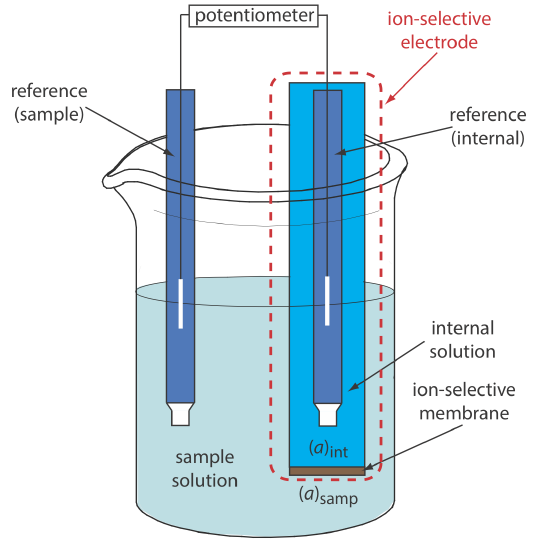
The analyte’s interaction with the membrane generates a boundary potential if there is a difference in its activity on the membrane’s two sides. Current is carried through the membrane by the movement of either the analyte or an ion already present in the membrane’s matrix. The membrane potential is given by the following Nernst-like equation
\[E_{\mathrm{mem}}=E_{\mathrm{asym}}-\frac{R T}{z F} \ln \frac{\left(a_{A}\right)_{\mathrm{int}}}{\left(a_{A}\right)_{\mathrm{samp}}} \label{membrane2} \]
where (aA)samp is the analyte’s activity in the sample, (aA)int is the analyte’s activity in the ion-selective electrode’s internal solution, and z is the analyte’s charge. Ideally, Emem is zero when (aA)int = (aA)samp. The term Easym, which is an asymmetry potential, accounts for the fact that Emem usually is not zero under these conditions.
For now we simply note that a difference in the analyte’s activity results in the membrane's boundary potential. As we consider different types of ion-selective electrodes, we will explore more specifically the source of the membrane potential.
Substituting Equation \ref{membrane2} into Equation \ref{membrane1}, assuming a temperature of 25oC, and rearranging gives
\[E_{\mathrm{cell}}=K+\frac{0.05916}{z} \log \left(a_{A}\right)_{\mathrm{samp}} \label{membrane3} \]
where K is a constant that includes the potentials of the two reference electrodes, the asymmetry potential, and the analyte's activity in the internal solution. Equation \ref{membrane3} is a general equation and applies to all types of ion-selective electrodes.
Membrane Selectivity
The membrane's boundary potential results from a chemical interaction between the analyte and active sites on the membrane’s surface. Because the signal depends on a chemical process, most membranes are not selective toward a single analyte. Instead, the membrane's boundary potential is proportional to the concentration of each ion that interacts with the membrane’s active sites. We can rewrite Equation \ref{membrane3} to include the contribution to the potential of an interferent, I
\[E_\text{cell} = K + \frac {0.05916} {z_A} \log \left\{ a_A + K_{A,I}(a_I)^{z_A/z_I} \right\} \label{membrane4} \]
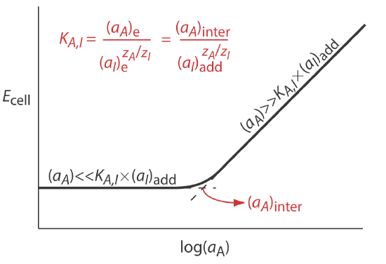
where zA and zI are the charges of the analyte and the interferent, and KA,I is a selectivity coefficient that accounts for the relative response of the interferent. The selectivity coefficient is defined as
\[K_{A,I} = \frac {(a_A)_e} {(a_I)_e^{z_A/z_I}} \label{membrane5} \]
where (aA)e and (aI)e are the activities of analyte and the interferent that yield identical cell potentials. When the selectivity coefficient is 1.00, the membrane responds equally to the analyte and the interferent. A membrane shows good selectivity for the analyte when KA,I is significantly less than 1.00.
Selectivity coefficients for most commercially available ion-selective electrodes are provided by the manufacturer. If the selectivity coefficient is not known, it is easy to determine its value experimentally by preparing a series of solutions, each of which contains the same activity of interferent, (aI)add, but a different activity of analyte. As shown in Figure \(\PageIndex{2}\), a plot of cell potential versus the log of the analyte’s activity has two distinct linear regions. When the analyte’s activity is significantly larger than KA,I \(\times\) (aI)add, the potential is a linear function of log(aA), as given by Equation \ref{membrane3}. If KA,I \(\times\) (aI)add is significantly larger than the analyte’s activity, however, the cell’s potential remains constant. The activity of analyte and interferent at the intersection of these two linear regions is used to calculate KA,I.
Sokalski and co-workers described a method for preparing ion-selective electrodes with significantly improved selectivities [Sokalski, T.; Ceresa, A.; Zwicki, T.; Pretsch, E. J. Am. Chem. Soc. 1997, 119, 11347–11348]. For example, a conventional Pb2+ ISE has a \(\log K_{\text{Pb}^{2+}/\text{Mg}^{2+}}\) of –3.6. If the potential for a solution in which the activity of Pb2+ is \(4.1 \times 10^{-12}\) is identical to that for a solution in which the activity of Mg2+ is 0.01025, what is the value of \(\log K_{\text{Pb}^{2+}/\text{Mg}^{2+}}\) for their ISE?
Solution
Making appropriate substitutions into Equation \ref{membrane5}, we find that
\[K_{\text{Pb}^{2+}/\text{Mg}^{2+}} = \frac {(a_{\text{Pb}^{2+}})_e} {(a_{\text{Mg}^{2+}})_e^{z_{\text{Pb}^{2+}}/z_{\text{Mg}^{2+}}}} = \frac {4.1 \times 10^{-12}} {(0.01025)^{+2/+2}} = 4.0 \times 10^{-10} \nonumber \]
The value of \(\log K_{\text{Pb}^{2+}/\text{Mg}^{2+}}\), therefore, is –9.40.
The Glass Electrode for pH Measurements
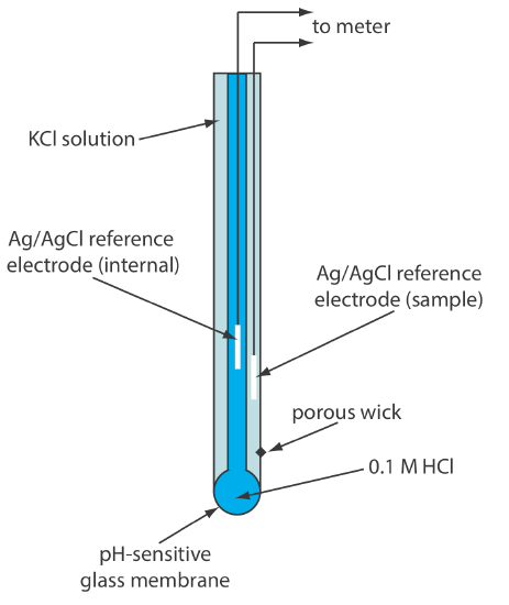
The earliest ion-selective electrodes were based on the observation that a thin glass membrane separating two solutions with different levels of acidity develops a measurable difference in potential on opposite sides of the membrane. Incorporating the glass electrode into a potentiometer along with a reference electrode provides a way to measure the potential. Commercial glass membrane pH electrodes often are available in a combination form that includes both the indicator electrode and the reference electrode. The use of a single electrode greatly simplifies the measurement of pH. An example of a typical combination electrode is shown in Figure \(\PageIndex{3}\).
The Composition and Structure of Glass Membranes
The first commercial glass electrodes were manufactured using Corning 015, a glass with a composition that is approximately 22% Na2O, 6% CaO, and 72% SiO2. Membranes fashioned from Corning 015 have an excellent selectivity for hydrogen ions, H+, below a pH of 9; above this pH the membrane becomes more selective for other cations and the measured pH value deviates from its actual value. Replacing Na2O and CaO with Li2O and BaO extends the useful pH range of glass membranes to pH levels greater than 12.
Origin of the Boundary Potential for a Glass Membrane
When immersed in an aqueous solution for several hours, the outer approximately 10 nm of the glass membrane’s surface becomes hydrated, resulting in the formation of negatively charged sites, —SiO–. Sodium ions, Na+, serve as counter ions. Because H+ binds more strongly to —SiO– than does Na+, they displace the sodium ions on both sides of the membrane.
\[\mathrm{H}^{+}+-\mathrm{SiO}^{-} \mathrm{Na}^{+}\rightleftharpoons-\mathrm{SiO}^{-} \mathrm{H}^{+}+\mathrm{Na}^{+} \label{glass1} \]
explaining the membrane’s selectivity for H+. The transport of charge across the membrane is carried by the Na+ ions within the glass membrane. The potential of a glass electrode obeys the equation
\[E_{\mathrm{cell}}=K+0.05916 \log a_{\mathrm{H}^{+}} \label{glass2} \]
Alkaline and Acid Errors
As noted above, at sufficiently basic pH values a glass electrode no longer provides an accurate measure of a sample's pH as the membrane becomes more selective for other monovalent cations, such as Na+ and K+.
For a Corning 015 glass membrane, the selectivity coefficient KH+/Na+ is \(\approx 10^{-11}\). What is the expected error if we measure the pH of a solution in which the activity of H+ is \(2 \times 10^{-13}\) and the activity of Na+ is 0.05?
Solution
A solution in which the activity of H+, (aH+)act, is \(2 \times 10^{-13}\) has a pH of 12.7. Because the electrode responds to both H+ and Na+, the apparent activity of H+, (aH+)app, is
\[(a_{\text{H}^+})_\text{app} = (a_{\text{H}^+})_\text{act} + (K_{\text{H}^+ / \text{Na}^+} \times a_{\text{Na}^+}) = 2 \times 10^{-13} + (10^{-11} \times 0.05) = 7 \times 10^{-13} \nonumber \]
The apparent activity of H+ is equivalent to a pH of 12.2, an error of –0.5 pH units.
Glass pH electrodes also show deviations from ideal behavior at pH levels less than 0.5, although the reasons for this are not clear. Still, a glass electrode has a wide dynamic range for measuring pH.
Other Limitations to Glass Electrodes
Because an ion-selective electrode’s glass membrane is very thin—it is only about 50 μm thick—they must be handled with care to avoid cracks or breakage. Glass electrodes usually are stored in a storage buffer recommended by the manufacturer, which ensures that the membrane’s outer surface remains hydrated. If a glass electrode dries out, it is reconditioned by soaking for several hours in a solution that contains the analyte. The composition of a glass membrane will change over time, which affects the electrode’s performance. The average lifetime for a typical glass electrode is several years.
Glass Electrodes for Other Cations
The observation that the Corning 015 glass membrane responds to ions other than H+ led to the development of glass membranes with a greater selectivity for other cations. For example, a glass membrane with a composition of 11% Na2O, 18% Al2O3, and 71% SiO2 is used as an ion-selective electrode for Na+. Other glass ion-selective electrodes have been developed for the analysis of Li+, K+, Rb+, Cs+, \(\text{NH}_4^+\), Ag+, and Tl+. Table \(\PageIndex{1}\) provides several examples.
Crystalline Membrane Electrodes
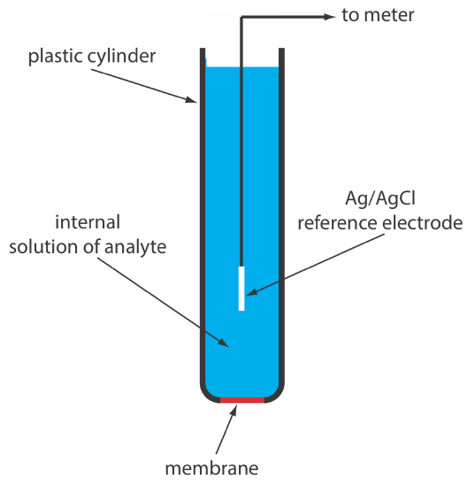
A solid-state ion-selective electrode has a membrane that consists of either a polycrystalline inorganic salt or a single crystal of an inorganic salt. We can fashion a polycrystalline solid-state ion-selective electrode by sealing a 1–2 mm thick pellet of AgS—or a mixture of AgS and a second silver salt or another metal sulfide—into the end of a nonconducting plastic cylinder, filling the cylinder with an internal solution that contains the analyte, and placing a reference electrode into the internal solution. Figure \(\PageIndex{4}\) shows a typical design.
The NaCl in a salt shaker is an example of polycrystalline material because it consists of many small crystals of sodium chloride. The NaCl salt plates used in IR spectroscopy, on the other hand, are an example of a single crystal of sodium chloride.
The membrane potential for a Ag2S pellet develops as the result of a difference in the extent of the solubility reaction
\[\mathrm{Ag}_{2} \mathrm{S}(s)\rightleftharpoons2 \mathrm{Ag}^{+}(a q)+\mathrm{S}^{2-}(a q) \label{ss1} \]
on the membrane’s two sides, with charge carried across the membrane by Ag+ ions. When we use the electrode to monitor the activity of Ag+, the cell potential is
\[E_{\text {cell }}=K+0.05916 \log a_{\mathrm{Ag}^{+}} \label{ss2} \]
The membrane also responds to the activity of \(\text{S}^{2-}\), with a cell potential of
\[E_{\mathrm{cell}}=K-\frac{0.05916}{2} \log a_{\text{S}^{2-}} \label{ss3} \]
If we combine an insoluble silver salt, such as AgCl, with the Ag2S, then the membrane potential also responds to the concentration of Cl–, with a cell potential of
\[E_{\text {cell }}=K-0.05916 \log a_{\mathrm{Cl}^{-}} \label{ss4} \]
By mixing Ag2S with CdS, CuS, or PbS, we can make an ion-selective electrode that responds to the activity of Cd2+, Cu2+, or Pb2+. In this case the cell potential is
\[E_{\mathrm{cell}}=K+\frac{0.05916}{2} \ln a_{M^{2+}} \label{ss5} \]
where aM2+ is the activity of the metal ion.
Table \(\PageIndex{2}\) provides examples of polycrystalline, Ag2S-based solid-state ion-selective electrodes. The selectivity of these ion-selective electrodes depends on the relative solubility of the compounds. A Cl– ISE using a Ag2S/AgCl membrane is more selective for Br– (KCl–/Br– = 102) and for I– (KCl–/I– = 106) because AgBr and AgI are less soluble than AgCl. If the activity of Br– is sufficiently high, AgCl at the membrane/solution interface is replaced by AgBr and the electrode’s response to Cl– decreases substantially. Most of the polycrystalline ion-selective electrodes listed in Table \(\PageIndex{2}\) operate over an extended range of pH levels. The equilibrium between S2– and HS– limits the analysis for S2– to a pH range of 13–14.
The membrane of a F– ion-selective electrode is fashioned from a single crystal of LaF3, which usually is doped with a small amount of EuF2 to enhance the membrane’s conductivity. Because EuF2 provides only two F– ions—compared to the three F– ions in LaF3—each EuF2 produces a vacancy in the crystal’s lattice. Fluoride ions pass through the membrane by moving into adjacent vacancies. As shown in Figure \(\PageIndex{4}\), the LaF3 membrane is sealed into the end of a non-conducting plastic cylinder, which contains a standard solution of F–, typically 0.1 M NaF, and a Ag/AgCl reference electrode.
The membrane potential for a F– ISE results from a difference in the solubility of LaF3 on opposite sides of the membrane, with the potential given by
\[E_{\mathrm{cell}}=K-0.05916 \log a_{\mathrm{F}^-} \label{ss6} \]
One advantage of the F– ion-selective electrode is its freedom from interference. The only significant exception is OH– (KF–/OH– = 0.1), which imposes a maximum pH limit for a successful analysis. Below a pH of 4 the predominate form of fluoride in solution is HF, which does not contribute to the membrane potential. For this reason, an analysis for fluoride is carried out at a pH greater than 4.
What is the maximum pH that we can tolerate if we need to analyze a solution in which the activity of F– is \(1 \times 10^{-5}\) with an error of less than 1%?
Solution
In the presence of OH– the cell potential is
\[E_{\mathrm{cell}}=K-0.05916\left\{a_{\mathrm{F}^-}+K_{\mathrm{F}^- / \mathrm{OH}^{-}} \times a_{\mathrm{OH}^-}\right\} \nonumber \]
To achieve an error of less than 1%, the term \(K_{\mathrm{F}^- / \mathrm{OH}^{-}} \times a_{\mathrm{OH}^-}\) must be less than 1% of aF–; thus
\[K_{\mathrm{F}^- / \mathrm{OH}^-} \times a_{\mathrm{OH}^{-}} \leq 0.01 \times a_{\mathrm{F}^-} \nonumber \]
\[0.10 \times a_{\mathrm{OH}^{-}} \leq 0.01 \times\left(1.0 \times 10^{-5}\right) \nonumber \]
Solving for aOH– gives the maximum allowable activity for OH– as \(1 \times 10^{-6}\), which corresponds to a pH of less than 8.
Unlike a glass membrane ion-selective electrode, a solid-state ISE does not need to be conditioned before it is used, and it may be stored dry. The surface of the electrode is subject to poisoning, as described above for a Cl– ISE in contact with an excessive concentration of Br–. If an electrode is poisoned, it can be returned to its original condition by sanding and polishing the crystalline membrane.
Poisoning simply means that the surface has been chemically modified, such as AgBr forming on the surface of a AgCl membrane.
Liquid Membrane Electrodes
Another class of ion-selective electrodes uses a hydrophobic membrane that contains a liquid organic complexing agent that reacts selectively with the analyte. Three types of organic complexing agents have been used: cation exchangers, anion exchangers, and neutral ionophores. A membrane potential exists if the analyte’s activity is different on the two sides of the membrane. Current is carried through the membrane by the analyte.
An ionophore is a ligand whose exterior is hydrophobic and whose interior is hydrophilic. The crown ether shown here is one example of a neutral ionophore.

One example of a liquid-based ion-selective electrode is that for Ca2+, which uses a porous plastic membrane saturated with the cation exchanger di-(n-decyl) phosphate. As shown in Figure \(\PageIndex{5}\), the membrane is placed at the end of a non-conducting cylindrical tube and is in contact with two reservoirs. The outer reservoir contains di-(n-decyl) phosphate in di-n-octylphenylphosphonate, which soaks into the porous membrane. The inner reservoir contains a standard aqueous solution of Ca2+ and a Ag/AgCl reference electrode. Calcium ion-selective electrodes also are available in which the di-(n-decyl) phosphate is immobilized in a polyvinyl chloride (PVC) membrane that eliminates the need for the outer reservoir.
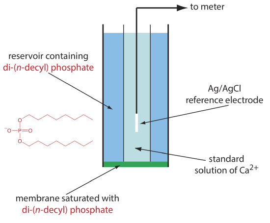
The membrane potential for the Ca2+ ISE develops as the result of a difference in the extent of the complexation reaction
\[\mathrm{Ca}^{2+}(a q)+2\left(\mathrm{C}_{10} \mathrm{H}_{21} \mathrm{O}\right)_{2} \mathrm{PO}_{2}^{-}(mem) \rightleftharpoons \mathrm{Ca}\left[\left(\mathrm{C}_{10} \mathrm{H}_{21} \mathrm{O}\right)_{2} \mathrm{PO}_{2}\right]_2 (mem) \label{liq1} \]
on the two sides of the membrane, where (mem) indicates a species that is present in the membrane. The cell potential for the Ca2+ ion-selective electrode is
\[E_{\mathrm{cell}}=K+\frac{0.05916}{2} \log a_{\mathrm{ca}^{2+}} \label{liq2} \]
The selectivity of this electrode for Ca2+ is very good, with only Zn2+ showing greater selectivity.
Table \(\PageIndex{3}\) lists the properties of several liquid-based ion-selective electrodes. An electrode using a liquid reservoir can be stored in a dilute solution of analyte and needs no additional conditioning before use. The lifetime of an electrode with a PVC membrane, however, is proportional to its exposure to aqueous solutions. For this reason these electrodes are best stored by covering the membrane with a cap along with a small amount of wetted gauze to maintain a humid environment. Before using the electrode it is conditioned in a solution of analyte for 30–60 minutes.


