
23.4: Molecular-Selective Electrode Systems
- Page ID
- 333594

\( \newcommand{\vecs}[1]{\overset { \scriptstyle \rightharpoonup} {\mathbf{#1}} } \)
\( \newcommand{\vecd}[1]{\overset{-\!-\!\rightharpoonup}{\vphantom{a}\smash {#1}}} \)
\( \newcommand{\dsum}{\displaystyle\sum\limits} \)
\( \newcommand{\dint}{\displaystyle\int\limits} \)
\( \newcommand{\dlim}{\displaystyle\lim\limits} \)
\( \newcommand{\id}{\mathrm{id}}\) \( \newcommand{\Span}{\mathrm{span}}\)
( \newcommand{\kernel}{\mathrm{null}\,}\) \( \newcommand{\range}{\mathrm{range}\,}\)
\( \newcommand{\RealPart}{\mathrm{Re}}\) \( \newcommand{\ImaginaryPart}{\mathrm{Im}}\)
\( \newcommand{\Argument}{\mathrm{Arg}}\) \( \newcommand{\norm}[1]{\| #1 \|}\)
\( \newcommand{\inner}[2]{\langle #1, #2 \rangle}\)
\( \newcommand{\Span}{\mathrm{span}}\)
\( \newcommand{\id}{\mathrm{id}}\)
\( \newcommand{\Span}{\mathrm{span}}\)
\( \newcommand{\kernel}{\mathrm{null}\,}\)
\( \newcommand{\range}{\mathrm{range}\,}\)
\( \newcommand{\RealPart}{\mathrm{Re}}\)
\( \newcommand{\ImaginaryPart}{\mathrm{Im}}\)
\( \newcommand{\Argument}{\mathrm{Arg}}\)
\( \newcommand{\norm}[1]{\| #1 \|}\)
\( \newcommand{\inner}[2]{\langle #1, #2 \rangle}\)
\( \newcommand{\Span}{\mathrm{span}}\) \( \newcommand{\AA}{\unicode[.8,0]{x212B}}\)
\( \newcommand{\vectorA}[1]{\vec{#1}} % arrow\)
\( \newcommand{\vectorAt}[1]{\vec{\text{#1}}} % arrow\)
\( \newcommand{\vectorB}[1]{\overset { \scriptstyle \rightharpoonup} {\mathbf{#1}} } \)
\( \newcommand{\vectorC}[1]{\textbf{#1}} \)
\( \newcommand{\vectorD}[1]{\overrightarrow{#1}} \)
\( \newcommand{\vectorDt}[1]{\overrightarrow{\text{#1}}} \)
\( \newcommand{\vectE}[1]{\overset{-\!-\!\rightharpoonup}{\vphantom{a}\smash{\mathbf {#1}}}} \)
\( \newcommand{\vecs}[1]{\overset { \scriptstyle \rightharpoonup} {\mathbf{#1}} } \)
\(\newcommand{\longvect}{\overrightarrow}\)
\( \newcommand{\vecd}[1]{\overset{-\!-\!\rightharpoonup}{\vphantom{a}\smash {#1}}} \)
\(\newcommand{\avec}{\mathbf a}\) \(\newcommand{\bvec}{\mathbf b}\) \(\newcommand{\cvec}{\mathbf c}\) \(\newcommand{\dvec}{\mathbf d}\) \(\newcommand{\dtil}{\widetilde{\mathbf d}}\) \(\newcommand{\evec}{\mathbf e}\) \(\newcommand{\fvec}{\mathbf f}\) \(\newcommand{\nvec}{\mathbf n}\) \(\newcommand{\pvec}{\mathbf p}\) \(\newcommand{\qvec}{\mathbf q}\) \(\newcommand{\svec}{\mathbf s}\) \(\newcommand{\tvec}{\mathbf t}\) \(\newcommand{\uvec}{\mathbf u}\) \(\newcommand{\vvec}{\mathbf v}\) \(\newcommand{\wvec}{\mathbf w}\) \(\newcommand{\xvec}{\mathbf x}\) \(\newcommand{\yvec}{\mathbf y}\) \(\newcommand{\zvec}{\mathbf z}\) \(\newcommand{\rvec}{\mathbf r}\) \(\newcommand{\mvec}{\mathbf m}\) \(\newcommand{\zerovec}{\mathbf 0}\) \(\newcommand{\onevec}{\mathbf 1}\) \(\newcommand{\real}{\mathbb R}\) \(\newcommand{\twovec}[2]{\left[\begin{array}{r}#1 \\ #2 \end{array}\right]}\) \(\newcommand{\ctwovec}[2]{\left[\begin{array}{c}#1 \\ #2 \end{array}\right]}\) \(\newcommand{\threevec}[3]{\left[\begin{array}{r}#1 \\ #2 \\ #3 \end{array}\right]}\) \(\newcommand{\cthreevec}[3]{\left[\begin{array}{c}#1 \\ #2 \\ #3 \end{array}\right]}\) \(\newcommand{\fourvec}[4]{\left[\begin{array}{r}#1 \\ #2 \\ #3 \\ #4 \end{array}\right]}\) \(\newcommand{\cfourvec}[4]{\left[\begin{array}{c}#1 \\ #2 \\ #3 \\ #4 \end{array}\right]}\) \(\newcommand{\fivevec}[5]{\left[\begin{array}{r}#1 \\ #2 \\ #3 \\ #4 \\ #5 \\ \end{array}\right]}\) \(\newcommand{\cfivevec}[5]{\left[\begin{array}{c}#1 \\ #2 \\ #3 \\ #4 \\ #5 \\ \end{array}\right]}\) \(\newcommand{\mattwo}[4]{\left[\begin{array}{rr}#1 \amp #2 \\ #3 \amp #4 \\ \end{array}\right]}\) \(\newcommand{\laspan}[1]{\text{Span}\{#1\}}\) \(\newcommand{\bcal}{\cal B}\) \(\newcommand{\ccal}{\cal C}\) \(\newcommand{\scal}{\cal S}\) \(\newcommand{\wcal}{\cal W}\) \(\newcommand{\ecal}{\cal E}\) \(\newcommand{\coords}[2]{\left\{#1\right\}_{#2}}\) \(\newcommand{\gray}[1]{\color{gray}{#1}}\) \(\newcommand{\lgray}[1]{\color{lightgray}{#1}}\) \(\newcommand{\rank}{\operatorname{rank}}\) \(\newcommand{\row}{\text{Row}}\) \(\newcommand{\col}{\text{Col}}\) \(\renewcommand{\row}{\text{Row}}\) \(\newcommand{\nul}{\text{Nul}}\) \(\newcommand{\var}{\text{Var}}\) \(\newcommand{\corr}{\text{corr}}\) \(\newcommand{\len}[1]{\left|#1\right|}\) \(\newcommand{\bbar}{\overline{\bvec}}\) \(\newcommand{\bhat}{\widehat{\bvec}}\) \(\newcommand{\bperp}{\bvec^\perp}\) \(\newcommand{\xhat}{\widehat{\xvec}}\) \(\newcommand{\vhat}{\widehat{\vvec}}\) \(\newcommand{\uhat}{\widehat{\uvec}}\) \(\newcommand{\what}{\widehat{\wvec}}\) \(\newcommand{\Sighat}{\widehat{\Sigma}}\) \(\newcommand{\lt}{<}\) \(\newcommand{\gt}{>}\) \(\newcommand{\amp}{&}\) \(\definecolor{fillinmathshade}{gray}{0.9}\)The electrodes in Chapter 23.3 are selective toward ions. In this section we consider how we can incorporate an ion-selective electrode into an electrode that responds to neutral species, such as volatile analytes, such as CO2 and NH3, and biochemically important compounds, such as amino acids and urea.
Gas-Sensing Membrane Electrodes
A number of membrane electrodes respond to the concentration of a dissolved gas. The basic design of a gas-sensing electrode, as shown in Figure \(\PageIndex{1}\), consists of a thin membrane that separates the sample from an inner solution that contains an ion-selective electrode. The membrane is permeable to the gaseous analyte, but impermeable to nonvolatile components in the sample’s matrix. The gaseous analyte passes through the membrane where it reacts with the inner solution, producing a species whose concentration is monitored by the ion-selective electrode. For example, in a CO2 electrode, CO2 diffuses across the membrane where it reacts in the inner solution to produce H3O+.
\[\mathrm{CO}_{2}(a q)+2 \mathrm{H}_{2} \mathrm{O}(l)\rightleftharpoons\text{ HCO}_{3}^{-}(a q)+\text{ H}_{3} \mathrm{O}^{+}(a q) \label{gas1} \]
The change in the activity of H3O+ in the inner solution is monitored with a pH electrode, for which the cell potential, from Chapter 23.3, is
\[E_\text{cell} = K + 0.05916 \log a_{\ce{H+}} \label{gas2} \]
To find the relationship between the activity of H3O+ in the inner solution and the activity of CO2 in the inner solution we rearrange the equilibrium constant expression for reaction \ref{gas1}; thus
\[a_{\mathrm{H}_{3} \mathrm{O}^{+}}=K_{\mathrm{a}} \times \frac{a_{\mathrm{CO}_{2}}}{a_{\mathrm{HCO}_{3}^{-}}} \label{gas3} \]
where Ka is the equilibrium constant. If the activity of \(\text{HCO}_3^-\) in the internal solution is sufficiently large, then its activity is not affected by the small amount of CO2 that passes through the membrane. Substituting Equation \ref{gas3} into Equation \ref{gas2} gives
\[E_{\mathrm{cell}}=K^{\prime}+0.05916 \log a_{\mathrm{co}_{2}} \label{gas4} \]
where K′ is a constant that includes the constant for the pH electrode, the equilibrium constant for reaction \ref{gas1} and the activity of \(\text{HCO}_3^-\) in the inner solution.
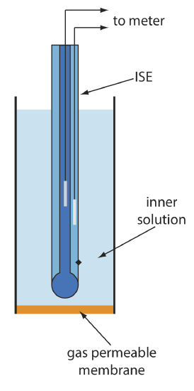
Table \(\PageIndex{1}\) lists the properties of several gas-sensing electrodes. The composition of the inner solution changes with use, and both the inner solution and the membrane must be replaced periodically. Gas-sensing electrodes are stored in a solution similar to the internal solution to minimize their exposure to atmospheric gases.
Biocatalytic Membrane Electrodes
The approach for developing gas-sensing electrodes can be modified to create potentiometric electrodes that respond to a biochemically important species. The most common class of potentiometric biosensors are enzyme electrodes, in which we trap or immobilize an enzyme at the surface of a potentiometric electrode. The analyte’s reaction with the enzyme produces a product whose concentration is monitored by the potentiometric electrode. Potentiometric biosensors also have been designed around other biologically active species, including antibodies, bacterial particles, tissues, and hormone receptors.
One example of an enzyme electrode is the urea electrode, which is based on the catalytic hydrolysis of urea by urease
\[\mathrm{CO}\left(\mathrm{NH}_{2}\right)_{2}(a q)+2 \mathrm{H}_{2} \mathrm{O}(l)\rightleftharpoons 2 \mathrm{NH}_{4}^{+}(a q)+\text{ CO}_{3}^{-}(a q) \label{bio1} \]
Figure \(\PageIndex{2}\) shows one version of the urea electrode, which modifies a gas-sensing NH3 electrode by adding a dialysis membrane that traps a pH 7.0 buffered solution of urease between the dialysis membrane and the gas permeable membrane [(a) Papastathopoulos, D. S.; Rechnitz, G. A. Anal. Chim. Acta 1975, 79, 17–26; (b) Riechel, T. L. J. Chem. Educ. 1984, 61, 640–642]. An NH3 electrode, as shown in Table \(\PageIndex{1}\), uses a gas-permeable membrane and a glass pH electrode. The NH3 diffuses across the membrane where it changes the pH of the internal solution.
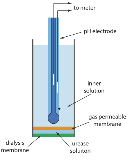
When immersed in the sample, urea diffuses through the dialysis membrane where it reacts with the enzyme urease to form the ammonium ion, \(\text{NH}_4^+\), which is in equilibrium with NH3.
\[\mathrm{NH}_{4}^{+}(a q)+\mathrm{H}_{2} \mathrm{O}(l ) \rightleftharpoons \text{ H}_{3} \mathrm{O}^{+}(a q)+\text{ NH}_{3}(a q) \label{bio2} \]
The NH3, in turn, diffuses through the gas permeable membrane where a pH electrode measures the resulting change in pH. The electrode’s response to the concentration of urea is
\[E_{\text {cell }}=K-0.05916 \log a_{\text {urea }} \label{bio3} \]
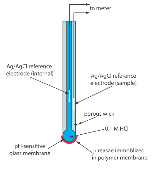
Another version of the urea electrode (Figure \(\PageIndex{3}\)) immobilizes the enzyme urease in a polymer membrane formed directly on the tip of a glass pH electrode [Tor, R.; Freeman, A. Anal. Chem. 1986, 58, 1042–1046]. In this case the response of the electrode is
\[\mathrm{pH}=K a_{\mathrm{urea}} \label{bio4} \]
Few potentiometric biosensors are available commercially. As shown in Figure \(\PageIndex{2}\) and Figure \(\PageIndex{3}\), however, it is possible to convert an ion-selective electrode or a gas-sensing electrode into a biosensor. Several representative examples are described in Table \(\PageIndex{2}\), and additional examples can be found in this chapter’s additional resources.
| analyte | biologically active phase | substance determined |
|---|---|---|
| \(5^{\prime}\)-AMP | AMP-deaminase (E) | NH3 |
| L-arginine | arginine and urease (E) | NH3 |
| asparagine | asparaginase (E) | \(\text{NH}_4^+\) |
| L-cysteine | Proteus morganii (B) | H2S |
| L-glutamate | yellow squash (T) | CO2 |
| L-glutamine | Sarcina flava (B) | NH3 |
| oxalate | oxalate decarboxylase (E) | CO2 |
| penicillin | penicllinase (E) | H3O+ |
| L-phenylalanine | L-amino acid oxidase/horseradish peroxidase (E) | I– |
| sugars | bacteria from dental plaque (B) | H3O+ |
| urea | urease (E) | NH3 or H3O+ |
|
Source: Complied from Cammann, K. Working With Ion-Selective Electrodes, Springer-Verlag: Berlin, 1977 and Lunte, C. E.; Heineman, W. R. “Electrochemical techniques in Bioanalysis,” in Steckham, E. ed. Topics in Current Chemistry, Vol. 143, Springer-Verlag: Berlin, 1988, p.8. Abbreviations for biologically active phase: E = enzyme; B = bacterial particle; T = tissue. |
||