3.3.8: Geometry and Orbital Contribution
- Page ID
- 202275
\( \newcommand{\vecs}[1]{\overset { \scriptstyle \rightharpoonup} {\mathbf{#1}} } \)
\( \newcommand{\vecd}[1]{\overset{-\!-\!\rightharpoonup}{\vphantom{a}\smash {#1}}} \)
\( \newcommand{\id}{\mathrm{id}}\) \( \newcommand{\Span}{\mathrm{span}}\)
( \newcommand{\kernel}{\mathrm{null}\,}\) \( \newcommand{\range}{\mathrm{range}\,}\)
\( \newcommand{\RealPart}{\mathrm{Re}}\) \( \newcommand{\ImaginaryPart}{\mathrm{Im}}\)
\( \newcommand{\Argument}{\mathrm{Arg}}\) \( \newcommand{\norm}[1]{\| #1 \|}\)
\( \newcommand{\inner}[2]{\langle #1, #2 \rangle}\)
\( \newcommand{\Span}{\mathrm{span}}\)
\( \newcommand{\id}{\mathrm{id}}\)
\( \newcommand{\Span}{\mathrm{span}}\)
\( \newcommand{\kernel}{\mathrm{null}\,}\)
\( \newcommand{\range}{\mathrm{range}\,}\)
\( \newcommand{\RealPart}{\mathrm{Re}}\)
\( \newcommand{\ImaginaryPart}{\mathrm{Im}}\)
\( \newcommand{\Argument}{\mathrm{Arg}}\)
\( \newcommand{\norm}[1]{\| #1 \|}\)
\( \newcommand{\inner}[2]{\langle #1, #2 \rangle}\)
\( \newcommand{\Span}{\mathrm{span}}\) \( \newcommand{\AA}{\unicode[.8,0]{x212B}}\)
\( \newcommand{\vectorA}[1]{\vec{#1}} % arrow\)
\( \newcommand{\vectorAt}[1]{\vec{\text{#1}}} % arrow\)
\( \newcommand{\vectorB}[1]{\overset { \scriptstyle \rightharpoonup} {\mathbf{#1}} } \)
\( \newcommand{\vectorC}[1]{\textbf{#1}} \)
\( \newcommand{\vectorD}[1]{\overrightarrow{#1}} \)
\( \newcommand{\vectorDt}[1]{\overrightarrow{\text{#1}}} \)
\( \newcommand{\vectE}[1]{\overset{-\!-\!\rightharpoonup}{\vphantom{a}\smash{\mathbf {#1}}}} \)
\( \newcommand{\vecs}[1]{\overset { \scriptstyle \rightharpoonup} {\mathbf{#1}} } \)
\( \newcommand{\vecd}[1]{\overset{-\!-\!\rightharpoonup}{\vphantom{a}\smash {#1}}} \)
\(\newcommand{\avec}{\mathbf a}\) \(\newcommand{\bvec}{\mathbf b}\) \(\newcommand{\cvec}{\mathbf c}\) \(\newcommand{\dvec}{\mathbf d}\) \(\newcommand{\dtil}{\widetilde{\mathbf d}}\) \(\newcommand{\evec}{\mathbf e}\) \(\newcommand{\fvec}{\mathbf f}\) \(\newcommand{\nvec}{\mathbf n}\) \(\newcommand{\pvec}{\mathbf p}\) \(\newcommand{\qvec}{\mathbf q}\) \(\newcommand{\svec}{\mathbf s}\) \(\newcommand{\tvec}{\mathbf t}\) \(\newcommand{\uvec}{\mathbf u}\) \(\newcommand{\vvec}{\mathbf v}\) \(\newcommand{\wvec}{\mathbf w}\) \(\newcommand{\xvec}{\mathbf x}\) \(\newcommand{\yvec}{\mathbf y}\) \(\newcommand{\zvec}{\mathbf z}\) \(\newcommand{\rvec}{\mathbf r}\) \(\newcommand{\mvec}{\mathbf m}\) \(\newcommand{\zerovec}{\mathbf 0}\) \(\newcommand{\onevec}{\mathbf 1}\) \(\newcommand{\real}{\mathbb R}\) \(\newcommand{\twovec}[2]{\left[\begin{array}{r}#1 \\ #2 \end{array}\right]}\) \(\newcommand{\ctwovec}[2]{\left[\begin{array}{c}#1 \\ #2 \end{array}\right]}\) \(\newcommand{\threevec}[3]{\left[\begin{array}{r}#1 \\ #2 \\ #3 \end{array}\right]}\) \(\newcommand{\cthreevec}[3]{\left[\begin{array}{c}#1 \\ #2 \\ #3 \end{array}\right]}\) \(\newcommand{\fourvec}[4]{\left[\begin{array}{r}#1 \\ #2 \\ #3 \\ #4 \end{array}\right]}\) \(\newcommand{\cfourvec}[4]{\left[\begin{array}{c}#1 \\ #2 \\ #3 \\ #4 \end{array}\right]}\) \(\newcommand{\fivevec}[5]{\left[\begin{array}{r}#1 \\ #2 \\ #3 \\ #4 \\ #5 \\ \end{array}\right]}\) \(\newcommand{\cfivevec}[5]{\left[\begin{array}{c}#1 \\ #2 \\ #3 \\ #4 \\ #5 \\ \end{array}\right]}\) \(\newcommand{\mattwo}[4]{\left[\begin{array}{rr}#1 \amp #2 \\ #3 \amp #4 \\ \end{array}\right]}\) \(\newcommand{\laspan}[1]{\text{Span}\{#1\}}\) \(\newcommand{\bcal}{\cal B}\) \(\newcommand{\ccal}{\cal C}\) \(\newcommand{\scal}{\cal S}\) \(\newcommand{\wcal}{\cal W}\) \(\newcommand{\ecal}{\cal E}\) \(\newcommand{\coords}[2]{\left\{#1\right\}_{#2}}\) \(\newcommand{\gray}[1]{\color{gray}{#1}}\) \(\newcommand{\lgray}[1]{\color{lightgray}{#1}}\) \(\newcommand{\rank}{\operatorname{rank}}\) \(\newcommand{\row}{\text{Row}}\) \(\newcommand{\col}{\text{Col}}\) \(\renewcommand{\row}{\text{Row}}\) \(\newcommand{\nul}{\text{Nul}}\) \(\newcommand{\var}{\text{Var}}\) \(\newcommand{\corr}{\text{corr}}\) \(\newcommand{\len}[1]{\left|#1\right|}\) \(\newcommand{\bbar}{\overline{\bvec}}\) \(\newcommand{\bhat}{\widehat{\bvec}}\) \(\newcommand{\bperp}{\bvec^\perp}\) \(\newcommand{\xhat}{\widehat{\xvec}}\) \(\newcommand{\vhat}{\widehat{\vvec}}\) \(\newcommand{\uhat}{\widehat{\uvec}}\) \(\newcommand{\what}{\widehat{\wvec}}\) \(\newcommand{\Sighat}{\widehat{\Sigma}}\) \(\newcommand{\lt}{<}\) \(\newcommand{\gt}{>}\) \(\newcommand{\amp}{&}\) \(\definecolor{fillinmathshade}{gray}{0.9}\)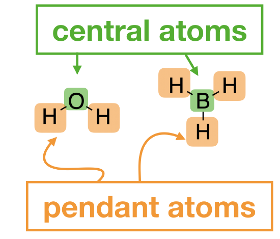 What if a molecule had three or more atoms in it? In the case of polyatomic molecules, we can no longer draw a simple molecular orbital interaction diagram in which we show one atom on each side and the molecular results in the middle, because we don't have two atoms coming together to share electrons.
In the case of metal ions, we usually have a metal ion in the center surrounded by several ligands. Ligands can be simplified if we consider only the atom directly bound to the metal ion; we call these "pendant" atoms. The approach to drawing a polyatomic MO diagram for a metal ion complex changes only slightly compared to what you’ve done before with diatomic molecules. The main difference now is that the orbitals on pendant atoms are treated as a set that is fixed in space with respect to the central atom. Each set of orbitals takes on its own symmetry identity. MOs form when the symmetry of the set of pendant atoms is compatible with one or more atomic orbitals on the central atom.
Let's start with some simple examples. At a very simple level, the qualitative result is always the same and can be roughly predicted based on the Lewis structure.
Useful predictions about MO's based on the Lewis Structure:
- There is a bonding MO for every bond you see in the Lewis structure. These levels are low on the diagram.
- Every bonding MO has a corresponding antibonding MO. These levels are high on the diagram.
- Lone pairs in Lewis structure correspond to non-bonding orbitals. These levels are intermediate on the diagram.
- The diagram is populated by the same number of electrons that you see in the Lewis structure.
Example 1: Methane
Methane is a moderately small molecule. Its Lewis structure is pretty easy to draw, with a carbon in the middle bonded to four hydrogens. Trying to find the interactions of the hydrogen 1s orbital with the orbitals on carbon could be challenging. However, molecular orbital calculations generally start with a good guess at the geometry of the structure.
In quantitative calculations, that starting geometry is often modified after the energy of the molecule has been calculated. A long series of iterative calculations are done, changing bond lengths or bond angles each time, until the geometry with the lowest possible energy has been found. If this geometry has the lowest energy, then it is probably the shape that the molecule would really adopt in nature. In fact, it is assumed in quantum chemistry that if a lower energy structure can be found, it is always a more accurate picture of the real molecule (assuming no mistakes have been made in the calculation).
Since the carbon in methane has four groups attached to it, we can be pretty sure that the carbon is tetrahedral.
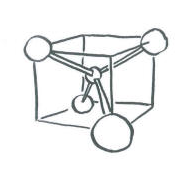
We will assume the four hydrogens are arranged at the corners of a tetrahedron around the central carbon. Overlap with the carbon 2s orbital is easy to see, because the s orbital can overlap with neighbors in all directions. Of course, there could be an in-phase combination and an out-of-phase combination.
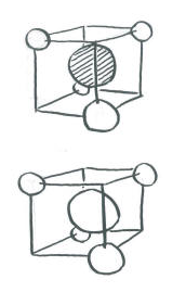
The complicated part arises when we want to introduce the carbon electrons and have them interact with the hydrogens. There is no universal orientation of p orbitals. Which way should they point?
In principle, it does not matter too much what direction we choose for the p orbitals. We should eventually end up with the same conclusions in the end. However, things may get extremely complicated and mistakes are likely to occur if we don't choose an orientation that makes the interactions simple to see. Since it does not matter which way the p orbitals are pointing, we should choose a direction that makes the calculation easiest.
- In a tetrahedron, the four corners point to alternating corners of a cube.
- The hydrogen atoms are in alternating corners of an imaginary cube around the carbon atom.
- The simplest way to align the p orbitals is to have them pointing at the faces of the cube.
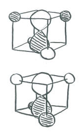
Orienting the p orbitals this way simplifies things a lot. It means each lobe of each p orbital is directed at a space (on the face of a cube) in between two hydrogen atoms (on the opposite corners of the face). The other lobe of the same p orbital is directed at a space (on the opposite face of the cube) in between the other two hydrogen atoms (on the opposite corners of that face). The same is true for each p orbital, but they point at different faces and they interact with different combinations of the same four hydrogens.
As a result of this choice, there are really only a few interactions to consider in methane.
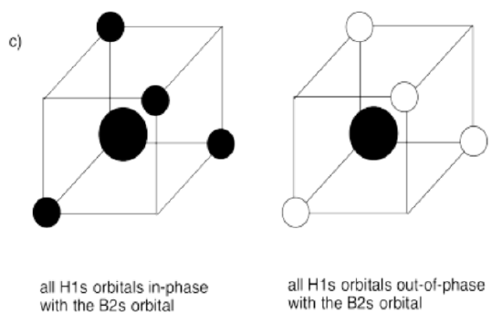
- The carbon 2s orbital can be either in-phase or out-of-phase with the entire group of hydrogen orbitals. That makes two combinations.
- The carbon 2p orbitals can be either in-phase or out-of-phase with their adjacent hydrogen atoms. With three p orbitals, that makes six more combinations.
- Eight atomic orbitals combine to make eight molecular orbital combinations.
Note that here the hydrogen atoms are often treated as being in-phase with each other, or at least pairs of them are. This assumption simplifies the calculation and cuts down on the number of non-allowed combinations (i.e. combinations that produce the total number of orbitals over eight).
Organizing these combinations in terms of energy:
- The carbon 2s + H in-phase combination is entirely bonding. It is very low in energy.
- The carbon 2s - H out-of-phase combination is entirely antibonding. It is very high in energy.
- The carbon 2p + H in-phase combinations are mostly bonding. However, there is a node through the middle of the molecule owing to the node in the p orbital. As a result, the two hydrogens adjacent to one lobe are out of phase with the two hydrogens on the other. This combination is medium-low in energy.
- The carbon 2p - H out-of-phase combinations is highly antibonding. There is a node through the middle of the molecule owing to the node in the p orbital. There are also nodes between the p orbitals and the hydrogen s orbitals. This orbital has the most nodes through the structure and therefore corresponds to the shortest wavelength and highest energy.
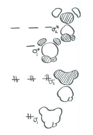
In general, this idea that the geometry around an atom determines what atomic orbitals are needed to form direct (sigma) bonds with its neighbors is closely tied to hybridization. That's the idea that s and p orbitals in the same shell will need to work together to bond to neighboring atoms. In molecules, we sometimes blur the distinction between the ones that are needed to form this set of bonds, and refer to them instead as "hybrids." Hybridization is closely tied to the geometry of the central atom, so much so that the terms, geometry and hybridization, are occasionally used interchangeably.
- linear geometry corresponds to sp hybridization
- trigonal planar geometry corresponds to sp2 hybridization
- tetrahedral geometry corresponds to sp3 hybridization
Construct a molecular orbital picture for borohydride anion, BH4-.
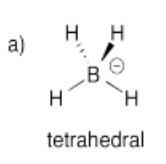
a) Use the geometry for BH4- that you would predict from its Lewis structure.
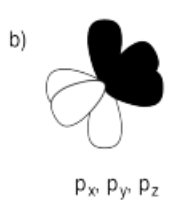
b) Select an orientation for the p orbitals on boron.
c) What interaction are possible between the set of hydrogens and the boron 2s orbital?
d) What interactions are possible between the set of hydrogens and one boron 2p orbital?
e) What interactions are possible between the set of hydrogens and the second boron 2p orbital?
f) What interactions are possible between the set of hydrogens and the third boron 2p orbital?
g) Can all the hydrogen orbitals interact in each case? If not, why not?
h) Order the resulting combinations in energy, show the resulting energy levels and populate them with the correct number of electrons.
- Answer a):
-
- Answer b):
-
- Answer c):
-
- Answer d):
-
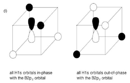
- Answer e):
-
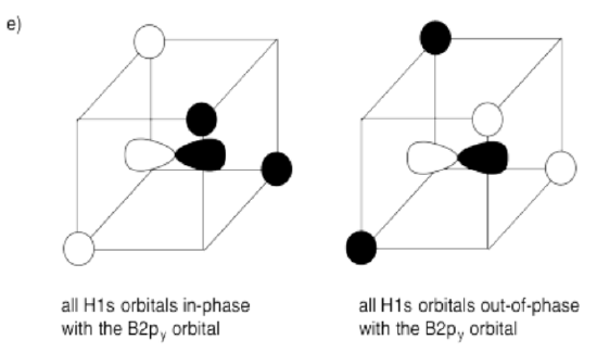
- Answer f):
-
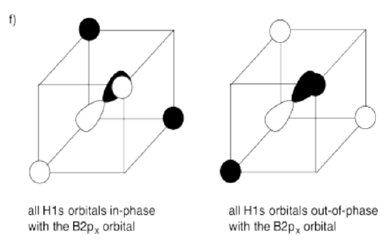
- Answer g):
-

- Answer h):
-
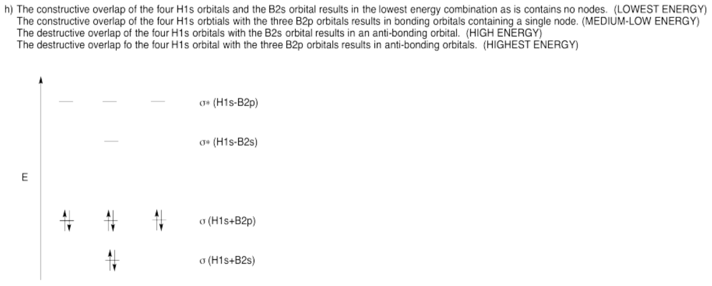
Construct a molecular orbital picture for borane, BH3.
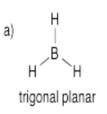
a) Use the geometry for BH3 that you would predict from its Lewis structure.
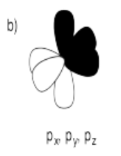
b) Select an orientation for the p orbitals on boron.
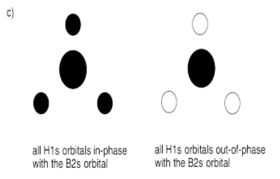
c) What interaction are possible between the set of hydrogens and the boron 2s orbital?
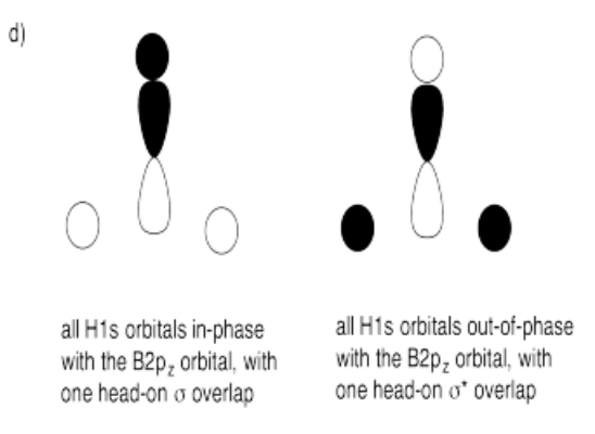
d) What interactions are possible between the set of hydrogens and one boron 2p orbital?
e) What interactions are possible between the set of hydrogens and the second boron 2p orbital?
f) What interactions are possible between the set of hydrogens and the third boron 2p orbital?
g) Can all the hydrogen orbitals interact in each case? If not, why not?
h) Order the resulting combinations in energy, show the resulting energy levels and populate them with the correct number of electrons.
- Answer a):
-
- Answer b):
-
- Answer c):
-
- Answer d):
-
- Answer e):
-
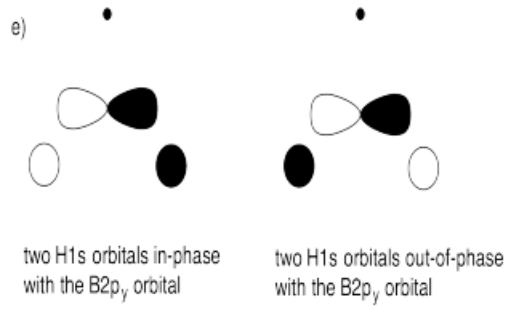
- Answer f):
-
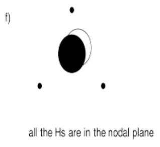
- Answer g):
-

- Answer h):
-
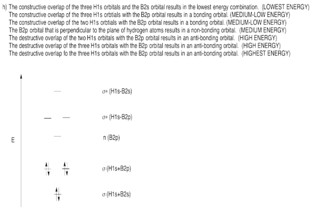
Based upon your results of the previous two questions about borane and borohydride, comment on the energetics involved in the addition of a hydride ion (H-) to borane to produce borohydride. For this question, just assume the hydride electrons start out at a similar energy to the 2p electrons of boron
Construct a molecular orbital picture for carbene, CH2, in two different ways.
a) In one approach, assume the H-C-H forms a 180 degree angle (linear geometry). Only one of the p orbitals lies along this line.
b) In a second approach, assume the H-C-H form a 120 degree angle (angular geometry). These three atoms define a plane. Two of the p orbitals can lie in the plane of these three atoms.
c) Based on your molecular orbital energy level diagrams, which of these two possibilities do you think is most favorable?

