6.2.6: Diffraction
- Page ID
- 220531
\( \newcommand{\vecs}[1]{\overset { \scriptstyle \rightharpoonup} {\mathbf{#1}} } \)
\( \newcommand{\vecd}[1]{\overset{-\!-\!\rightharpoonup}{\vphantom{a}\smash {#1}}} \)
\( \newcommand{\id}{\mathrm{id}}\) \( \newcommand{\Span}{\mathrm{span}}\)
( \newcommand{\kernel}{\mathrm{null}\,}\) \( \newcommand{\range}{\mathrm{range}\,}\)
\( \newcommand{\RealPart}{\mathrm{Re}}\) \( \newcommand{\ImaginaryPart}{\mathrm{Im}}\)
\( \newcommand{\Argument}{\mathrm{Arg}}\) \( \newcommand{\norm}[1]{\| #1 \|}\)
\( \newcommand{\inner}[2]{\langle #1, #2 \rangle}\)
\( \newcommand{\Span}{\mathrm{span}}\)
\( \newcommand{\id}{\mathrm{id}}\)
\( \newcommand{\Span}{\mathrm{span}}\)
\( \newcommand{\kernel}{\mathrm{null}\,}\)
\( \newcommand{\range}{\mathrm{range}\,}\)
\( \newcommand{\RealPart}{\mathrm{Re}}\)
\( \newcommand{\ImaginaryPart}{\mathrm{Im}}\)
\( \newcommand{\Argument}{\mathrm{Arg}}\)
\( \newcommand{\norm}[1]{\| #1 \|}\)
\( \newcommand{\inner}[2]{\langle #1, #2 \rangle}\)
\( \newcommand{\Span}{\mathrm{span}}\) \( \newcommand{\AA}{\unicode[.8,0]{x212B}}\)
\( \newcommand{\vectorA}[1]{\vec{#1}} % arrow\)
\( \newcommand{\vectorAt}[1]{\vec{\text{#1}}} % arrow\)
\( \newcommand{\vectorB}[1]{\overset { \scriptstyle \rightharpoonup} {\mathbf{#1}} } \)
\( \newcommand{\vectorC}[1]{\textbf{#1}} \)
\( \newcommand{\vectorD}[1]{\overrightarrow{#1}} \)
\( \newcommand{\vectorDt}[1]{\overrightarrow{\text{#1}}} \)
\( \newcommand{\vectE}[1]{\overset{-\!-\!\rightharpoonup}{\vphantom{a}\smash{\mathbf {#1}}}} \)
\( \newcommand{\vecs}[1]{\overset { \scriptstyle \rightharpoonup} {\mathbf{#1}} } \)
\( \newcommand{\vecd}[1]{\overset{-\!-\!\rightharpoonup}{\vphantom{a}\smash {#1}}} \)
\(\newcommand{\avec}{\mathbf a}\) \(\newcommand{\bvec}{\mathbf b}\) \(\newcommand{\cvec}{\mathbf c}\) \(\newcommand{\dvec}{\mathbf d}\) \(\newcommand{\dtil}{\widetilde{\mathbf d}}\) \(\newcommand{\evec}{\mathbf e}\) \(\newcommand{\fvec}{\mathbf f}\) \(\newcommand{\nvec}{\mathbf n}\) \(\newcommand{\pvec}{\mathbf p}\) \(\newcommand{\qvec}{\mathbf q}\) \(\newcommand{\svec}{\mathbf s}\) \(\newcommand{\tvec}{\mathbf t}\) \(\newcommand{\uvec}{\mathbf u}\) \(\newcommand{\vvec}{\mathbf v}\) \(\newcommand{\wvec}{\mathbf w}\) \(\newcommand{\xvec}{\mathbf x}\) \(\newcommand{\yvec}{\mathbf y}\) \(\newcommand{\zvec}{\mathbf z}\) \(\newcommand{\rvec}{\mathbf r}\) \(\newcommand{\mvec}{\mathbf m}\) \(\newcommand{\zerovec}{\mathbf 0}\) \(\newcommand{\onevec}{\mathbf 1}\) \(\newcommand{\real}{\mathbb R}\) \(\newcommand{\twovec}[2]{\left[\begin{array}{r}#1 \\ #2 \end{array}\right]}\) \(\newcommand{\ctwovec}[2]{\left[\begin{array}{c}#1 \\ #2 \end{array}\right]}\) \(\newcommand{\threevec}[3]{\left[\begin{array}{r}#1 \\ #2 \\ #3 \end{array}\right]}\) \(\newcommand{\cthreevec}[3]{\left[\begin{array}{c}#1 \\ #2 \\ #3 \end{array}\right]}\) \(\newcommand{\fourvec}[4]{\left[\begin{array}{r}#1 \\ #2 \\ #3 \\ #4 \end{array}\right]}\) \(\newcommand{\cfourvec}[4]{\left[\begin{array}{c}#1 \\ #2 \\ #3 \\ #4 \end{array}\right]}\) \(\newcommand{\fivevec}[5]{\left[\begin{array}{r}#1 \\ #2 \\ #3 \\ #4 \\ #5 \\ \end{array}\right]}\) \(\newcommand{\cfivevec}[5]{\left[\begin{array}{c}#1 \\ #2 \\ #3 \\ #4 \\ #5 \\ \end{array}\right]}\) \(\newcommand{\mattwo}[4]{\left[\begin{array}{rr}#1 \amp #2 \\ #3 \amp #4 \\ \end{array}\right]}\) \(\newcommand{\laspan}[1]{\text{Span}\{#1\}}\) \(\newcommand{\bcal}{\cal B}\) \(\newcommand{\ccal}{\cal C}\) \(\newcommand{\scal}{\cal S}\) \(\newcommand{\wcal}{\cal W}\) \(\newcommand{\ecal}{\cal E}\) \(\newcommand{\coords}[2]{\left\{#1\right\}_{#2}}\) \(\newcommand{\gray}[1]{\color{gray}{#1}}\) \(\newcommand{\lgray}[1]{\color{lightgray}{#1}}\) \(\newcommand{\rank}{\operatorname{rank}}\) \(\newcommand{\row}{\text{Row}}\) \(\newcommand{\col}{\text{Col}}\) \(\renewcommand{\row}{\text{Row}}\) \(\newcommand{\nul}{\text{Nul}}\) \(\newcommand{\var}{\text{Var}}\) \(\newcommand{\corr}{\text{corr}}\) \(\newcommand{\len}[1]{\left|#1\right|}\) \(\newcommand{\bbar}{\overline{\bvec}}\) \(\newcommand{\bhat}{\widehat{\bvec}}\) \(\newcommand{\bperp}{\bvec^\perp}\) \(\newcommand{\xhat}{\widehat{\xvec}}\) \(\newcommand{\vhat}{\widehat{\vvec}}\) \(\newcommand{\uhat}{\widehat{\uvec}}\) \(\newcommand{\what}{\widehat{\wvec}}\) \(\newcommand{\Sighat}{\widehat{\Sigma}}\) \(\newcommand{\lt}{<}\) \(\newcommand{\gt}{>}\) \(\newcommand{\amp}{&}\) \(\definecolor{fillinmathshade}{gray}{0.9}\)learning objectives
- Understanding diffraction
Overview
The Huygens-Fresnel principle states that every point on a wavefront is a source of wavelets. These wavelets spread out in the forward direction, at the same speed as the source wave. The new wavefront is a line tangent to all of the wavelets.
Background
Christiaan Huygens was a Dutch scientist who developed a useful technique for determining how and where waves propagate. In 1678, he proposed that every point that a luminous disturbance touches becomes itself a source of a spherical wave. The sum of the secondary waves (waves that are a result of the disturbance) determines the form of the new wave. shows secondary waves traveling forward from their point of origin. He was able to come up with an explanation of the linear and spherical wave propagation, and derive the laws of reflection and refraction (covered in previous atoms ) using this principle. He could not, however, explain what is commonly known as diffraction effects. Diffraction effects are the deviations from rectilinear propagation that occurs when light encounters edges, screens and apertures. These effects were explained in 1816 by French physicist Augustin-Jean Fresnel.
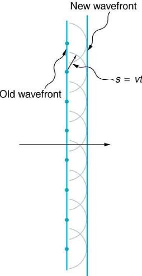
Straight Wavefront: Huygens’s principle applied to a straight wavefront. Each point on the wavefront emits a semicircular wavelet that moves a distance s=vt. The new wavefront is a line tangent to the wavelets.
Huygens’s Principle
Figure 1 shows a simple example of the Huygens’s Principle of diffraction. The principle can be shown with the equation below:
\[\mathrm { s } = \mathrm { v } \mathrm { t }\]
where s is the distance, v is the propagation speed, and t is time.
Each point on the wavefront emits a wave at speed, v. The emitted waves are semicircular, and occur at t, time later. The new wavefront is tangent to the wavelets. This principle works for all wave types, not just light waves. The principle is helpful in describing reflection, refraction and interference. shows visually how Huygens’s Principle can be used to explain reflection, and shows how it can be applied to refraction.
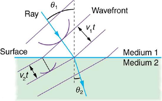
Huygens’s Refraction: Huygens’s principle applied to a straight wavefront traveling from one medium to another where its speed is less. The ray bends toward the perpendicular, since the wavelets have a lower speed in the second medium.
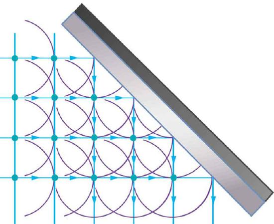
Reflection: Huygens’s principle applied to a straight wavefront striking a mirror. The wavelets shown were emitted as each point on the wavefront struck the mirror. The tangent to these wavelets shows that the new wavefront has been reflected at an angle equal to the incident angle. The direction of propagation is perpendicular to the wavefront, as shown by the downward-pointing arrows.
Example \(\PageIndex{1}\):
This principle is actually something you have seen or experienced often, but just don’t realize. Although this principle applies to all types of waves, it is easier to explain using sound waves, since sound waves have longer wavelengths. If someone is playing music in their room, with the door closed, you might not be able to hear it while walking past the room. However, if that person where to open their door while playing music, you could hear it not only when directly in front of the door opening, but also on a considerable distance down the hall to either side. is a direct effect of diffraction. When light passes through much smaller openings, called slits, Huygens’s principle shows that light bends similar to the way sound does, just on a much smaller scale. We will examine in later atoms single slit diffraction and double slit diffraction, but for now it is just important that we understand the basic concept of diffraction.
Diffraction
As we explained in the previous paragraph, diffraction is defined as the bending of a wave around the edges of an opening or an obstacle.
Young’s Double Slit Experiment
The double-slit experiment, also called Young’s experiment, shows that matter and energy can display both wave and particle characteristics.
learning objectives
- Explain why Young’s experiment more credible than Huygens’
The double-slit experiment, also called Young’s experiment, shows that matter and energy can display both wave and particle characteristics. As we discussed in the atom about the Huygens principle, Christiaan Huygens proved in 1628 that light was a wave. But some people disagreed with him, most notably Isaac Newton. Newton felt that color, interference, and diffraction effects needed a better explanation. People did not accept the theory that light was a wave until 1801, when English physicist Thomas Young performed his double-slit experiment. In his experiment, he sent light through two closely spaced vertical slits and observed the resulting pattern on the wall behind them. The pattern that resulted can be seen in.
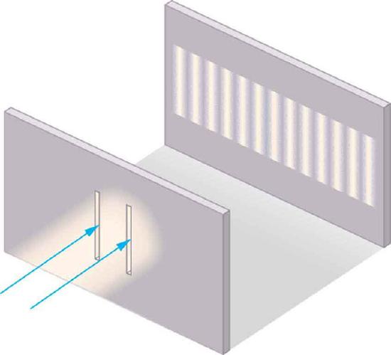
Young’s Double Slit Experiment: Light is sent through two vertical slits and is diffracted into a pattern of vertical lines spread out horizontally. Without diffraction and interference, the light would simply make two lines on the screen.
Wave-Particle Duality
The wave characteristics of light cause the light to pass through the slits and interfere with itself, producing the light and dark areas on the wall behind the slits. The light that appears on the wall behind the slits is scattered and absorbed by the wall, which is a characteristic of a particle.
Young’s Experiment
Why was Young’s experiment so much more credible than Huygens’? Because, while Huygens’ was correct, he could not demonstrate that light acted as a wave, while the double-slit experiment shows this very clearly. Since light has relatively short wavelengths, to show wave effects it must interact with something small — Young’s small, closely spaced slits worked.
The example in uses two coherent light sources of a single monochromatic wavelength for simplicity. (This means that the light sources were in the same phase. ) The two slits cause the two coherent light sources to interfere with each other either constructively or destructively.
Constructive and Destructive Wave Interference
Constructive wave interference occurs when waves interfere with each other crest-to-crest (peak-to-peak) or trough-to-trough (valley-to-valley) and the waves are exactly in phase with each other. This amplifies the resultant wave. Destructive wave interference occurs when waves interfere with each other crest-to-trough (peak-to-valley) and are exactly out of phase with each other. This cancels out any wave and results in no light. These concepts are shown in. It should be noted that this example uses a single, monochromatic wavelength, which is not common in real life; a more practical example is shown in.
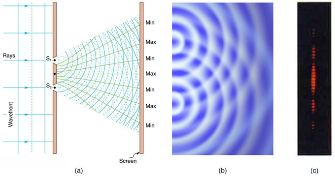
Practical Constructive and Destructive Wave Interference: Double slits produce two coherent sources of waves that interfere. (a) Light spreads out (diffracts) from each slit because the slits are narrow. These waves overlap and interfere constructively (bright lines) and destructively (dark regions). We can only see this if the light falls onto a screen and is scattered into our eyes. (b) Double-slit interference pattern for water waves are nearly identical to that for light. Wave action is greatest in regions of constructive interference and least in regions of destructive interference. (c) When light that has passed through double slits falls on a screen, we see a pattern such as this.
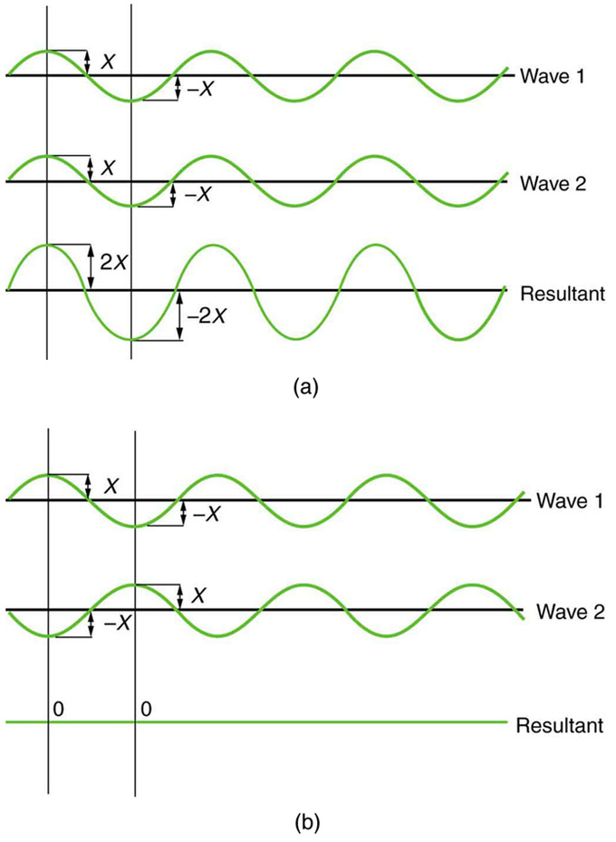
Theoretical Constructive and Destructive Wave Interference: The amplitudes of waves add together. (a) Pure constructive interference is obtained when identical waves are in phase. (b) Pure destructive interference occurs when identical waves are exactly out of phase (shifted by half a wavelength).
The pattern that results from double-slit diffraction is not random, although it may seem that way. Each slit is a different distance from a given point on the wall behind it. For each different distance, a different number of wavelengths fit into that path. The waves all start out in phase (matching crest-to-crest), but depending on the distance of the point on the wall from the slit, they could be in phase at that point and interfere constructively, or they could end up out of phase and interfere with each other destructively.
Diffraction Gratings: X-Ray, Grating, Reflection
Diffraction grating has periodic structure that splits and diffracts light into several beams travelling in different directions.
learning objectives
- Describe function of the diffraction grating
Diffraction Grating
A diffraction grating is an optical component with a periodic structure that splits and diffracts light into several beams travelling in different directions. The directions of these beams depend on the spacing of the grating and the wavelength of the light so that the grating acts as the dispersive element. Because of this, gratings are often used in monochromators, spectrometers, wavelength division multiplexing devices, optical pulse compressing devices, and many other optical instruments.
A photographic slide with a fine pattern of purple lines forms a complex grating. For practical applications, gratings generally have ridges or rulings on their surface rather than dark lines. Such gratings can be either transmissive or reflective. Gratings which modulate the phase rather than the amplitude of the incident light are also produced, frequently using holography.
Ordinary pressed CD and DVD media are every-day examples of diffraction gratings and can be used to demonstrate the effect by reflecting sunlight off them onto a white wall. (see ). This is a side effect of their manufacture, as one surface of a CD has many small pits in the plastic, arranged in a spiral; that surface has a thin layer of metal applied to make the pits more visible. The structure of a DVD is optically similar, although it may have more than one pitted surface, and all pitted surfaces are inside the disc. In a standard pressed vinyl record when viewed from a low angle perpendicular to the grooves, one can see a similar, but less defined effect to that in a CD/DVD. This is due to viewing angle (less than the critical angle of reflection of the black vinyl) and the path of the light being reflected due to being changed by the grooves, leaving a rainbow relief pattern behind.

Readable Surface of a CD: The readable surface of a Compact Disc includes a spiral track wound tightly enough to cause light to diffract into a full visible spectrum.
Some bird feathers use natural diffraction grating which produce constructive interference, giving the feathers an iridescent effect. Iridescence is the effect where surfaces seem to change color when the angle of illumination is changed. An opal is another example of diffraction grating that reflects the light into different colors.
X-Ray Diffraction
X-ray crystallography is a method of determining the atomic and molecular structure of a crystal, in which the crystalline atoms cause a beam of X-rays to diffract into many specific directions. By measuring the angles and intensities of these diffracted beams, a crystallographer can produce a three-dimensional picture of the density of electrons within the crystal. From this electron density, the mean positions of the atoms in the crystal can be determined, as well as their chemical bonds, their disorder and various other information.
In an X-ray diffraction measurement, a crystal is mounted on a goniometer and gradually rotated while being bombarded with X-rays, producing a diffraction pattern of regularly spaced spots known as reflections (see ). The two-dimensional images taken at different rotations are converted into a three-dimensional model of the density of electrons within the crystal using the mathematical method of Fourier transforms, combined with chemical data known for the sample.
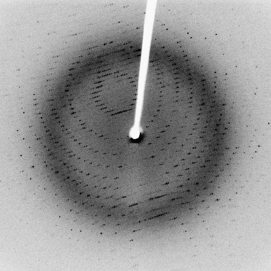
Reflections in Diffraction Patterns: Each dot, called a reflection, in this diffraction pattern forms from the constructive interference of scattered X-rays passing through a crystal. The data can be used to determine the crystalline structure.
Single Slit Diffraction
Single slit diffraction is the phenomenon that occurs when waves pass through a narrow gap and bend, forming an interference pattern.
learning objectives
- Formulate the Huygens’s Principle
Diffraction
As we explained in a previous atom, diffraction is defined as the bending of a wave around the edges of an opening or obstacle. Diffraction is a phenomenon all wave types can experience. It is explained by the Huygens-Fresnel Principle, and the principal of superposition of waves. The former states that every point on a wavefront is a source of wavelets. These wavelets spread out in the forward direction, at the same speed as the source wave. The new wavefront is a line tangent to all of the wavelets. The superposition principle states that at any point, the net result of multiple stimuli is the sum of all stimuli.
Single Slit Diffraction
In single slit diffraction, the diffraction pattern is determined by the wavelength and by the length of the slit. Figure 1 shows a visualization of this pattern. This is the most simplistic way of using the Huygens-Fresnel Principle, which was covered in a previous atom, and applying it to slit diffraction. But what happens when the slit is NOT the exact (or close to exact) length of a single wave?
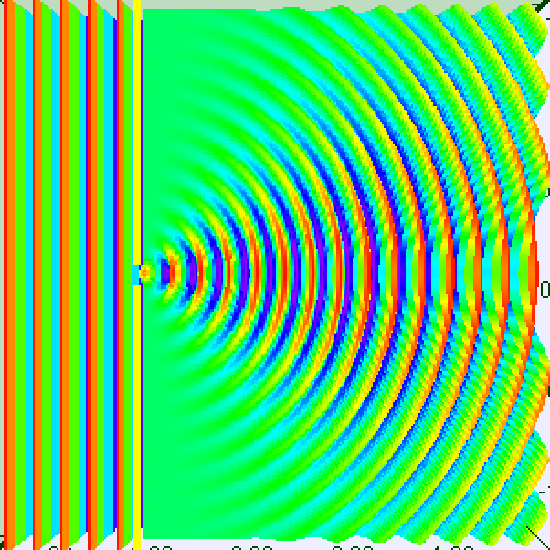
Single Slit Diffraction – One Wavelength: Visualization of single slit diffraction when the slit is equal to one wavelength.
A slit that is wider than a single wave will produce interference -like effects downstream from the slit. It is easier to understand by thinking of the slit not as a long slit, but as a number of point sources spaced evenly across the width of the slit. This can be seen in Figure 2.
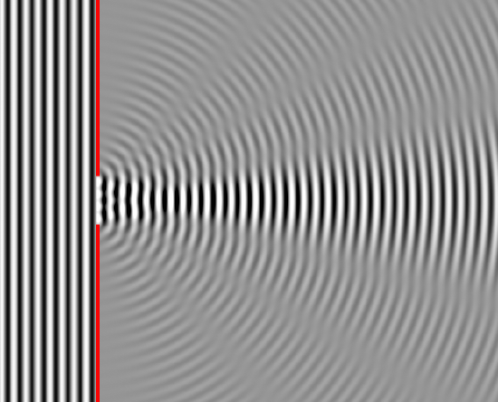
Single Slit Diffraction – Four Wavelengths: This figure shows single slit diffraction, but the slit is the length of 4 wavelengths.
To examine this effect better, lets consider a single monochromatic wavelength. This will produce a wavefront that is all in the same phase. Downstream from the slit, the light at any given point is made up of contributions from each of these point sources. The resulting phase differences are caused by the different in path lengths that the contributing portions of the rays traveled from the slit.
The variation in wave intensity can be mathematically modeled. From the center of the slit, the diffracting waves propagate radially. The angle of the minimum intensity (θmin) can be related to wavelength (λ) and the slit’s width (d) such that:
\[\mathrm { d } \sin \theta _ { \min } = \lambda\]
The intensity (I) of waves at any angle can also be calculated as a relation to slit width, wavelength and intensity of the original waves before passing through the slit:
\[\mathrm { I } ( \theta ) = \mathrm { I } _ { 0 } \left( \dfrac { \sin ( \pi \mathrm { x } ) } { \pi \mathrm { x } } \right) ^ { 2 }\]
where x is equal to:
\[\dfrac { \mathrm { d } } { \lambda } \sin \theta\]
The Rayleigh Criterion
The Rayleigh criterion determines the separation angle between two light sources which are distinguishable from each other. Consider to reflecting points from an object under a microscope
learning objectives
- Explain meaning of the Rayleigh criterion
Resolution Limits
Along with the diffraction effects that we have discussed in previous subsections this section, diffraction also limits the detail that we can obtain in images. shows three different circumstances of resolution limits due to diffraction:
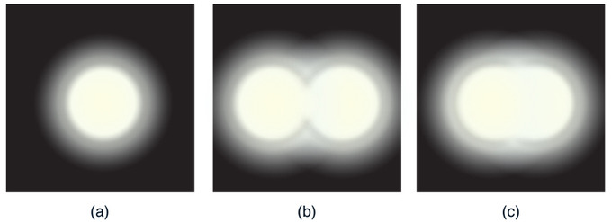
Resolution Limits: (a) Monochromatic light passed through a small circular aperture produces this diffraction pattern. (b) Two point light sources that are close to one another produce overlapping images because of diffraction. (c) If they are closer together, they cannot be resolved or distinguished.
- (a) shows a light passing through a small circular aperture. You do not see a sharp circular outline, but a spot with fuzzy edges. This is due to diffraction similar to that through a single slit.
- (b) shows two point sources close together, producing overlapping images. Due to the diffraction, you can just barely distinguish between the two point sources.
- (c) shows two point sources which are so close together that you can no longer distinguish between them.
This effect can be seen with light passing through small apertures or larger apertures. This same effect happens when light passes through our pupils, and this is why the human eye has limited acuity.
Rayleigh Criterion
In the 19th century, Lord Rayleigh invented a criteria for determining when two light sources were distinguishable from each other, or resolved. According to the criteria, two point sources are considered just resolved (just distinguishable enough from each other to recognize two sources) if the center of the diffraction pattern of one is directly overlapped by the first minimum of the diffraction pattern of the other. If the distance is greater between these points, the sources are well resolved (i.e., they are easy to distingush from each other). If the distance is smaller, they are not resolved (i.e., they cannot be distinguished from each other). The equation to determine this is:
\[\theta = 1.22 \dfrac { \lambda } { \mathrm { D } }\]
in this equation, θ is the angle the objects are separated by (in radians), λ is the wavelength of light, and D is the aperture diameter. Consequently, with optical microscopy the ability to resolve two closely spaced objects is limited by the wavelength of light.
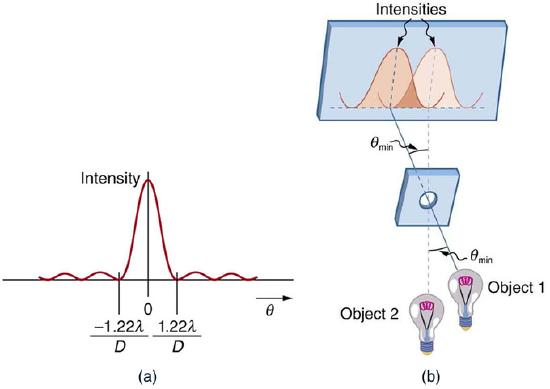
Rayleigh Criterion: (a) This is a graph of intensity of the diffraction pattern for a circular aperture. Note that, similar to a single slit, the central maximum is wider and brighter than those to the sides. (b) Two point objects produce overlapping diffraction patterns. Shown here is the Rayleigh criterion for being just resolvable. The central maximum of one pattern lies on the first minimum of the other.
Key Points
- Diffraction is the concept that is explained using Huygens’s Principle, and is defined as the bending of a wave around the edges of an opening or an obstacle.
- This principle can be used to define reflection, as shown in the figure. It can also be used to explain refraction and interference. Anything that experiences this phenomenon is a wave. By applying this theory to light passing through a slit, we can prove it is a wave.
- The principle can be shown with the equation below: s=vt s – distance v – propagation speed t – time Each point on the wavefront emits a wave at speed, v. The emitted waves are semicircular, and occur at t, time later. The new wavefront is tangent to the wavelets.
- The wave characteristics of light cause the light to pass through the slits and interfere with each other, producing the light and dark areas on the wall behind the slits. The light that appears on the wall behind the slits is partially absorbed by the wall, a characteristic of a particle.
- Constructive interference occurs when waves interfere with each other crest-to-crest and the waves are exactly in phase with each other. Destructive interference occurs when waves interfere with each other crest-to-trough (peak-to-valley) and are exactly out of phase with each other.
- Each point on the wall has a different distance to each slit; a different number of wavelengths fit in those two paths. If the two path lengths differ by a half a wavelength, the waves will interfere destructively. If the path length differs by a whole wavelength the waves interfere constructively.
- The directions of the diffracted beams depend on the spacing of the grating and the wavelength of the light so that the grating acts as the dispersive element.
- Gratings are commonly used in monochromators, spectrometers, wavelength division multiplexing devices, optical pulse compressing devices, and other optical instruments.
- Diffraction of X-ray is used in crystallography to produce the three-dimensional picture of the density of electrons within the crystal.
- The Huygens’s Principle states that every point on a wavefront is a source of wavelets. These wavelets spread out in the forward direction, at the same speed as the source wave. The new wavefront is a line tangent to all of the wavelets.
- If a slit is longer than a single wavelength, think of it instead as a number of point sources spaced evenly across the width of the slit.
- Downstream from a slit that is longer than a single wavelength, the light at any given point is made up of contributions from each of these point sources. The resulting phase differences are caused by the different in path lengths that the contributing portions of the rays traveled from the slit.
- Diffraction plays a large part in the resolution at which we are able to see things. There is a point where two light sources can be so close to each other that we cannot distinguish them apart.
- When two light sources are close to each other, they can be: unresolved (i.e., not able to distinguish one from the other), just resolved (i.e., only able to distinguish them apart from each other), and a little well resolved (i.e., easy to tell apart from one another).
- In order for two light sources to be just resolved, the center of one diffraction pattern must directly overlap with the first minimum of the other diffraction pattern.
Key Terms
- diffraction: The bending of a wave around the edges of an opening or an obstacle.
- constructive interference: Occurs when waves interfere with each other crest to crest and the waves are exactly in phase with each other.
- destructive interference: Occurs when waves interfere with each other crest to trough (peak to valley) and are exactly out of phase with each other.
- interference: An effect caused by the superposition of two systems of waves, such as a distortion on a broadcast signal due to atmospheric or other effects.
- iridescence: The condition or state of being iridescent; exhibition of colors like those of the rainbow; a prismatic play of color.
- diffraction: The bending of a wave around the edges of an opening or an obstacle.
- monochromatic: Describes a beam of light with a single wavelength (i.e., of one specific color or frequency).
- resolution: The degree of fineness with which an image can be recorded or produced, often expressed as the number of pixels per unit of length (typically an inch).
LICENSES AND ATTRIBUTIONS
CC LICENSED CONTENT, SHARED PREVIOUSLY
- Curation and Revision. Provided by: Boundless.com. License: CC BY-SA: Attribution-ShareAlike
CC LICENSED CONTENT, SPECIFIC ATTRIBUTION
- OpenStax College, Huygens's Principle: Diffraction. September 17, 2013. Provided by: OpenStax CNX. Located at: http://cnx.org/content/m42505/latest/. License: CC BY: Attribution
- Huygensu2013Fresnel principle. Provided by: Wikipedia. Located at: en.Wikipedia.org/wiki/Huygens%E2%80%93Fresnel_principle. License: CC BY-SA: Attribution-ShareAlike
- diffraction. Provided by: Wiktionary. Located at: en.wiktionary.org/wiki/diffraction. License: CC BY-SA: Attribution-ShareAlike
- OpenStax College, Huygens's Principle: Diffraction. January 11, 2013. Provided by: OpenStax CNX. Located at: http://cnx.org/content/m42505/latest/. License: CC BY: Attribution
- OpenStax College, Huygens's Principle: Diffraction. January 11, 2013. Provided by: OpenStax CNX. Located at: http://cnx.org/content/m42505/latest/. License: CC BY: Attribution
- OpenStax College, Huygens's Principle: Diffraction. January 11, 2013. Provided by: OpenStax CNX. Located at: http://cnx.org/content/m42505/latest/. License: CC BY: Attribution
- OpenStax College, Youngu2019s Double Slit Experiment. September 18, 2013. Provided by: OpenStax CNX. Located at: http://cnx.org/content/m42508/latest/. License: CC BY: Attribution
- Youngs double-slit experiment. Provided by: Wikipedia. Located at: en.Wikipedia.org/wiki/Youngs_double-slit_experiment. License: CC BY-SA: Attribution-ShareAlike
- Boundless. Provided by: Boundless Learning. Located at: www.boundless.com//physics/definition/destructive-interference. License: CC BY-SA: Attribution-ShareAlike
- Boundless. Provided by: Boundless Learning. Located at: www.boundless.com//physics/definition/constructive-interference. License: CC BY-SA: Attribution-ShareAlike
- OpenStax College, Huygens's Principle: Diffraction. January 11, 2013. Provided by: OpenStax CNX. Located at: http://cnx.org/content/m42505/latest/. License: CC BY: Attribution
- OpenStax College, Huygens's Principle: Diffraction. January 11, 2013. Provided by: OpenStax CNX. Located at: http://cnx.org/content/m42505/latest/. License: CC BY: Attribution
- OpenStax College, Huygens's Principle: Diffraction. January 11, 2013. Provided by: OpenStax CNX. Located at: http://cnx.org/content/m42505/latest/. License: CC BY: Attribution
- OpenStax College, Youngu2019s Double Slit Experiment. January 11, 2013. Provided by: OpenStax CNX. Located at: http://cnx.org/content/m42508/latest/. License: CC BY: Attribution
- OpenStax College, Youngu2019s Double Slit Experiment. January 11, 2013. Provided by: OpenStax CNX. Located at: http://cnx.org/content/m42508/latest/. License: CC BY: Attribution
- OpenStax College, Youngu2019s Double Slit Experiment. January 11, 2013. Provided by: OpenStax CNX. Located at: http://cnx.org/content/m42508/latest/. License: CC BY: Attribution
- Diffraction grating. Provided by: Wikipedia. Located at: en.Wikipedia.org/wiki/Diffraction_grating. License: CC BY-SA: Attribution-ShareAlike
- X-ray diffraction. Provided by: Wikipedia. Located at: en.Wikipedia.org/wiki/X-ray_diffraction. License: CC BY-SA: Attribution-ShareAlike
- X-rays. Provided by: Wikipedia. Located at: en.Wikipedia.org/wiki/X-rays. License: CC BY-SA: Attribution-ShareAlike
- Iridescent. Provided by: Wikipedia. Located at: en.Wikipedia.org/wiki/Iridescent. License: CC BY-SA: Attribution-ShareAlike
- Diffraction. Provided by: Wikipedia. Located at: en.Wikipedia.org/wiki/Diffraction%23Diffraction_grating. License: CC BY-SA: Attribution-ShareAlike
- Diffraction grating. Provided by: Wikipedia. Located at: en.Wikipedia.org/wiki/Diffraction_grating%23Natural_gratings. License: CC BY-SA: Attribution-ShareAlike
- X-ray crystallography. Provided by: Wikipedia. Located at: en.Wikipedia.org/wiki/X-ray_crystallography. License: CC BY-SA: Attribution-ShareAlike
- OpenStax College, Multiple Slit Diffraction. September 18, 2013. Provided by: OpenStax CNX. Located at: http://cnx.org/content/m42512/latest/. License: CC BY: Attribution
- diffraction. Provided by: Wiktionary. Located at: en.wiktionary.org/wiki/diffraction. License: CC BY-SA: Attribution-ShareAlike
- iridescence. Provided by: Wiktionary. Located at: en.wiktionary.org/wiki/iridescence. License: CC BY-SA: Attribution-ShareAlike
- interference. Provided by: Wiktionary. Located at: en.wiktionary.org/wiki/interference. License: CC BY-SA: Attribution-ShareAlike
- OpenStax College, Huygens's Principle: Diffraction. January 11, 2013. Provided by: OpenStax CNX. Located at: http://cnx.org/content/m42505/latest/. License: CC BY: Attribution
- OpenStax College, Huygens's Principle: Diffraction. January 11, 2013. Provided by: OpenStax CNX. Located at: http://cnx.org/content/m42505/latest/. License: CC BY: Attribution
- OpenStax College, Huygens's Principle: Diffraction. January 11, 2013. Provided by: OpenStax CNX. Located at: http://cnx.org/content/m42505/latest/. License: CC BY: Attribution
- OpenStax College, Youngu2019s Double Slit Experiment. January 11, 2013. Provided by: OpenStax CNX. Located at: http://cnx.org/content/m42508/latest/. License: CC BY: Attribution
- OpenStax College, Youngu2019s Double Slit Experiment. January 11, 2013. Provided by: OpenStax CNX. Located at: http://cnx.org/content/m42508/latest/. License: CC BY: Attribution
- OpenStax College, Youngu2019s Double Slit Experiment. January 11, 2013. Provided by: OpenStax CNX. Located at: http://cnx.org/content/m42508/latest/. License: CC BY: Attribution
- X-ray diffraction pattern 3clpro. Provided by: Wikipedia. Located at: en.Wikipedia.org/wiki/File:X-ray_diffraction_pattern_3clpro.jpg. License: CC BY-SA: Attribution-ShareAlike
- Provided by: Wikimedia. Located at: upload.wikimedia.org/Wikipedia/commons/thumb/d/d0/Compact_disc.svg/500px-Compact_disc.svg.png. License: CC BY-SA: Attribution-ShareAlike
- Paul Padley, Single Slit Diffraction. September 18, 2013. Provided by: OpenStax CNX. Located at: http://cnx.org/content/m12915/latest/. License: CC BY: Attribution
- Single slit diffraction. Provided by: Wikipedia. Located at: en.Wikipedia.org/wiki/Single_slit_diffraction%23Single-slit_diffraction. License: CC BY-SA: Attribution-ShareAlike
- Boundless. Provided by: Boundless Learning. Located at: www.boundless.com//physics/definition/monochromatic. License: CC BY-SA: Attribution-ShareAlike
- diffraction. Provided by: Wiktionary. Located at: en.wiktionary.org/wiki/diffraction. License: CC BY-SA: Attribution-ShareAlike
- OpenStax College, Huygens's Principle: Diffraction. January 11, 2013. Provided by: OpenStax CNX. Located at: http://cnx.org/content/m42505/latest/. License: CC BY: Attribution
- OpenStax College, Huygens's Principle: Diffraction. January 11, 2013. Provided by: OpenStax CNX. Located at: http://cnx.org/content/m42505/latest/. License: CC BY: Attribution
- OpenStax College, Huygens's Principle: Diffraction. January 11, 2013. Provided by: OpenStax CNX. Located at: http://cnx.org/content/m42505/latest/. License: CC BY: Attribution
- OpenStax College, Youngu2019s Double Slit Experiment. January 11, 2013. Provided by: OpenStax CNX. Located at: http://cnx.org/content/m42508/latest/. License: CC BY: Attribution
- OpenStax College, Youngu2019s Double Slit Experiment. January 11, 2013. Provided by: OpenStax CNX. Located at: http://cnx.org/content/m42508/latest/. License: CC BY: Attribution
- OpenStax College, Youngu2019s Double Slit Experiment. January 11, 2013. Provided by: OpenStax CNX. Located at: http://cnx.org/content/m42508/latest/. License: CC BY: Attribution
- X-ray diffraction pattern 3clpro. Provided by: Wikipedia. Located at: en.Wikipedia.org/wiki/File:X-ray_diffraction_pattern_3clpro.jpg. License: CC BY-SA: Attribution-ShareAlike
- Provided by: Wikimedia. Located at: upload.wikimedia.org/Wikipedia/commons/thumb/d/d0/Compact_disc.svg/500px-Compact_disc.svg.png. License: CC BY-SA: Attribution-ShareAlike
- Wavelength=slitwidthspectrum. Provided by: Wikipedia. Located at: en.Wikipedia.org/wiki/File:Wavelength=slitwidthspectrum.gif. License: CC BY-SA: Attribution-ShareAlike
- Wave Diffraction 4Lambda Slit. Provided by: Wikipedia. Located at: en.Wikipedia.org/wiki/File:Wave_Diffraction_4Lambda_Slit.png. License: Public Domain: No Known Copyright
- Rayleigh criterion. Provided by: Wikipedia. Located at: en.Wikipedia.org/wiki/Rayleigh_criterion%23Explanation. License: CC BY-SA: Attribution-ShareAlike
- OpenStax College, Limits of Resolution: The Rayleigh Criterion. September 17, 2013. Provided by: OpenStax CNX. Located at: http://cnx.org/content/m42517/latest/. License: CC BY: Attribution
- diffraction. Provided by: Wiktionary. Located at: en.wiktionary.org/wiki/diffraction. License: CC BY-SA: Attribution-ShareAlike
- resolution. Provided by: Wiktionary. Located at: en.wiktionary.org/wiki/resolution. License: CC BY-SA: Attribution-ShareAlike
- OpenStax College, Huygens's Principle: Diffraction. January 11, 2013. Provided by: OpenStax CNX. Located at: http://cnx.org/content/m42505/latest/. License: CC BY: Attribution
- OpenStax College, Huygens's Principle: Diffraction. January 11, 2013. Provided by: OpenStax CNX. Located at: http://cnx.org/content/m42505/latest/. License: CC BY: Attribution
- OpenStax College, Huygens's Principle: Diffraction. January 11, 2013. Provided by: OpenStax CNX. Located at: http://cnx.org/content/m42505/latest/. License: CC BY: Attribution
- OpenStax College, Youngu2019s Double Slit Experiment. January 11, 2013. Provided by: OpenStax CNX. Located at: http://cnx.org/content/m42508/latest/. License: CC BY: Attribution
- OpenStax College, Youngu2019s Double Slit Experiment. January 11, 2013. Provided by: OpenStax CNX. Located at: http://cnx.org/content/m42508/latest/. License: CC BY: Attribution
- OpenStax College, Youngu2019s Double Slit Experiment. January 11, 2013. Provided by: OpenStax CNX. Located at: http://cnx.org/content/m42508/latest/. License: CC BY: Attribution
- X-ray diffraction pattern 3clpro. Provided by: Wikipedia. Located at: en.Wikipedia.org/wiki/File:X-ray_diffraction_pattern_3clpro.jpg. License: CC BY-SA: Attribution-ShareAlike
- Provided by: Wikimedia. Located at: upload.wikimedia.org/Wikipedia/commons/thumb/d/d0/Compact_disc.svg/500px-Compact_disc.svg.png. License: CC BY-SA: Attribution-ShareAlike
- Wavelength=slitwidthspectrum. Provided by: Wikipedia. Located at: en.Wikipedia.org/wiki/File:Wavelength=slitwidthspectrum.gif. License: CC BY-SA: Attribution-ShareAlike
- Wave Diffraction 4Lambda Slit. Provided by: Wikipedia. Located at: en.Wikipedia.org/wiki/File:Wave_Diffraction_4Lambda_Slit.png. License: Public Domain: No Known Copyright
- OpenStax College, Limits of Resolution: The Rayleigh Criterion. January 12, 2013. Provided by: OpenStax CNX. Located at: http://cnx.org/content/m42517/latest/. License: CC BY: Attribution
- OpenStax College, Limits of Resolution: The Rayleigh Criterion. January 11, 2013. Provided by: OpenStax CNX. Located at: http://cnx.org/content/m42517/latest/. License: CC BY: Attribution

