Chemistry LibreTexts

19.4: Spectroscopic and Magnetic Properties of Coordination Compounds

  • Page ID
    452892
  • \( \newcommand{\vecs}[1]{\overset { \scriptstyle \rightharpoonup} {\mathbf{#1}} } \)

    \( \newcommand{\vecd}[1]{\overset{-\!-\!\rightharpoonup}{\vphantom{a}\smash {#1}}} \)

    \( \newcommand{\id}{\mathrm{id}}\) \( \newcommand{\Span}{\mathrm{span}}\)

    ( \newcommand{\kernel}{\mathrm{null}\,}\) \( \newcommand{\range}{\mathrm{range}\,}\)

    \( \newcommand{\RealPart}{\mathrm{Re}}\) \( \newcommand{\ImaginaryPart}{\mathrm{Im}}\)

    \( \newcommand{\Argument}{\mathrm{Arg}}\) \( \newcommand{\norm}[1]{\| #1 \|}\)

    \( \newcommand{\inner}[2]{\langle #1, #2 \rangle}\)

    \( \newcommand{\Span}{\mathrm{span}}\)

    \( \newcommand{\id}{\mathrm{id}}\)

    \( \newcommand{\Span}{\mathrm{span}}\)

    \( \newcommand{\kernel}{\mathrm{null}\,}\)

    \( \newcommand{\range}{\mathrm{range}\,}\)

    \( \newcommand{\RealPart}{\mathrm{Re}}\)

    \( \newcommand{\ImaginaryPart}{\mathrm{Im}}\)

    \( \newcommand{\Argument}{\mathrm{Arg}}\)

    \( \newcommand{\norm}[1]{\| #1 \|}\)

    \( \newcommand{\inner}[2]{\langle #1, #2 \rangle}\)

    \( \newcommand{\Span}{\mathrm{span}}\) \( \newcommand{\AA}{\unicode[.8,0]{x212B}}\)

    \( \newcommand{\vectorA}[1]{\vec{#1}}      % arrow\)

    \( \newcommand{\vectorAt}[1]{\vec{\text{#1}}}      % arrow\)

    \( \newcommand{\vectorB}[1]{\overset { \scriptstyle \rightharpoonup} {\mathbf{#1}} } \)

    \( \newcommand{\vectorC}[1]{\textbf{#1}} \)

    \( \newcommand{\vectorD}[1]{\overrightarrow{#1}} \)

    \( \newcommand{\vectorDt}[1]{\overrightarrow{\text{#1}}} \)

    \( \newcommand{\vectE}[1]{\overset{-\!-\!\rightharpoonup}{\vphantom{a}\smash{\mathbf {#1}}}} \)

    \( \newcommand{\vecs}[1]{\overset { \scriptstyle \rightharpoonup} {\mathbf{#1}} } \)

    \( \newcommand{\vecd}[1]{\overset{-\!-\!\rightharpoonup}{\vphantom{a}\smash {#1}}} \)

    \(\newcommand{\avec}{\mathbf a}\) \(\newcommand{\bvec}{\mathbf b}\) \(\newcommand{\cvec}{\mathbf c}\) \(\newcommand{\dvec}{\mathbf d}\) \(\newcommand{\dtil}{\widetilde{\mathbf d}}\) \(\newcommand{\evec}{\mathbf e}\) \(\newcommand{\fvec}{\mathbf f}\) \(\newcommand{\nvec}{\mathbf n}\) \(\newcommand{\pvec}{\mathbf p}\) \(\newcommand{\qvec}{\mathbf q}\) \(\newcommand{\svec}{\mathbf s}\) \(\newcommand{\tvec}{\mathbf t}\) \(\newcommand{\uvec}{\mathbf u}\) \(\newcommand{\vvec}{\mathbf v}\) \(\newcommand{\wvec}{\mathbf w}\) \(\newcommand{\xvec}{\mathbf x}\) \(\newcommand{\yvec}{\mathbf y}\) \(\newcommand{\zvec}{\mathbf z}\) \(\newcommand{\rvec}{\mathbf r}\) \(\newcommand{\mvec}{\mathbf m}\) \(\newcommand{\zerovec}{\mathbf 0}\) \(\newcommand{\onevec}{\mathbf 1}\) \(\newcommand{\real}{\mathbb R}\) \(\newcommand{\twovec}[2]{\left[\begin{array}{r}#1 \\ #2 \end{array}\right]}\) \(\newcommand{\ctwovec}[2]{\left[\begin{array}{c}#1 \\ #2 \end{array}\right]}\) \(\newcommand{\threevec}[3]{\left[\begin{array}{r}#1 \\ #2 \\ #3 \end{array}\right]}\) \(\newcommand{\cthreevec}[3]{\left[\begin{array}{c}#1 \\ #2 \\ #3 \end{array}\right]}\) \(\newcommand{\fourvec}[4]{\left[\begin{array}{r}#1 \\ #2 \\ #3 \\ #4 \end{array}\right]}\) \(\newcommand{\cfourvec}[4]{\left[\begin{array}{c}#1 \\ #2 \\ #3 \\ #4 \end{array}\right]}\) \(\newcommand{\fivevec}[5]{\left[\begin{array}{r}#1 \\ #2 \\ #3 \\ #4 \\ #5 \\ \end{array}\right]}\) \(\newcommand{\cfivevec}[5]{\left[\begin{array}{c}#1 \\ #2 \\ #3 \\ #4 \\ #5 \\ \end{array}\right]}\) \(\newcommand{\mattwo}[4]{\left[\begin{array}{rr}#1 \amp #2 \\ #3 \amp #4 \\ \end{array}\right]}\) \(\newcommand{\laspan}[1]{\text{Span}\{#1\}}\) \(\newcommand{\bcal}{\cal B}\) \(\newcommand{\ccal}{\cal C}\) \(\newcommand{\scal}{\cal S}\) \(\newcommand{\wcal}{\cal W}\) \(\newcommand{\ecal}{\cal E}\) \(\newcommand{\coords}[2]{\left\{#1\right\}_{#2}}\) \(\newcommand{\gray}[1]{\color{gray}{#1}}\) \(\newcommand{\lgray}[1]{\color{lightgray}{#1}}\) \(\newcommand{\rank}{\operatorname{rank}}\) \(\newcommand{\row}{\text{Row}}\) \(\newcommand{\col}{\text{Col}}\) \(\renewcommand{\row}{\text{Row}}\) \(\newcommand{\nul}{\text{Nul}}\) \(\newcommand{\var}{\text{Var}}\) \(\newcommand{\corr}{\text{corr}}\) \(\newcommand{\len}[1]{\left|#1\right|}\) \(\newcommand{\bbar}{\overline{\bvec}}\) \(\newcommand{\bhat}{\widehat{\bvec}}\) \(\newcommand{\bperp}{\bvec^\perp}\) \(\newcommand{\xhat}{\widehat{\xvec}}\) \(\newcommand{\vhat}{\widehat{\vvec}}\) \(\newcommand{\uhat}{\widehat{\uvec}}\) \(\newcommand{\what}{\widehat{\wvec}}\) \(\newcommand{\Sighat}{\widehat{\Sigma}}\) \(\newcommand{\lt}{<}\) \(\newcommand{\gt}{>}\) \(\newcommand{\amp}{&}\) \(\definecolor{fillinmathshade}{gray}{0.9}\)
    Learning Objectives

    By the end of this section, you will be able to:

    • Outline the basic premise of crystal field theory (CFT)
    • Identify molecular geometries associated with various d-orbital splitting patterns
    • Predict electron configurations of split d orbitals for selected transition metal atoms or ions
    • Explain spectral and magnetic properties in terms of CFT concepts

    The behavior of coordination compounds cannot be adequately explained by the same theories used for main group element chemistry. The observed geometries of coordination complexes are not consistent with hybridized orbitals on the central metal overlapping with ligand orbitals, as would be predicted by valence bond theory. The observed colors indicate that the d orbitals often occur at different energy levels rather than all being degenerate, that is, of equal energy, as are the three p orbitals. To explain the stabilities, structures, colors, and magnetic properties of transition metal complexes, a different bonding model has been developed. Just as valence bond theory explains many aspects of bonding in main group chemistry, crystal field theory is useful in understanding and predicting the behavior of transition metal complexes.

    Crystal Field Theory

    To explain the observed behavior of transition metal complexes (such as how colors arise), a model involving electrostatic interactions between the electrons from the ligands and the electrons in the unhybridized d orbitals of the central metal atom has been developed. This electrostatic model is crystal field theory (CFT). It allows us to understand, interpret, and predict the colors, magnetic behavior, and some structures of coordination compounds of transition metals.

    CFT focuses on the nonbonding electrons on the central metal ion in coordination complexes not on the metal-ligand bonds. Like valence bond theory, CFT tells only part of the story of the behavior of complexes. However, it tells the part that valence bond theory does not. In its pure form, CFT ignores any covalent bonding between ligands and metal ions. Both the ligand and the metal are treated as infinitesimally small point charges.

    All electrons are negative, so the electrons donated from the ligands will repel the electrons of the central metal. Let us consider the behavior of the electrons in the unhybridized d orbitals in an octahedral complex. The five d orbitals consist of lobe-shaped regions and are arranged in space, as shown in Figure \(\PageIndex{1}\). In an octahedral complex, the six ligands coordinate along the axes.

    This figure includes diagrams of five d orbitals. Each diagram includes three axes. The z-axis is vertical and is denoted with an upward pointing arrow. It is labeled “z” in the first diagram. Arrows similarly identify the x-axis with an arrow pointing from the rear left to the right front, diagonally across the figure and the y-axis with an arrow pointing from the left front diagonally across the figure to the right rear of the diagram. These axes are similarly labeled as “x” and “y.” In this first diagram, four orange balloon-like shapes extend from a point at the origin out along the x- and y- axes in positive and negative directions covering just over half the length of the positive and negative x- and y- axes. Beneath the diagram is the label, “d subscript ( x superscript 2 minus y superscript 2 ).” The second diagram just right of the first is similar except the x, y, and z labels have been replaced in each instance with the letter L. Only a pair of the orange balloon-like shapes are present and extend from the origin above and below along the vertical axis. An orange toroidal or donut shape is positioned around the origin, oriented through the x- and y- axes. This shape extends out to about a third of the length of the positive and negative regions of the x- and y- axes. This diagram is labeled, “d subscript ( z superscript 2 ).” The third through fifth diagrams, similar to the first, show four orange balloon-like shapes. These diagrams differ however in the orientation of the shapes along the axes and the x-, y-, and z-axis labels have each been replaced with the letter L. Planes are added to the figures to help show the orientation differences with these diagrams. In the third diagram, a green plane is oriented vertically through the length of the x-axis and a blue plane is oriented horizontally through the length of the y-axis. The balloon shapes extend from the origin to the spaces between the positive z- and negative y- axes, positive z- and positive y- axes, negative z- and negative y- axes, and negative z- and positive y- axes. This diagram is labeled, “d subscript ( y z ).” In the fourth diagram, a green plane is oriented vertically through the x- and y- axes and a blue plane is oriented horizontally through the length of the x-axis. The balloon shapes extend from the origin to the spaces between the positive z- and negative x- axes, positive z- and positive x- axes, negative z- and negative x- axes, and negative z- and positive x- axes. This diagram is labeled “d subscript ( x z ).” In the fifth diagram, a pink plane is oriented vertically through the length of the y-axis and a green plane is oriented vertically through the length of the x-axis. The balloon shapes extend from the origin to the spaces between the positive x- and negative y- axes, positive x- and positive y- axes, negative x- and negative y- axes, and negative x- and positive y- axes. This diagram is labeled, “d subscript ( x y ).”
    Figure \(\PageIndex{1}\): The directional characteristics of the five d orbitals are shown here. The shaded portions indicate the phase of the orbitals. The ligands (L) coordinate along the axes. For clarity, the ligands have been omitted from the orbital so that the axis labels could be shown.

    In an uncomplexed metal ion in the gas phase, the electrons are distributed among the five d orbitals in accord with Hund's rule because the orbitals all have the same energy. However, when ligands coordinate to a metal ion, the energies of the d orbitals are no longer the same.

    In octahedral complexes, the lobes in two of the five d orbitals, the \(d_{z^2}\) and \(d_{x^2−y^2}\) orbitals, point toward the ligands (Figure \(\PageIndex{1}\)). These two orbitals are called the \(e_g\) orbitals (the symbol actually refers to the symmetry of the orbitals, but we will use it as a convenient name for these two orbitals in an octahedral complex). The other three orbitals, the \(d_{xy}\), \(d_{xz}\), and \(d_{yz}\) orbitals, have lobes that point between the ligands and are called the \(t_{2g}\) orbitals (again, the symbol really refers to the symmetry of the orbitals). As six ligands approach the metal ion along the axes of the octahedron, their point charges repel the electrons in the d orbitals of the metal ion. However, the repulsions between the electrons in the eg orbitals (the \(d_{z^2}\) and \(d_{x^2−y^2}\) orbitals) and the ligands are greater than the repulsions between the electrons in the \(t_{2g}\) orbitals (the \(d_{zy}\), \(d_{xz}\), and \(d_{yz}\) orbitals) and the ligands. This is because the lobes of the eg orbitals point directly at the ligands, whereas the lobes of the \(t_{2g}\) orbitals point between them. Thus, electrons in the eg orbitals of the metal ion in an octahedral complex have higher potential energies than those of electrons in the \(t_{2g}\) orbitals. The difference in energy may be represented as shown in Figure \(\PageIndex{2}\).

    A diagram is shown with a vertical arrow pointing upward along the height of the diagram at its left side. This arrow is labeled, “E.” to the right of this arrow are two rows of squares outlined in yellow. The first row has three evenly spaced squares labeled left to right, “d subscript ( x y ),” “d subscript ( x z ),” and, “d subscript ( y z ).” The second row is positioned just above the first and includes two evenly spaced squares labeled, “d subscript ( z superscript 2 ),” and, “d subscript ( x superscript 2 minus y superscript 2 ).” At the right end of the diagram, a short horizontal line segment is drawn just right of the lower side of the rightmost square. A double sided arrow extends from this line segment to a second horizontal line segment directly above the first and right of the lower side of the squares in the second row. The arrow is labeled “ capital delta subscript oct.”. The lower horizontal line segment is similarly labeled “t subscript 2 g orbitals” and the upper line segment is labeled “e subscript g orbitals.”
    Figure \(\PageIndex{2}\): In octahedral complexes, the eg orbitals are destabilized (higher in energy) compared to the t2g orbitals because the ligands interact more strongly with the d orbitals at which they are pointed directly.

    The difference in energy between the eg and the t2g orbitals is called the crystal field splitting and is symbolized by \(Δ_{oct}\), where oct stands for octahedral.

    The magnitude of Δoct depends on many factors, including the nature of the six ligands located around the central metal ion, the charge on the metal, and whether the metal is using 3d, 4d, or 5d orbitals. Different ligands produce different crystal field splittings. The increasing crystal field splitting produced by ligands is expressed in the spectrochemical series, a short version of which is given here:

    \[\Large \xrightarrow[\text{a few ligands of the spectrochemical series, in order of increasing field strength of the ligand}]{\ce{I^{-}< Br^{-}< Cl^{-}< F^{-} < H_2O < NH_3 < en < NO_2^{-} < CN^{-}}} \nonumber \]

    In this series, ligands on the left cause small crystal field splittings and are weak-field ligands, whereas those on the right cause larger splittings and are strong-field ligands. Thus, the Δoct value for an octahedral complex with iodide ligands (I) is much smaller than the Δoct value for the same metal with cyanide ligands (CN).

    Electrons in the d orbitals follow the aufbau (“filling up”) principle, which says that the orbitals will be filled to give the lowest total energy, just as in main group chemistry. When two electrons occupy the same orbital, the like charges repel each other. The energy needed to pair up two electrons in a single orbital is called the pairing energy (P). Electrons will always singly occupy each orbital in a degenerate set before pairing. P is similar in magnitude to Δoct. When electrons fill the d orbitals, the relative magnitudes of Δoct and P determine which orbitals will be occupied.

    In [Fe(CN)6]4−, the strong field of six cyanide ligands produces a large Δoct. Under these conditions, the electrons require less energy to pair than they require to be excited to the eg orbitals (Δoct > P). The six 3d electrons of the Fe2+ ion pair in the three t2g orbitals (Figure \(\PageIndex{3}\)). Complexes in which the electrons are paired because of the large crystal field splitting are called low-spin complexes because the number of unpaired electrons (spins) is minimized.

    A diagram is shown with a vertical arrow pointing upward along the height of the diagram at its left side. This arrow is labeled, “E.” to the right of this arrow are several rows of squares outlined in yellow. The first row has three linked squares at the lower right side of the diagram labeled, “[ F e ( C N ) subscript 6 ] superscript 4 negative sign.” Each square contains two half arrows, with the left half arrow pointing up and the right half arrow pointing down. A second row is positioned just above and to the left of the first, with the bottom of the squares at a height equal with the top of the squares in the first row. This group is also composed of 3 linked squares. The square to the left contains two half arrows, with the left half arrow pointing up and the right half arrow pointing down. The remaining two squares in this row only have upward pointing half arrows. At the bottom of the figure, just below this group is the label “[ F e ( H subscript 2 O ) subscript 6] superscript 2 plus sign.” To the left of this row, a third row that includes 5 linked squares is positioned with the lower edge of the squares at a height equal to the tops of the squares in row two. The square to the left contains two half arrows, one up and one down. All other squares in this group contain single upward pointing arrows. At the bottom of the figure beneath this row appears the label, “F e superscript 2 plus sign no ligands.” A fourth row composed of 2 linked squares appears to the right and above the second row. The lower edge of the squares is at a height level with the top of the squares of the third row. Each of these squares contains a single upward pointing half arrow. A fifth row of 2 squares is positioned above and to the right directly above the first row with the base of the squares positioned at a level equal to the top of the previous row of squares. These squares are empty. At the right of the diagram, a short horizontal line segment is drawn just right of the lower side of the rightmost square of the first row. A double-headed arrow extends from this line segment to a second horizontal line segment directly above the first and right of the lower side of the fifth row of squares. The arrow is labeled, “Low spin, large delta subscript oct,” to the right. The lower horizontal line segment is similarly labeled, “t subscript 2 g,” and the upper line segment is labeled, “e subscript g.” To the right of the second and fourth rows, a short horizontal line segment is drawn just right of the lower side of the rightmost square of the second row. A double-headed arrow extends from this line segment to a second horizontal line segment directly above the first and right of the lower side of the fourth row of squares. The arrow is labeled, “High spin, small capital delta subscript oct,” to the right. The lower horizontal line segment is similarly labeled, “t subscript 2 g,” and the upper line segment is labeled, “e subscript g.”
    Figure \(\PageIndex{3}\): Iron(II) complexes have six electrons in the 5d orbitals. In the absence of a crystal field, the orbitals are degenerate. For coordination complexes with strong-field ligands such as [Fe(CN)6]4−, Δoct is greater than P, and the electrons pair in the lower energy t2g orbitals before occupying the eg orbitals. With weak-field ligands such as H2O, the ligand field splitting is less than the pairing energy, Δoct less than P, so the electrons occupy all d orbitals singly before any pairing occurs.

    In [Fe(H2O)6]2+, on the other hand, the weak field of the water molecules produces only a small crystal field splitting (Δoct < P). Because it requires less energy for the electrons to occupy the eg orbitals than to pair together, there will be an electron in each of the five 3d orbitals before pairing occurs. For the six d electrons on the iron(II) center in [Fe(H2O)6]2+, there will be one pair of electrons and four unpaired electrons (Figure \(\PageIndex{3}\)). Complexes such as the [Fe(H2O)6]2+ ion, in which the electrons are unpaired because the crystal field splitting is not large enough to cause them to pair, are called high-spin complexes because the number of unpaired electrons (spins) is maximized.

    A similar line of reasoning shows why the [Fe(CN)6]3− ion is a low-spin complex with only one unpaired electron, whereas both the [Fe(H2O)6]3+ and [FeF6]3− ions are high-spin complexes with five unpaired electrons.

    Example \(\PageIndex{1}\): High- and Low-Spin Complexes

    Predict the number of unpaired electrons.

    1. \(\ce{K3[CrI6]}\)
    2. \(\ce{[Cu(en)2(H2O)2]Cl2}\)
    3. \(\ce{Na3[Co(NO2)6]}\)
    Solution

    The complexes are octahedral.

    1. Cr3+ has a d3 configuration. These electrons will all be unpaired.
    2. Cu2+ is d9, so there will be one unpaired electron.
    3. Co3+ has d6 valence electrons, so the crystal field splitting will determine how many are paired. Nitrite is a strong-field ligand, so the complex will be low spin. Six electrons will go in the t2g orbitals, leaving 0 unpaired.
    Exercise \(\PageIndex{1}\)

    The size of the crystal field splitting only influences the arrangement of electrons when there is a choice between pairing electrons and filling the higher-energy orbitals. For which d-electron configurations will there be a difference between high- and low-spin configurations in octahedral complexes?

    Answer

    d4, d5, d6, and d7

    Example \(\PageIndex{2}\): CFT for Other Geometries

    CFT is applicable to molecules in geometries other than octahedral. In octahedral complexes, remember that the lobes of the eg set point directly at the ligands. For tetrahedral complexes, the d orbitals remain in place, but now we have only four ligands located between the axes (Figure \(\PageIndex{4}\)). None of the orbitals points directly at the tetrahedral ligands. However, the eg set (along the Cartesian axes) overlaps with the ligands less than does the t2g set. By analogy with the octahedral case, predict the energy diagram for the d orbitals in a tetrahedral crystal field. To avoid confusion, the octahedral eg set becomes a tetrahedral e set, and the octahedral t2g set becomes a t2 set.
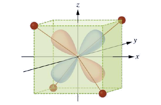
    This figure includes a three dimensional diagram. At the origin appears the letter M. An arrow, labeled, “z,” at its tip, points upward through the center. An arrow, labeled, “x,” at its tip, points right through the center. A third arrow, labeled, “y,” at its tip, points through the center from the left front to the right back portion of the diagram. A rectangular prism is drawn in green, extending out approximately three-quarters of the lengths from the origin along the positive and negative x-, y-, and z- axes. Small red spheres are positioned at the left upper front, right upper back, right lower front, and left lower back vertices of the prism. Red lines extend from the central M through the prism to these four small red spheres.
    Figure \(\PageIndex{4}\): This diagram shows the orientation of the tetrahedral ligands with respect to the axis system for the orbitals.
    Solution

    Since CFT is based on electrostatic repulsion, the orbitals closer to the ligands will be destabilized and raised in energy relative to the other set of orbitals. The splitting is less than for octahedral complexes because the overlap is less, so \(Δ_{tet}\) is usually small \(\left(\Delta_{\text {tet}}=\frac{4}{9} \Delta_{oct}\right)\)
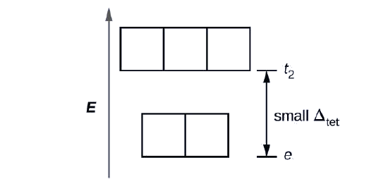
    A diagram is shown with a vertical arrow pointing upward along the height of the diagram at its left side. This arrow is labeled, “E.” to the right of this arrow are two rows of squares outlined in yellow. The first row has two adjacent squares. The second row is positioned just above the first and includes three adjacent squares. At the right side of the diagram, a short horizontal line segment is drawn just right of the lower side of the rightmost square in the first row. A double-headed arrow extends from this line segment to a second horizontal line segment directly above the first and right of the lower side of the squares in the second row. The arrow is labeled, “small capital delta subscript tet,” to the right. The lower horizontal line segment is similarly labeled, “e subscript,” and the upper line segment is labeled, “t subscript 2.”

    Exercise \(\PageIndex{2}\)

    Explain how many unpaired electrons a tetrahedral d4 ion will have.

    Answer

    4; because \(Δ_{tet}\) is small, all tetrahedral complexes are high spin and the electrons go into the t2 orbitals before pairing

    The other common geometry is square planar. It is possible to consider a square planar geometry as an octahedral structure with a pair of trans ligands removed. The removed ligands are assumed to be on the z-axis. This changes the distribution of the d orbitals, as orbitals on or near the z-axis become more stable, and those on or near the x- or y-axes become less stable. This results in the octahedral t2g and the eg sets splitting and gives a more complicated pattern, as depicted below:

    A diagram is shown with four rows of vertically oriented rectangles. The lower level has two rectangles with a space between them. The rectangle on the left is labeled, “d subscript x z,” below. The rectangle to its right is similarly labeled, “d subscript y z.” Just above, the second row contains only 1 rectangle above and between the lower two. This rectangle is labeled, “d subscript z squared.” Just above, the third row contains only 1 rectangle directly above. This rectangle is labeled, “d subscript x z.” Just above, the fourth row contains only 1 rectangle directly above. This rectangle is labeled, “d subscript x squared minus y squared.”

    Magnetic Moments of Molecules and Ions

    Experimental evidence of magnetic measurements supports the theory of high- and low-spin complexes. Remember that molecules such as O2 that contain unpaired electrons are paramagnetic. Paramagnetic substances are attracted to magnetic fields. Many transition metal complexes have unpaired electrons and hence are paramagnetic. Molecules such as N2 and ions such as Na+ and [Fe(CN)6]4− that contain no unpaired electrons are diamagnetic. Diamagnetic substances have a slight tendency to be repelled by magnetic fields.

    When an electron in an atom or ion is unpaired, the magnetic moment due to its spin makes the entire atom or ion paramagnetic. The size of the magnetic moment of a system containing unpaired electrons is related directly to the number of such electrons: the greater the number of unpaired electrons, the larger the magnetic moment. Therefore, the observed magnetic moment is used to determine the number of unpaired electrons present. The measured magnetic moment of low-spin d6 [Fe(CN)6]4− confirms that iron is diamagnetic, whereas high-spin d6 [Fe(H2O)6]2+ has four unpaired electrons with a magnetic moment that confirms this arrangement.

    Colors of Transition Metal Complexes

    When atoms or molecules absorb light at the proper frequency, their electrons are excited to higher-energy orbitals. For many main group atoms and molecules, the absorbed photons are in the ultraviolet range of the electromagnetic spectrum, which cannot be detected by the human eye. For coordination compounds, the energy difference between the d orbitals often allows photons in the visible range to be absorbed.

    The human eye perceives a mixture of all the colors, in the proportions present in sunlight, as white light. Complementary colors, those located across from each other on a color wheel, are also used in color vision. The eye perceives a mixture of two complementary colors, in the proper proportions, as white light. Likewise, when a color is missing from white light, the eye sees its complement. For example, when red photons are absorbed from white light, the eyes see the color green. When violet photons are removed from white light, the eyes see lemon yellow. The blue color of the [Cu(NH3)4]2+ ion results because this ion absorbs orange and red light, leaving the complementary colors of blue and green (Figure \(\PageIndex{5}\)).

    This figure includes three diagrams. In a, red, orange, yellow, green, blue, indigo, and violet incident arrows point from the upper left to the lower right toward one black, one white, and two yellow rectangular surfaces. No arrows are indicated leaving the black surface. On the white surface, arrows of all included colors extend from the surface of the rectangle extending from just right of the tips of the incident arrows that approach the rectangle to the upper right. For the first yellow surface, only a yellow arrow extends from a point just past the tip of the yellow incident arrow to the upper right. For the second yellow surface, all colors of arrows except indigo extend from points just past the tips of the incident arrows to the upper right. In b, a circle shaded in red at the upper left blends to orange, yellow, green, blue, indigo, and violet moving clockwise about the circle. The leftmost side of the red region has a radius that is labeled, “800 n m,” at the edge of the circle. A radius drawn to the top of the circle in the red-orange region is labeled, “620 n m.” A radius drawn to a point near the center of the first quadrant of the circle in the orange-yellow region is labeled, “580 n m.” A radius drawn to a point near the center of the second quadrant of the circle in the yellow-green region is labeled, “560 n m.” A radius drawn to the bottom of the circle in the blue region is labeled, “490 n m.” A radius drawn to a point near the center of the third quadrant of the circle in the indigo region is labeled, “430 n m.” An unlabeled radius is drawn to the leftmost point on the circle in the violet region. The violet region ends where the red region began on the circle. This radius is labeled, “400 n m,” just to the left and below the, “800 n m,” label associated with the red region. In c, a test tube containing a blue substance is shown. To the left of the test tube, incident colored arrows are shown pointing to the test tube. The colors of the arrows in order from bottom to top are red, orange, yellow, green, blue, indigo, and violet. Above these arrows is the label, “White light.” To the right of the test tube, yellow, green, blue, indigo, and violet arrows point right. These arrows are positioned at the same level on the test tube as their matching incident arrows on the left of the test tube. Above these arrows is the label, “Blue-appearing light.”
    Figure \(\PageIndex{5}\): (a) An object is black if it absorbs all colors of light. If it reflects all colors of light, it is white. An object has a color if it absorbs all colors except one, such as this yellow strip. The strip also appears yellow if it absorbs the complementary color from white light (in this case, indigo). (b) Complementary colors are located directly across from one another on the color wheel. (c) A solution of [Cu(NH3)4]2+ ions absorbs red and orange light, so the transmitted light appears as the complementary color, blue.
    Example \(\PageIndex{3}\): Colors of Complexes

    The octahedral complex [Ti(H2O)6]3+ has a single d electron. To excite this electron from the ground state t2g orbital to the eg orbital, this complex absorbs light from 450 to 600 nm. The maximum absorbance corresponds to Δoct and occurs at 499 nm. Calculate the value of Δoct in Joules and predict what color the solution will appear.

    Solution

    Using Planck's equation (refer to the section on electromagnetic energy), we calculate:

    \[\nu =\frac{c}{\lambda} \text { so } \frac{3.00 \times 10^8 m / s }{\frac{499 nm \times 1 m }{10^9 nm }}=6.01 \times 10^{14} Hz \nonumber \]

    \[E=h \nu \text { so } 6.63 \times 10^{-34} J \cdot s \times 6.01 \times 10^{14} Hz =3.99 \times 10^{-19} \text { Joules/ion } \nonumber \]

    Because the complex absorbs 600 nm (orange) through 450 (blue), the indigo, violet, and red wavelengths will be transmitted, and the complex will appear purple.

    Exercise \(\PageIndex{3}\)

    A complex that appears green, absorbs photons of what wavelengths?

    Answer

    red, 620–800 nm

    Small changes in the relative energies of the orbitals that electrons are transitioning between can lead to drastic shifts in the color of light absorbed. Therefore, the colors of coordination compounds depend on many factors. As shown in Figure \(\PageIndex{6}\), different aqueous metal ions can have different colors. In addition, different oxidation states of one metal can produce different colors, as shown for the vanadium complexes in the link below.
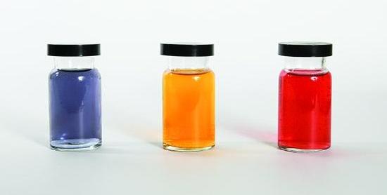
    This figure shows three containers filled with liquids of different colors. The first appears to be purple, the second, orange, and the third red.
    Figure \(\PageIndex{6}\): The partially filled d orbitals of the stable ions Cr3+(aq), Fe3+(aq), and Co2+(aq) (left, center and right, respectively) give rise to various colors. (credit: Sahar Atwa)

    The specific ligands coordinated to the metal center also influence the color of coordination complexes. For example, the iron(II) complex [Fe(H2O)6]SO4 appears blue-green because the high-spin complex absorbs photons in the red wavelengths (Figure \(\PageIndex{7}\)). In contrast, the low-spin iron(II) complex K4[Fe(CN)6] appears pale yellow because it absorbs higher-energy violet photons.

    Two photos are shown. Photo a on the left shows a small mound of a white crystalline powder with a very faint yellow tint on a watch glass. Photo b shows a small mound of a yellow-tan crystalline powder.
    Figure \(\PageIndex{7}\): Both (a) hexaaquairon(II) sulfate and (b) potassium hexacyanoferrate(II) contain d6 iron(II) octahedral metal centers, but they absorb photons in different ranges of the visible spectrum.

    Watch this video of the reduction of vanadium complexes to observe the colorful effect of changing oxidation states.

    In general, strong-field ligands cause a large split in the energies of d orbitals of the central metal atom (large Δoct). Transition metal coordination compounds with these ligands are yellow, orange, or red because they absorb higher-energy violet or blue light. On the other hand, coordination compounds of transition metals with weak-field ligands are often blue-green, blue, or indigo because they absorb lower-energy yellow, orange, or red light.

    A coordination compound of the Cu+ ion has a d10 configuration, and all the eg orbitals are filled. To excite an electron to a higher level, such as the 4p orbital, photons of very high energy are necessary. This energy corresponds to very short wavelengths in the ultraviolet region of the spectrum. No visible light is absorbed, so the eye sees no change, and the compound appears white or colorless. A solution containing [Cu(CN)2], for example, is colorless. On the other hand, octahedral Cu2+ complexes have a vacancy in the eg orbitals, and electrons can be excited to this level. The wavelength (energy) of the light absorbed corresponds to the visible part of the spectrum, and Cu2+ complexes are almost always colored—blue, blue-green violet, or yellow (Figure \(\PageIndex{8}\)). Although CFT successfully describes many properties of coordination complexes, molecular orbital explanations (beyond the introductory scope provided here) are required to understand fully the behavior of coordination complexes.

    Two photos are shown. Photo a on the left shows a small mound of a white crystalline powder on a watch glass. Photo b shows a small mound of a bright blue crystalline powder.
    Figure \(\PageIndex{8}\): (a) Copper(I) complexes with d10 configurations such as CuI tend to be colorless, whereas (b) d9 copper(II) complexes such as Cu(NO3)2·5H2O are brightly colored.

    This page titled 19.4: Spectroscopic and Magnetic Properties of Coordination Compounds is shared under a CC BY 4.0 license and was authored, remixed, and/or curated by OpenStax via source content that was edited to the style and standards of the LibreTexts platform.