Resonant vs. Nonresonant Raman Spectroscopy
- Page ID
- 1851
\( \newcommand{\vecs}[1]{\overset { \scriptstyle \rightharpoonup} {\mathbf{#1}} } \)
\( \newcommand{\vecd}[1]{\overset{-\!-\!\rightharpoonup}{\vphantom{a}\smash {#1}}} \)
\( \newcommand{\id}{\mathrm{id}}\) \( \newcommand{\Span}{\mathrm{span}}\)
( \newcommand{\kernel}{\mathrm{null}\,}\) \( \newcommand{\range}{\mathrm{range}\,}\)
\( \newcommand{\RealPart}{\mathrm{Re}}\) \( \newcommand{\ImaginaryPart}{\mathrm{Im}}\)
\( \newcommand{\Argument}{\mathrm{Arg}}\) \( \newcommand{\norm}[1]{\| #1 \|}\)
\( \newcommand{\inner}[2]{\langle #1, #2 \rangle}\)
\( \newcommand{\Span}{\mathrm{span}}\)
\( \newcommand{\id}{\mathrm{id}}\)
\( \newcommand{\Span}{\mathrm{span}}\)
\( \newcommand{\kernel}{\mathrm{null}\,}\)
\( \newcommand{\range}{\mathrm{range}\,}\)
\( \newcommand{\RealPart}{\mathrm{Re}}\)
\( \newcommand{\ImaginaryPart}{\mathrm{Im}}\)
\( \newcommand{\Argument}{\mathrm{Arg}}\)
\( \newcommand{\norm}[1]{\| #1 \|}\)
\( \newcommand{\inner}[2]{\langle #1, #2 \rangle}\)
\( \newcommand{\Span}{\mathrm{span}}\) \( \newcommand{\AA}{\unicode[.8,0]{x212B}}\)
\( \newcommand{\vectorA}[1]{\vec{#1}} % arrow\)
\( \newcommand{\vectorAt}[1]{\vec{\text{#1}}} % arrow\)
\( \newcommand{\vectorB}[1]{\overset { \scriptstyle \rightharpoonup} {\mathbf{#1}} } \)
\( \newcommand{\vectorC}[1]{\textbf{#1}} \)
\( \newcommand{\vectorD}[1]{\overrightarrow{#1}} \)
\( \newcommand{\vectorDt}[1]{\overrightarrow{\text{#1}}} \)
\( \newcommand{\vectE}[1]{\overset{-\!-\!\rightharpoonup}{\vphantom{a}\smash{\mathbf {#1}}}} \)
\( \newcommand{\vecs}[1]{\overset { \scriptstyle \rightharpoonup} {\mathbf{#1}} } \)
\( \newcommand{\vecd}[1]{\overset{-\!-\!\rightharpoonup}{\vphantom{a}\smash {#1}}} \)
\(\newcommand{\avec}{\mathbf a}\) \(\newcommand{\bvec}{\mathbf b}\) \(\newcommand{\cvec}{\mathbf c}\) \(\newcommand{\dvec}{\mathbf d}\) \(\newcommand{\dtil}{\widetilde{\mathbf d}}\) \(\newcommand{\evec}{\mathbf e}\) \(\newcommand{\fvec}{\mathbf f}\) \(\newcommand{\nvec}{\mathbf n}\) \(\newcommand{\pvec}{\mathbf p}\) \(\newcommand{\qvec}{\mathbf q}\) \(\newcommand{\svec}{\mathbf s}\) \(\newcommand{\tvec}{\mathbf t}\) \(\newcommand{\uvec}{\mathbf u}\) \(\newcommand{\vvec}{\mathbf v}\) \(\newcommand{\wvec}{\mathbf w}\) \(\newcommand{\xvec}{\mathbf x}\) \(\newcommand{\yvec}{\mathbf y}\) \(\newcommand{\zvec}{\mathbf z}\) \(\newcommand{\rvec}{\mathbf r}\) \(\newcommand{\mvec}{\mathbf m}\) \(\newcommand{\zerovec}{\mathbf 0}\) \(\newcommand{\onevec}{\mathbf 1}\) \(\newcommand{\real}{\mathbb R}\) \(\newcommand{\twovec}[2]{\left[\begin{array}{r}#1 \\ #2 \end{array}\right]}\) \(\newcommand{\ctwovec}[2]{\left[\begin{array}{c}#1 \\ #2 \end{array}\right]}\) \(\newcommand{\threevec}[3]{\left[\begin{array}{r}#1 \\ #2 \\ #3 \end{array}\right]}\) \(\newcommand{\cthreevec}[3]{\left[\begin{array}{c}#1 \\ #2 \\ #3 \end{array}\right]}\) \(\newcommand{\fourvec}[4]{\left[\begin{array}{r}#1 \\ #2 \\ #3 \\ #4 \end{array}\right]}\) \(\newcommand{\cfourvec}[4]{\left[\begin{array}{c}#1 \\ #2 \\ #3 \\ #4 \end{array}\right]}\) \(\newcommand{\fivevec}[5]{\left[\begin{array}{r}#1 \\ #2 \\ #3 \\ #4 \\ #5 \\ \end{array}\right]}\) \(\newcommand{\cfivevec}[5]{\left[\begin{array}{c}#1 \\ #2 \\ #3 \\ #4 \\ #5 \\ \end{array}\right]}\) \(\newcommand{\mattwo}[4]{\left[\begin{array}{rr}#1 \amp #2 \\ #3 \amp #4 \\ \end{array}\right]}\) \(\newcommand{\laspan}[1]{\text{Span}\{#1\}}\) \(\newcommand{\bcal}{\cal B}\) \(\newcommand{\ccal}{\cal C}\) \(\newcommand{\scal}{\cal S}\) \(\newcommand{\wcal}{\cal W}\) \(\newcommand{\ecal}{\cal E}\) \(\newcommand{\coords}[2]{\left\{#1\right\}_{#2}}\) \(\newcommand{\gray}[1]{\color{gray}{#1}}\) \(\newcommand{\lgray}[1]{\color{lightgray}{#1}}\) \(\newcommand{\rank}{\operatorname{rank}}\) \(\newcommand{\row}{\text{Row}}\) \(\newcommand{\col}{\text{Col}}\) \(\renewcommand{\row}{\text{Row}}\) \(\newcommand{\nul}{\text{Nul}}\) \(\newcommand{\var}{\text{Var}}\) \(\newcommand{\corr}{\text{corr}}\) \(\newcommand{\len}[1]{\left|#1\right|}\) \(\newcommand{\bbar}{\overline{\bvec}}\) \(\newcommand{\bhat}{\widehat{\bvec}}\) \(\newcommand{\bperp}{\bvec^\perp}\) \(\newcommand{\xhat}{\widehat{\xvec}}\) \(\newcommand{\vhat}{\widehat{\vvec}}\) \(\newcommand{\uhat}{\widehat{\uvec}}\) \(\newcommand{\what}{\widehat{\wvec}}\) \(\newcommand{\Sighat}{\widehat{\Sigma}}\) \(\newcommand{\lt}{<}\) \(\newcommand{\gt}{>}\) \(\newcommand{\amp}{&}\) \(\definecolor{fillinmathshade}{gray}{0.9}\)Raman spectroscopy is a chemical instrumentation technique that exploits molecular vibrations. It does not require large sample sizes and is non-destructive to samples. It is capable of qualitative analysis of samples and the intensity of spectral bands produced assist in quantitative analysis as well. Raman spectroscopy is even being used in areas outside of physical science (i.e. archeology and art preservation) due to the characteristics mentioned above.
Introduction
Raman spectroscopy is based on scattering of radiation (Raman scattering), which is a phenomenon discovered in 1928 by physicist Sir C. V. Raman. The field of Raman spectroscopy was greatly enhanced by the advent of laser technology during the 1960s.1 Resonance Raman also helped to advance the field. This technique is more selective compared to non-resonance Raman spectroscopy. It works by exciting the analyte with incident radiation corresponding to the electronic absorption bands.2 This causes an augmentation of the emission up to a factor of 106 in comparison to non-resonance Raman.2,3
In this section readers will be introduced to the theory behind resonance and non-resonance Raman spectroscopy. Each technique has its share of advantages and challenges. Each of these aspects will be explored.
Theory
Raman scattering is the basis of the two Raman techniques. A molecule must have polarizability to Raman scatter and its symmetry must be even (or gerade) for it to have polarizability2. Furthermore, the more electrons a molecule has gererally increases its polarizability. Polarizability (\(\alpha\)) is a measure of an applied electronic field’s (E) ability to generate a dipole moment (µ) in the molecule.5 In other words, it is an alteration of a molecule's electron cloud. Mathematically, this can be determined by the following equation:
\[ \mu = \alpha E \label{1} \]
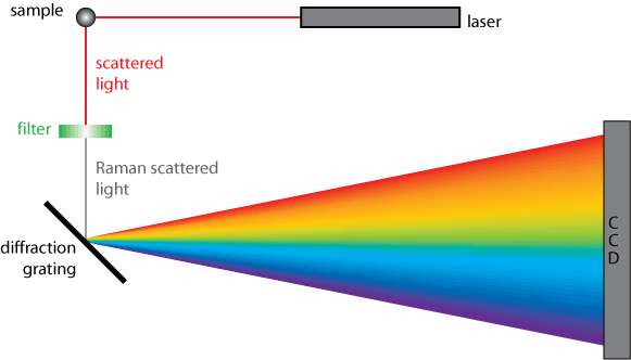
To help provide a better visualization of how Raman spectroscopy works, a generic diagram can be seen in Figure 2. A sample is irradiated with monochromatic laser light; which is then scattered by the sample. The scattered light passes through a filter to remove any stray light that may have also been scattered by the sample.2 The filtered light is then dispersed by the diffraction grating and collected on the detector. This set-up works for both the non-resonance and resonance Raman techniques.

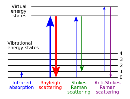
Non-resonance Raman scattering occurs when the radiation interacts with a molecule resulting in polarization of the molecule’s electrons.4 The increase in energy from the radiation excites the electrons to an unstable virtual state; therefore, the interaction is almost immediately discontinued and the radiation is emitted (scattered) at a slightly different energy than the incident radiation.4
Resonance Raman scattering occurs in a similar fashion. However, the incident radiation is at a frequency near the frequency of an electronic transition of the molecule of interest. This provides enough energy to excite the electrons to a higher electronic state. Figure 1 provides a visual depiction of what non-resonance and resonance Raman scattering looks like in terms of energy levels.

Advantages of Non-Resonance and Resonance Raman
Instrumental techniques each have certain strengths that make them better suited for some jobs as oppose to others. Non-resonance is a good example of this notion. It is considered better suited for analyzing water containing samples due to water’s low polarizability. Non-resonance and resonance Raman each have the capability to analyze samples in the gaseous, liquid, or solid state. Their non-destructive nature makes it a great candidate for doing analysis of delicate materials. Archeologists and art historians even find resonance Raman spectroscopy useful for studying and authentication of artifacts and artwork.4
Monochromatic light in the ultraviolet or near-infrared regions is generally used for both resonance and non-resonance Raman spectroscopy. A tunable laser is preferred for resonance Raman and can be an advantage. That is because only one laser is necessary to do analyses of multiples samples in which each one requires a different excitation wavelength.4 This allows the user to switch out samples without having to switch out the lasers as well. It becomes a matter of just changing the setting on the tunable laser. If the laboratory is not equipped with a tunable laser, any laser that is available can be used to achieve the enhancement of the Raman signal. The only stipulation being that the laser available must have a frequency as near as possible to one of the analyte’s electronic transitions.2 Therefore, researchers conducting resonance Raman spectroscopy without a tunable laser are at the mercy of whatever laser they do have in the laboratory.
Resonance Raman spectroscopy has greater sensitivity compared to its non-resonance counterpart. It is capable of analyzing samples with concentrations as low as 10-8 M. Non-resonance Raman can analyze samples with concentrations no lower than 0.1 M. Resonance Raman spectroscopy produces a spectrum with relatively few lines. The reason being that the technique only augments Raman signals affiliated with chromophores in the analyte.2,4 This makes the technique particularly useful for analysis of larger molecules like biomolecules.
Fluorescence Disadvantage
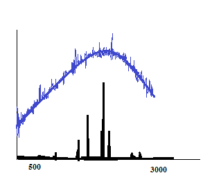
Fluorescence is a problem for both Resonance Raman techniques, particularly when using sources in the visible range.2 Non-resonance Raman signals are generally weak and can be easily overwhelmed by fluorescence signals.6 In addition, fluorescence has a longer excited state lifetime compared to Raman scattering, causing an inability to detect Raman signals.2,6 Even when the analyte is not a fluorescent molecule, the signal could be a result of the sample matrix content (i.e. solvent or contaminants). Resonance Raman is particularly at risk of inducing fluorescence because it uses sources at frequencies near to that of a molecule’s electronic transition. The radiation is more likely to absorb resulting in fluorescence as a possible mechanism for the electrons return to the ground state. Thus, highly fluorescent molecules should be avoided when using Raman spectroscopy; especially resonance Raman. Figure 3 is a general illustration of how a fluorescence signal can overwhelm Raman signals.

Raman shift (cm-1)
Figure 3: Two generic Raman spectra overlaid. The blue Raman spectrum represents one obtained via excitation source in the visible range. The black Raman spectrum represents one obtained via excitation source in the near-infrared range. The black Raman signals are free of fluorescence interference.
There are techniques that spectroscopists use to avoid fluorescence interference. For instance, background subtraction could be done. Another example is to use near-infrared radiation to excite the sample as a means to overcome fluorescence.6 A more elaborate method was used by Matousek et al. They took advantage of the differences in excitation lifetimes for Raman and fluorescence. It required implementing shifted excitation Raman difference spectroscopy (SERDS) in conjunction with a device known as a Kerr gate to successfully obtain a resonance Raman spectrum of the rhodamine 6G dye.6 SERDS is a technique that uses two excitation wavelengths to produce two Raman spectra. The excitation wavelengths have a difference in value that corresponds to the bandwidth of the Raman signal.6 The two spectra are subtracted from each other and the difference spectra is recreated by means of mathematical processes.6
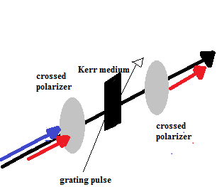
A Kerr gate can be used to remove fluorescence from a Raman signal based on their different lifetimes.6 The device consists of a couple of crossed polarizers, Kerr medium, and an additional laser to provide a gating pulse.7 Now consider a sample that has been irradiated resulting in fluorescence and Raman scattering. The fluorescence and Raman scatter would pass through the crossed polarizer and then through the Kerr medium (Matousek et al. used carbon disulfide as the Kerr medium). The Kerr gate is referred to as being open when a laser pulse (the gating pulse) strikes the Kerr medium as the fluorescence and Raman scattered light pass through.7 Furthermore, the gate remains open for a length of time corresponding to the lifetime of the Raman scatter,7 The interaction of the gating pulse with the Kerr medium causes the light to become anisotropic and transmit beyond the Kerr medium.7 The light then goes from being polarized in a linear direction to elliptical polarization. However, Raman scattered light can be selectively switched back to linear polarization by selecting the appropriate propagation length for Kerr medium transmission; or by altering the degree of anisotropy.7 The Raman scattered light is then allowed to pass through the second crossed polarizer and on to the spectrometer. Any fluorescence that passes through the Kerr medium is prevented from entering the spectrometer due to its inability to transmit through the second crossed polarizer on account of its new elliptical polarization. Figure 4 should assist with the visualization of such process.

Conclusions
This module was meant to provide an introduction to the similarities and differences between non-resonance and resonance Raman spectroscopy. Notice that they each have their own advantages making both of them powerful analytical techniques. Non-resonance Raman is more advantageous when compared to IR spectroscopy. However, resonance Raman appears to have the upper hand when compared to its non-resonance counterpart. The important thing is to choose the technique that is most appropriate for the work to be done.
Problems
- What does Dr. Nivens' quote mean and what can be done to avoid the problem?
- Archeology and art preservation were mentioned as fields in which Raman spectroscopy is useful due to the following characteristics: non-destructive to sample, qualitative analysis, and quantitative analysis. Name an additional area/field that could benefit from Raman due to these characteristics and why.
- Does non-resonance Raman or resonance Raman have a better limit of detection?
- What is polarizability?
- You are working on a project that is trying to determine if lycopene is absorbed better via supplements or diet. You only have a Raman spectrometer available to conduct your analysis. Thus you decide to determine the amount absorbed in the body by subtracting the amount excreted in urine from the total intake. In general, would it be better to detect lycopene in your biological sample using non-resonance or resonance Raman spectroscopy and why?
References
- Efremov, E.; Ariese, F.; Gooijer, C. “Achievements in resonance Raman spectroscopy: A Review of a technique with a distinct analytical chemistry potential” Analytica Chimica Acta, 606, 2008, 119-134.
- Smith, W.; Dent, G. Introduction, Basic Theory, and Principles and Resonance Raman Scattering. Modern Raman Spectroscopy, John Wiley & Sons, Ltd, England, 2005; 1-7 & 93-97.
- Schmitt, M.; Popp, J. “Raman spectroscopy at the beginning of the twenty-first century” J. Raman Spectrosc., 37, 2006, 20-28.
- Krishnan, R. S.; Shankar, R. K. “Raman effect: History of the discovery” J. Raman Spectrosc., 10, 1981, 1-8.
- Ball, D.W. “Theory of Raman Spectroscopy” Spectroscopy, 16 (11), 2001, 32.
- Matousek, P.; Towrie, M.; Parker, A. W. “Fluorescence background suppression in Raman spectroscopy using combined Kerr gated and shifted excitation Raman difference techniques” J. Raman Spectrosc., 33, 2002, 238-242.
Solutions
- "Fluorescence is the enemy of Raman" refers to the fact that fluorescence induced during Raman spectroscopy will inhibit detection of Raman signals. One way to avoid such a problem is to use an excitation source that is in the ultra-violet or near-infrared range.
- Answers will vary, but here is an example: Forensic science is a field that could benefit for the indicated characteristics of Raman spectroscopy. The non-destructive nature will insure that precious evidence is not damage or destroyed during analysis. The evidence can then be preserved for additional testing. The qualitative and quantitative factors could provide information to investigators as to what is present in their evidence (i.e. bodily fluids, drugs, accelerants, etc.).
- Resonance Raman is capable of analyte detection at concentrations as low as 10-8 M. The limit of detection is much higher for non-resonance Raman.
- Polarizability measures the capability of an applied electric field to cause a dipole moment.
- The sample will most likely contain a multitude of things because it is biological. Resonance Raman would be the better choice because lycopene contains chromophores which are targeted for excitation in that technique. Thus the spectra will not be cluttered by all the other contents in the biological sample.

