7.18: Neutron Interferometry with Polarized Spin States
- Page ID
- 141608
\( \newcommand{\vecs}[1]{\overset { \scriptstyle \rightharpoonup} {\mathbf{#1}} } \)
\( \newcommand{\vecd}[1]{\overset{-\!-\!\rightharpoonup}{\vphantom{a}\smash {#1}}} \)
\( \newcommand{\id}{\mathrm{id}}\) \( \newcommand{\Span}{\mathrm{span}}\)
( \newcommand{\kernel}{\mathrm{null}\,}\) \( \newcommand{\range}{\mathrm{range}\,}\)
\( \newcommand{\RealPart}{\mathrm{Re}}\) \( \newcommand{\ImaginaryPart}{\mathrm{Im}}\)
\( \newcommand{\Argument}{\mathrm{Arg}}\) \( \newcommand{\norm}[1]{\| #1 \|}\)
\( \newcommand{\inner}[2]{\langle #1, #2 \rangle}\)
\( \newcommand{\Span}{\mathrm{span}}\)
\( \newcommand{\id}{\mathrm{id}}\)
\( \newcommand{\Span}{\mathrm{span}}\)
\( \newcommand{\kernel}{\mathrm{null}\,}\)
\( \newcommand{\range}{\mathrm{range}\,}\)
\( \newcommand{\RealPart}{\mathrm{Re}}\)
\( \newcommand{\ImaginaryPart}{\mathrm{Im}}\)
\( \newcommand{\Argument}{\mathrm{Arg}}\)
\( \newcommand{\norm}[1]{\| #1 \|}\)
\( \newcommand{\inner}[2]{\langle #1, #2 \rangle}\)
\( \newcommand{\Span}{\mathrm{span}}\) \( \newcommand{\AA}{\unicode[.8,0]{x212B}}\)
\( \newcommand{\vectorA}[1]{\vec{#1}} % arrow\)
\( \newcommand{\vectorAt}[1]{\vec{\text{#1}}} % arrow\)
\( \newcommand{\vectorB}[1]{\overset { \scriptstyle \rightharpoonup} {\mathbf{#1}} } \)
\( \newcommand{\vectorC}[1]{\textbf{#1}} \)
\( \newcommand{\vectorD}[1]{\overrightarrow{#1}} \)
\( \newcommand{\vectorDt}[1]{\overrightarrow{\text{#1}}} \)
\( \newcommand{\vectE}[1]{\overset{-\!-\!\rightharpoonup}{\vphantom{a}\smash{\mathbf {#1}}}} \)
\( \newcommand{\vecs}[1]{\overset { \scriptstyle \rightharpoonup} {\mathbf{#1}} } \)
\( \newcommand{\vecd}[1]{\overset{-\!-\!\rightharpoonup}{\vphantom{a}\smash {#1}}} \)
\(\newcommand{\avec}{\mathbf a}\) \(\newcommand{\bvec}{\mathbf b}\) \(\newcommand{\cvec}{\mathbf c}\) \(\newcommand{\dvec}{\mathbf d}\) \(\newcommand{\dtil}{\widetilde{\mathbf d}}\) \(\newcommand{\evec}{\mathbf e}\) \(\newcommand{\fvec}{\mathbf f}\) \(\newcommand{\nvec}{\mathbf n}\) \(\newcommand{\pvec}{\mathbf p}\) \(\newcommand{\qvec}{\mathbf q}\) \(\newcommand{\svec}{\mathbf s}\) \(\newcommand{\tvec}{\mathbf t}\) \(\newcommand{\uvec}{\mathbf u}\) \(\newcommand{\vvec}{\mathbf v}\) \(\newcommand{\wvec}{\mathbf w}\) \(\newcommand{\xvec}{\mathbf x}\) \(\newcommand{\yvec}{\mathbf y}\) \(\newcommand{\zvec}{\mathbf z}\) \(\newcommand{\rvec}{\mathbf r}\) \(\newcommand{\mvec}{\mathbf m}\) \(\newcommand{\zerovec}{\mathbf 0}\) \(\newcommand{\onevec}{\mathbf 1}\) \(\newcommand{\real}{\mathbb R}\) \(\newcommand{\twovec}[2]{\left[\begin{array}{r}#1 \\ #2 \end{array}\right]}\) \(\newcommand{\ctwovec}[2]{\left[\begin{array}{c}#1 \\ #2 \end{array}\right]}\) \(\newcommand{\threevec}[3]{\left[\begin{array}{r}#1 \\ #2 \\ #3 \end{array}\right]}\) \(\newcommand{\cthreevec}[3]{\left[\begin{array}{c}#1 \\ #2 \\ #3 \end{array}\right]}\) \(\newcommand{\fourvec}[4]{\left[\begin{array}{r}#1 \\ #2 \\ #3 \\ #4 \end{array}\right]}\) \(\newcommand{\cfourvec}[4]{\left[\begin{array}{c}#1 \\ #2 \\ #3 \\ #4 \end{array}\right]}\) \(\newcommand{\fivevec}[5]{\left[\begin{array}{r}#1 \\ #2 \\ #3 \\ #4 \\ #5 \\ \end{array}\right]}\) \(\newcommand{\cfivevec}[5]{\left[\begin{array}{c}#1 \\ #2 \\ #3 \\ #4 \\ #5 \\ \end{array}\right]}\) \(\newcommand{\mattwo}[4]{\left[\begin{array}{rr}#1 \amp #2 \\ #3 \amp #4 \\ \end{array}\right]}\) \(\newcommand{\laspan}[1]{\text{Span}\{#1\}}\) \(\newcommand{\bcal}{\cal B}\) \(\newcommand{\ccal}{\cal C}\) \(\newcommand{\scal}{\cal S}\) \(\newcommand{\wcal}{\cal W}\) \(\newcommand{\ecal}{\cal E}\) \(\newcommand{\coords}[2]{\left\{#1\right\}_{#2}}\) \(\newcommand{\gray}[1]{\color{gray}{#1}}\) \(\newcommand{\lgray}[1]{\color{lightgray}{#1}}\) \(\newcommand{\rank}{\operatorname{rank}}\) \(\newcommand{\row}{\text{Row}}\) \(\newcommand{\col}{\text{Col}}\) \(\renewcommand{\row}{\text{Row}}\) \(\newcommand{\nul}{\text{Nul}}\) \(\newcommand{\var}{\text{Var}}\) \(\newcommand{\corr}{\text{corr}}\) \(\newcommand{\len}[1]{\left|#1\right|}\) \(\newcommand{\bbar}{\overline{\bvec}}\) \(\newcommand{\bhat}{\widehat{\bvec}}\) \(\newcommand{\bperp}{\bvec^\perp}\) \(\newcommand{\xhat}{\widehat{\xvec}}\) \(\newcommand{\vhat}{\widehat{\vvec}}\) \(\newcommand{\uhat}{\widehat{\uvec}}\) \(\newcommand{\what}{\widehat{\wvec}}\) \(\newcommand{\Sighat}{\widehat{\Sigma}}\) \(\newcommand{\lt}{<}\) \(\newcommand{\gt}{>}\) \(\newcommand{\amp}{&}\) \(\definecolor{fillinmathshade}{gray}{0.9}\)The following paragraph appears in an encyclopedia entry on neutron optics.(1) A description of the original experiment is available in the physics research literature. (2) It is the purpose of this tutorial to work through the quantum math of the neutron interferometry experiment described here.
One of the most important properties of quantum theory is the superposition principle, according to which the wave functions of coherent states combine additively. One of the most simple, yet most profound examples of this involves the spin for spin-½ particles. Such particles have two spin states, spin “up” (spin is directed upward along the z axis, sz = + ½), and spin “down” (sz = −½). If the z component of spin is measured, it is found that the particle is either spin up or spin down. Yet a spin along the x axis can be described as a linear combination of these two states. By a judicious use of magnetic fields, the neutron was polarized so that it was spin up in one leg of the interferometer and spin down in the other. Then when these two beams of equal amplitude, each polarized along the z axis, were recombined after passing through the interferometer, it was seen that they were polarized in the x-y plane, exactly according to the laws of quantum theory. This polarization was perpendicular to that of either of the beams separately, which proved both the coherence of the beam and the superposition principle for spin. This is the first time a beam of spin-½ particles has ever been spatially separated and then coherently recombined in this fashion.
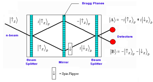
The figure shows a simplified schematic of the neutron interferometer and the spin states of the neutron in each leg of the interferometer. The labels U and D refer to the upper and lower arms of the interferometer. The interferometer is fabricated out of a perfect single crystal and the Bragg planes of the crystal function as beam splitters, permitting both transmission and reflection. The middle element, which is labeled as a mirror, is actually another beam splitter; the neutrons transmitted in the upper and lower arms are discarded. The following conventions and simplifications are adopted:
- It is assumed that the diagram describes the history of an individual neutron.
- The paths to the detectors are of equal distance, meaning that the neutron beam is recombined at the final beam splitter in such a way that the labels U and D become meaningless at the detectors. They are retained in the diagram so the reader can more readily follow the math.
- At the beam splitters reflection is assigned a 90° (= π/2 = i) phase shift relative to transmission. (Reminder; the mirror is actually another beam splitter.)
- In the interest of mathematical economy normalization constants are omitted.
In this experiment neutrons polarized spin-up in the z-direction illuminate a beam splitter creating a superposition of being transmitted (D) and reflected (U). A second beam splitter (mirror) redirects the beam to a third beam splitter which recombines the D and U branches before detection at A and B. But prior to recombination, the lower branch spin state is flipped to spin-down in the z-direction. Recombination at the final beam splitter leads to the superposition states at A and B shown in the figure below.

It is easy to show that these superposition states at A and B are actually spin-down and spin-up in the x-direction. This is because x-direction spin states can be written as linear superpositions of the z-direction spin states. As previously, normalization constants are omitted.
\[ | \uparrow_x \rangle = | \uparrow_z \rangle + | \downarrow_z rangle \nonumber \]
and
\[ | \downarrow_x \rangle = - | \uparrow_z \rangle + | \downarrow_z rangle \nonumber \]
Using these superpositions it is easy to show that the detected spin polarizations are \( | \downarrow_x \rangle\) at A and \( | \uparrow_x \rangle\) at B.
\[ |A \rangle = i | \downarrow_x \rangle \nonumber \]
and
\[ |B \rangle = - | \uparrow_x \rangle \nonumber \]
In summary, this experiment is a “textbook” illustration of the quantum mechanical superposition principle.
References
- Daniel M. Greenberger, "Neutron optics", in AccessScience@McGraw-Hill, http://www.accessscience.com, DOI 10.1036/1097-8542.451000.
- J. Summhammer, et al. “Direct observation of fermion spin superposition by neutron interferometry,” Physical Review A. 27, 2523-2532 (1983).

