7.7: Mach-Zehner Polarization Interferometer Analyzed Using Tensor Algebra
- Page ID
- 137863
\( \newcommand{\vecs}[1]{\overset { \scriptstyle \rightharpoonup} {\mathbf{#1}} } \)
\( \newcommand{\vecd}[1]{\overset{-\!-\!\rightharpoonup}{\vphantom{a}\smash {#1}}} \)
\( \newcommand{\dsum}{\displaystyle\sum\limits} \)
\( \newcommand{\dint}{\displaystyle\int\limits} \)
\( \newcommand{\dlim}{\displaystyle\lim\limits} \)
\( \newcommand{\id}{\mathrm{id}}\) \( \newcommand{\Span}{\mathrm{span}}\)
( \newcommand{\kernel}{\mathrm{null}\,}\) \( \newcommand{\range}{\mathrm{range}\,}\)
\( \newcommand{\RealPart}{\mathrm{Re}}\) \( \newcommand{\ImaginaryPart}{\mathrm{Im}}\)
\( \newcommand{\Argument}{\mathrm{Arg}}\) \( \newcommand{\norm}[1]{\| #1 \|}\)
\( \newcommand{\inner}[2]{\langle #1, #2 \rangle}\)
\( \newcommand{\Span}{\mathrm{span}}\)
\( \newcommand{\id}{\mathrm{id}}\)
\( \newcommand{\Span}{\mathrm{span}}\)
\( \newcommand{\kernel}{\mathrm{null}\,}\)
\( \newcommand{\range}{\mathrm{range}\,}\)
\( \newcommand{\RealPart}{\mathrm{Re}}\)
\( \newcommand{\ImaginaryPart}{\mathrm{Im}}\)
\( \newcommand{\Argument}{\mathrm{Arg}}\)
\( \newcommand{\norm}[1]{\| #1 \|}\)
\( \newcommand{\inner}[2]{\langle #1, #2 \rangle}\)
\( \newcommand{\Span}{\mathrm{span}}\) \( \newcommand{\AA}{\unicode[.8,0]{x212B}}\)
\( \newcommand{\vectorA}[1]{\vec{#1}} % arrow\)
\( \newcommand{\vectorAt}[1]{\vec{\text{#1}}} % arrow\)
\( \newcommand{\vectorB}[1]{\overset { \scriptstyle \rightharpoonup} {\mathbf{#1}} } \)
\( \newcommand{\vectorC}[1]{\textbf{#1}} \)
\( \newcommand{\vectorD}[1]{\overrightarrow{#1}} \)
\( \newcommand{\vectorDt}[1]{\overrightarrow{\text{#1}}} \)
\( \newcommand{\vectE}[1]{\overset{-\!-\!\rightharpoonup}{\vphantom{a}\smash{\mathbf {#1}}}} \)
\( \newcommand{\vecs}[1]{\overset { \scriptstyle \rightharpoonup} {\mathbf{#1}} } \)
\(\newcommand{\longvect}{\overrightarrow}\)
\( \newcommand{\vecd}[1]{\overset{-\!-\!\rightharpoonup}{\vphantom{a}\smash {#1}}} \)
\(\newcommand{\avec}{\mathbf a}\) \(\newcommand{\bvec}{\mathbf b}\) \(\newcommand{\cvec}{\mathbf c}\) \(\newcommand{\dvec}{\mathbf d}\) \(\newcommand{\dtil}{\widetilde{\mathbf d}}\) \(\newcommand{\evec}{\mathbf e}\) \(\newcommand{\fvec}{\mathbf f}\) \(\newcommand{\nvec}{\mathbf n}\) \(\newcommand{\pvec}{\mathbf p}\) \(\newcommand{\qvec}{\mathbf q}\) \(\newcommand{\svec}{\mathbf s}\) \(\newcommand{\tvec}{\mathbf t}\) \(\newcommand{\uvec}{\mathbf u}\) \(\newcommand{\vvec}{\mathbf v}\) \(\newcommand{\wvec}{\mathbf w}\) \(\newcommand{\xvec}{\mathbf x}\) \(\newcommand{\yvec}{\mathbf y}\) \(\newcommand{\zvec}{\mathbf z}\) \(\newcommand{\rvec}{\mathbf r}\) \(\newcommand{\mvec}{\mathbf m}\) \(\newcommand{\zerovec}{\mathbf 0}\) \(\newcommand{\onevec}{\mathbf 1}\) \(\newcommand{\real}{\mathbb R}\) \(\newcommand{\twovec}[2]{\left[\begin{array}{r}#1 \\ #2 \end{array}\right]}\) \(\newcommand{\ctwovec}[2]{\left[\begin{array}{c}#1 \\ #2 \end{array}\right]}\) \(\newcommand{\threevec}[3]{\left[\begin{array}{r}#1 \\ #2 \\ #3 \end{array}\right]}\) \(\newcommand{\cthreevec}[3]{\left[\begin{array}{c}#1 \\ #2 \\ #3 \end{array}\right]}\) \(\newcommand{\fourvec}[4]{\left[\begin{array}{r}#1 \\ #2 \\ #3 \\ #4 \end{array}\right]}\) \(\newcommand{\cfourvec}[4]{\left[\begin{array}{c}#1 \\ #2 \\ #3 \\ #4 \end{array}\right]}\) \(\newcommand{\fivevec}[5]{\left[\begin{array}{r}#1 \\ #2 \\ #3 \\ #4 \\ #5 \\ \end{array}\right]}\) \(\newcommand{\cfivevec}[5]{\left[\begin{array}{c}#1 \\ #2 \\ #3 \\ #4 \\ #5 \\ \end{array}\right]}\) \(\newcommand{\mattwo}[4]{\left[\begin{array}{rr}#1 \amp #2 \\ #3 \amp #4 \\ \end{array}\right]}\) \(\newcommand{\laspan}[1]{\text{Span}\{#1\}}\) \(\newcommand{\bcal}{\cal B}\) \(\newcommand{\ccal}{\cal C}\) \(\newcommand{\scal}{\cal S}\) \(\newcommand{\wcal}{\cal W}\) \(\newcommand{\ecal}{\cal E}\) \(\newcommand{\coords}[2]{\left\{#1\right\}_{#2}}\) \(\newcommand{\gray}[1]{\color{gray}{#1}}\) \(\newcommand{\lgray}[1]{\color{lightgray}{#1}}\) \(\newcommand{\rank}{\operatorname{rank}}\) \(\newcommand{\row}{\text{Row}}\) \(\newcommand{\col}{\text{Col}}\) \(\renewcommand{\row}{\text{Row}}\) \(\newcommand{\nul}{\text{Nul}}\) \(\newcommand{\var}{\text{Var}}\) \(\newcommand{\corr}{\text{corr}}\) \(\newcommand{\len}[1]{\left|#1\right|}\) \(\newcommand{\bbar}{\overline{\bvec}}\) \(\newcommand{\bhat}{\widehat{\bvec}}\) \(\newcommand{\bperp}{\bvec^\perp}\) \(\newcommand{\xhat}{\widehat{\xvec}}\) \(\newcommand{\vhat}{\widehat{\vvec}}\) \(\newcommand{\uhat}{\widehat{\uvec}}\) \(\newcommand{\what}{\widehat{\wvec}}\) \(\newcommand{\Sighat}{\widehat{\Sigma}}\) \(\newcommand{\lt}{<}\) \(\newcommand{\gt}{>}\) \(\newcommand{\amp}{&}\) \(\definecolor{fillinmathshade}{gray}{0.9}\)The purpose of this tutorial is to analyze a Mach-Zehnder (MZ) interferometer with polarizing beam splitters (PBS) using tensor algebra. First we will review the traditional MZ with non-polarizing beam splitters using matrix algebra.

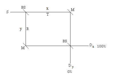
The source emits photons in the x-direction illuminating a 50-50 beam splitter which splits the beam into a superposition of motion in the x- and y-directions. The reflected beam collects a \( \frac{ \pi}{2}\) (i) phase shift relative to the transmitted beam. Mirrors redirect the two beams to a second 50-50 BS. For the ideal case of an equal arm interferometer the photons are always registered at Dx and never at Dy. One way to explain this is shown on the figure above. Each photon has two paths to each of the detectors. At Dx the photon's paths add in phase each being shifted by \( \frac{ \pi}{2}\), resulting in constructive interference. At Dy the photon's paths are 180 degrees out of phase causing destructive interference.
The matrix analysis requires vectors to represent photon states, direction of propagation and polarization, and matrices to represent the devices that the photon interacts with, such as beam splitters and mirrors. The vectors representing direction of propagation are,
\[ x = \begin{pmatrix}
1\\
0
\end{pmatrix} ~~~ y = \begin{pmatrix}
0\\
1
\end{pmatrix} \nonumber \]
The beam splitters and mirrors are represented by the following matrices which operate on the motional states.
\[ BS = \frac{1}{ \sqrt{2}} \begin{pmatrix}
1 & i\\
i & 1
\end{pmatrix} ~~~ M = \begin{pmatrix}
0 & 1\\
1 & 0
\end{pmatrix} \nonumber \]
The probability that the photon will be moving in the x-direction after the second BS and therefore detected at Dx is 1. The probability it will be registered at Dy is 0.
\[ \big( | x^T BS(M)BS(x) | \big) ^2 = 1 ~~~ \big( | y^T BS(M)BS(x) | \big) ^2 = 0 \nonumber \]
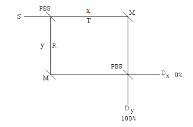
In a polarization MZ interferometer the traditional beam splitters are replaced with polarizing beam splitters, which in this case transmit horizontal polarization and reflect vertical polarization.

Now in addition the direction of propagation, the photons have a polarization state which is initially restricted to horizontal or vertical polarization.
\[ h = \begin{pmatrix}
1\\
0
\end{pmatrix} ~~~ v = \begin{pmatrix}
0\\
1
\end{pmatrix} \nonumber \]
There are now four photon states: |xh>, |xv>, |yh> and |yv>, which can also be written |x>|h>, |x>|v>, |y>|h> and |y>|v>. These are vector tensor products and they take us from the two-dimensional space of the previous example to a four-dimensional Hilbert space.
\[ |xh \rangle = |x \rangle |h \rangle = \begin{pmatrix}
1\\
0
\end{pmatrix} \otimes \begin{pmatrix}
1\\
0
\end{pmatrix} = \begin{pmatrix}
1\\
0\\
0\\
0
\end{pmatrix} ~~~ |xv \rangle = |x \rangle |v \rangle = \begin{pmatrix}
1\\
0
\end{pmatrix} \otimes \begin{pmatrix}
0\\
1
\end{pmatrix} = \begin{pmatrix}
0\\
1\\
0\\
0
\end{pmatrix} \nonumber \]
\[ |yh \rangle = |y \rangle |h \rangle = \begin{pmatrix}
0\\
1
\end{pmatrix} \otimes \begin{pmatrix}
1\\
0
\end{pmatrix} = \begin{pmatrix}
0\\
0\\
1\\
0
\end{pmatrix} ~~~ |yv \rangle = |y \rangle |v \rangle = \begin{pmatrix}
0\\
1
\end{pmatrix} \otimes \begin{pmatrix}
0\\
1
\end{pmatrix} = \begin{pmatrix}
0\\
0\\
0\\
1
\end{pmatrix} \nonumber \]
\[ xh = \begin{pmatrix}
1\\
0\\
0\\
0
\end{pmatrix} ~~~ xv = \begin{pmatrix}
0\\
1\\
0\\
0
\end{pmatrix} ~~~ yh = \begin{pmatrix}
0\\
0\\
1\\
0
\end{pmatrix} ~~~ yv = \begin{pmatrix}
0\\
0\\
0\\
1
\end{pmatrix} \nonumber \]
As mentioned previously the PBS transmits horizontal polarization and reflects vertical polarization. Unlike the nonpolarizing BS, there is no phase change on reflection. The matrix representing a PBS can be constructed by considering the fate of the individual photon states encountering a PBS.
\[ \widehat{PBS} = |xh \rangle \langle xh | + |yv \rangle \langle xv | + | yh \rangle \langle yh | + | xv \rangle \langle yv | \nonumber \]
\[ PBS: \begin{pmatrix}
1\\
0\\
0\\
0
\end{pmatrix} \begin{pmatrix}
1 & 0 & 0 & 0
\end{pmatrix} + \begin{pmatrix}
0\\
0\\
0\\
1
\end{pmatrix} \begin{pmatrix}
0 & 1 & 0 & 0
\end{pmatrix} + \begin{pmatrix}
0\\
0\\
1\\
0
\end{pmatrix} \begin{pmatrix}
0 & 0 & 1 & 0
\end{pmatrix} + \begin{pmatrix}
0\\
1\\
0\\
0
\end{pmatrix} \begin{pmatrix}
0 & 0 & 0 & 1
\end{pmatrix} \nonumber \]
\[ PBS = \begin{pmatrix}
1 & 0 & 0 & 0\\
0 & 0 & 0 & 1\\
0 & 0 & 1 & 0\\
0 & 1 & 0& 0
\end{pmatrix} \nonumber \]
This gives us the PBS operator in the four-dimensional Hilbert space. Next we construct the matrix for the mirror in this space. The matrices representing the various photon interactions must be 4x4 because the photon vector states are 1x4. The mirror only affects the direction of propagation and not the polarization state of the photon. Since the motional state appears first in the kets, we form the 4-D mirror matrix by the following tensor (Kronecker) product of M and the identity matrix.
\[ \widehat{M}' = \widehat{M} \otimes \widehat{I} = \begin{pmatrix}
0 & 0 & 1 & 0\\
0 & 0 & 0 & 1\\
1 & 0 & 0 & 0\\
0 & 1 & 0& 0
\end{pmatrix} \nonumber \]
\[ M' = kronecker \bigg[ M, \begin{pmatrix}
1 & 0 \\
0 & 1
\end{pmatrix} \bigg] ~~~ M' = \begin{pmatrix}
0 & 0 & 1 & 0\\
0 & 0 & 0 & 1\\
1 & 0 & 0 & 0\\
0 & 1 & 0& 0
\end{pmatrix} \nonumber \]
As constructed this matrix changes the photon's direction of propagation with out affecting its state of polarization.
Now suppose that the source emits a horizontally polarized photon, |xh>. Calculation shows that it arrives at Dy with horizontal polarization,|yh>, 100% of the time.
\[ \big( | yh^T PBS(M')PBS(xh) | \big) ^2 = 1 \nonumber \]
If the source emits a vertically polarized photon, |xv>. Calculation shows that it arrives at Dy with vertical polarization,|yv>, 100% of the time.
\[ \big( | yv^T PBS(M')PBS(xv) | \big) ^2 = 1 \nonumber \]
A photon emitted by the source polarized at an angle of \( \theta\) relative to the horizontal has the following state vector.
\[ |x \theta \rangle = \begin{pmatrix}
1\\
0
\end{pmatrix} \otimes \begin{pmatrix}
\cos \theta\\
\sin \theta
\end{pmatrix} = \begin{pmatrix}
\cos \theta\\
\sin \theta\\
0\\
0
\end{pmatrix} \nonumber \]
It is easy to show that in the MZ polarization interferometer, the polarization state of the source photon is preserved while the direction of propagation changes.
\[ |y \theta \rangle = \begin{pmatrix}
0\\
1
\end{pmatrix} \otimes \begin{pmatrix}
\cos \theta\\
\sin \theta
\end{pmatrix} = \begin{pmatrix}
0 \\
0 \\
\cos \theta \\
\sin \theta
\end{pmatrix} \nonumber \]
\[ \big| \rangle y \theta | \widehat{PBS} \widehat{M'} \widehat{PBS} | x \theta \rangle \big|^2 = 1 \nonumber \]
\[ \Bigg[ \Bigg| \begin{pmatrix}
0 & 0 & \cos \theta & \sin \theta
\end{pmatrix} \begin{pmatrix}
1 & 0 & 0 & 0\\
0 & 0 & 0 & 1\\
0 & 0 & 1 & 0\\
0 & 1 & 0 & 0
\end{pmatrix} \begin{pmatrix}
0 & 0 & 1 & 0\\
0 & 0 & 0 & 1\\
1 & 0 & 0 & 0\\
0 & 1 & 0 & 0
\end{pmatrix} \begin{pmatrix}
1 & 0 & 0 & 0\\
0 & 0 & 0 & 1\\
0 & 0 & 1 & 0\\
0 & 1 & 0 & 0
\end{pmatrix} \begin{pmatrix}
\cos \theta \\
\sin \theta\\
0\\
0
\end{pmatrix} \Bigg| \Bigg]^2 simplify \rightarrow 1 \nonumber \]
This is an excellent example of the superposition principle. The first PBS creates a x-h, y-v superposition state.
\[ \begin{pmatrix}
1 & 0 & 0 & 0\\
0 & 0 & 0 & 1\\
0 & 0 & 1 & 0\\
0 & 1 & 0 & 0
\end{pmatrix} \begin{pmatrix}
\cos \theta \\
\sin \theta\\
0\\
0
\end{pmatrix} \rightarrow \begin{pmatrix}
\cos \theta \\
0 \\
0\\
\sin \theta
\end{pmatrix} \nonumber \]
\[ \begin{pmatrix}
1\\
0
\end{pmatrix} \begin{pmatrix}
\cos \theta\\
0
\end{pmatrix} + \begin{pmatrix}
0\\
1
\end{pmatrix} \begin{pmatrix}
0\\
\sin \theta
\end{pmatrix} = \begin{pmatrix}
\cos \theta\\
0\\
0\\
\sin \theta
\end{pmatrix} \nonumber \]
The mirror changes this to a y-h, x-v superposition.
\[ \begin{pmatrix}
0 & 0 & 1 & 0\\
0 & 0 & 0 & 1\\
1 & 0 & 0 & 0\\
0 & 1 & 0 & 0
\end{pmatrix} \begin{pmatrix}
\cos \theta \\
0 \\
0\\
\sin \theta
\end{pmatrix} \rightarrow \begin{pmatrix}
0 \\
\sin \theta \\
\cos \theta \\
0
\end{pmatrix} \nonumber \]
\[ \begin{pmatrix}
0\\
1
\end{pmatrix} \begin{pmatrix}
\cos \theta\\
0
\end{pmatrix} + \begin{pmatrix}
1\\
0
\end{pmatrix} \begin{pmatrix}
0\\
\sin \theta
\end{pmatrix} = \begin{pmatrix}
0\\
\sin \theta\\
\cos \theta\\
0
\end{pmatrix} \nonumber \]
The second PBS restores the original polarization state, but changes the direction of propagation.
\[ \begin{pmatrix}
1 & 0 & 0 & 0\\
0 & 0 & 0 & 1\\
0 & 0 & 1 & 0\\
0 & 1 & 0 & 0
\end{pmatrix} \begin{pmatrix}
0 \\
\sin \theta \\
\cos \theta \\
0
\end{pmatrix} \rightarrow \begin{pmatrix}
0 \\
0 \\
\cos \theta \\
\sin \theta
\end{pmatrix} \nonumber \]
\[ \begin{pmatrix}
0\\
1
\end{pmatrix} \begin{pmatrix}
\cos \theta\\
0
\end{pmatrix} + \begin{pmatrix}
0\\
1
\end{pmatrix} \begin{pmatrix}
0\\
\sin \theta
\end{pmatrix} = \begin{pmatrix}
0\\
1
\end{pmatrix} \begin{pmatrix}
\cos \theta\\
\sin \theta
\end{pmatrix} = \begin{pmatrix}
0\\
0\\
\cos \theta\\
\sin \theta
\end{pmatrix} \nonumber \]

