13.4.2: Ligands similar to CO
- Page ID
- 391851
Now let us leave the \(\ce{CO}\) ligand, consider a number of related ligands, and discuss similarities and differences compared to the \(\ce{CO}\) ligand.
The cyano ligand (CN-)
Let us start with the cyano ligand \(\ce{CN^-}\). This ligand is isoelectronic to the \(\ce{CO}\) ligand. The N atom has one electron less than O, but the negative charge at the cyanide ligand compensates for that. One question we can ask is: What is the reactive end? The answer is: In analogy to the carbonyl ligand the reactive end is the carbon atom. We can explain this by the fact that the MO diagram is similar to that of \(\ce{CO}\), only the differences in atomic orbital energies are smaller due to the smaller electronegativity difference between C and N compared to C and O. Therefore, like in \(\ce{CO}\), the HOMO is represented by the electron lone pair at the C, which makes C the more reactive end. Due to the smaller electronegativity difference, the difference in energy between the lone pair at C and the lone pair at N is smaller, therefore, in contrast to \(\ce{CO}\), the cyano ligand acts far more often as a bridging ligand between two metals using both of its electron lone pairs.
Would we expect the cyano ligand to be a stronger or weaker \(\sigma\)-donor compared to the \(\ce{CO}\) ligand? Think about it for a moment. The answer is: It is a stronger \(\sigma\)-donor because of its negative charge. The negative charge at the ligand increases electrostatic repulsion between the electrons, and this increases the orbital energies. Therefore, there is a stronger tendency to donate the electrons. Our next question is: Is the \(\ce{CN^-}\) ligand a stronger or weaker \(\pi\)-acceptor than \(\ce{CO}\)? The energy of the \(\pi^*\)-orbitals is higher compared to \(\ce{CO}\) because of the negative charge at the ligand. Because of that, electrons from the metal cannot be as easily accepted by the ligand. Therefore, the cyano ligand is a weaker \(\pi\)-acceptor than the carbonyl ligand. Our last question is: Are cyano complexes more stable with metals in high or low oxidation states. Because of electrostatic arguments a cyanide anion interacts more strongly with a metal cation rather than a metal in a zero or negative oxidation state. Therefore, unlike \(\ce{CO}\), \(\ce{CN^-}\) does not stabilize metals in low oxidation states. It prefers to make complexes with metal in high, positive oxidation numbers.
The Nitrosyl Ligand NO
The nitrosyl ligand \(\ce{NO}\) is another ligand similar to \(\ce{CO}\). It has one more electron that \(\ce{CO}\) because N has one more electron than C. The additional electron makes \(\ce{NO}\) an “odd” molecule with a radical electron. Like in \(\ce{CO}\) and \(\ce{CN^-}\), the more electropositive element is the reactive end. In the case of \(\ce{NO}\) it is the N atom. The radical electron is the most reactive electron that can be most easily donated, however the electron lone pair at N may be donated in addition. In the former case, the \(\ce{NO}\) is a 1-electron donor, in the latter it is a 3-electron donor. How can we tell if one or three electrons have been donated? When only one electron is donated, the electron lone pair at the nitrogen is sterically active and leads to a bent structure (Fig. \(\PageIndex{1}\)).

An example is the trans-bis-(ethylenediamine)chloronitrosyl cobalt (1+) cation. Generally, the \(\ce{O-N-M}\) bond angle in nitrosyl complexes with \(\ce{NO}\) as a 1e-donor can vary between 119 and 140°. We can also identify a bent nitrosyl ligand in the IR spectrum. Typical wave numbers are 1520-1729 cm-1.

When the nitrosyl ligand donates all three electrons, then it binds to the metal in a linear fashion (Fig. \(\PageIndex{2}\)). The electron lone pair is no longer sterically active because it is involved in the bonding. An example is the nitroprusside anion \(\ce{[Fe(CN)5(NO)]^2-}\). It is used as a medication for the treatment of high blood pressure. The bond angles in complexes with \(\ce{NO}\) as the 3-electron donor are often not exactly 180°, but vary between 165 and 180°. It can also be identified in the IR because it has a characteristic band between 1610-1680 cm-1.
There is a also a different view on nitrosyl complexes with linear and bent structures. In bent structures we can also consider the ligand as an \(\ce{NO^-}\) anion that donates two electrons. The \(\ce{NO^-}\) anion has two electron lone pairs at N. When it donates two electrons then one sterically active electron lone pair remains at the nitrogen atom. In linear structures we can regard the ligand also as an \(\ce{NO^+}\) cation that donates two electrons. An \(\ce{NO^+}\) cation has one electron lone pair at N, and when it donates that lone pair then there is no sterically active electron at the nitrogen left, and thus the ligand binds in a linear fashion.
We could also ask: What can neutral \(\ce{NO}\) not be a 2-electron donor with the radical electron left at N? The answer is: The radical electron is the highest energy electron, and is always used first in interactions with a metal.
Phosphine Ligands
Phosphines are most notable for their remarkable electronic and steric tunability and their “innocence”—they tend to avoid participating directly in organometallic reactions, but have the ability to profoundly modulate the electronic properties of the metal center to which they’re bound. Furthermore, because the energy barrier to umbrella flipping of phosphines is quite high, “chiral-at-phosphorus” ligands can be isolated in enantioenriched form and introduced to metal centers, bringing asymmetry just about as close to the metal as it can get in chiral complexes. Phosphorus NMR is a technique that Just Works (thanks, nature). Soft phosphines match up very well with the soft low-valent transition metals. Electron-poor phosphines are even good π-acids!
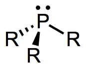
Like CO, phosphines are dative, L-type ligands that formally contribute two electrons to the metal center. Unlike CO, most phosphines are not small enough to form more than four bonds to a single metal center (and for large R, the number is even smaller). Steric hindrance becomes a problem when five or more PR3 ligands try to make their way into the space around the metal. An interesting consequence of this fact is that many phosphine-containing complexes do not possess 18 valence electrons. Examples include Pt(PCy3)2, Pd[P(t-Bu)3]2, and [Rh(PPh3)3]+. Doesn’t that just drive you crazy? It drives the complexes crazy as well—and most of these coordinatively unsaturated compounds are wonderful catalysts.
Bridging by phosphines is extremely rare, but ligands containing multiple phosphine donors that bind in an Ln (n > 1) fashion to a single metal center are all over the place. These ligands are called chelating or polydentate to indicate that they latch on to metal centers through multiple binding sites. For entropic reasons, chelating ligands bind to a single metal center at multiple points if possible, instead of attaching to two different metal centers (the aptly named chelate effect). An important characteristic of chelating phosphines is bite angle, defined as the predominant P–M–P angle in known complexes of the ligand. We’ll get into the interesting effects of bite angle later, but for now, we might imagine how “unhappy” a ligand with a preferred bite angle of 120° would be in the square planar geometry. It would much rather prefer to be part of a trigonal bipyramidal complex, for instance.
The predominant orbital interaction contributing to phosphine binding is the one we expect, a lone pair on phosphorus interacting with an empty metallic d orbital. The electronic nature of the R groups influences the electron-donating ability of the phosphorus atom. For instance, alkylphosphines, which possess P–Csp3 bonds, tend to be better electron donors than arylphosphines, which possess P–Csp2 bonds. The rationale here is the greater electronegativity of the sp2 hybrid orbital versus the sp3 hybrid, which causes the phosphorus atom to hold more tightly to its lone pair when bound to an sp2 carbon. The same idea applies when electron-withdrawing and -donating groups are incorporated into R: the electron density on P is low when R contains electron-withdrawing groups and high when R contains electron-donating groups. Ligands (and associated metals) in the former class are called electron poor, while those in the latter class are electron rich.
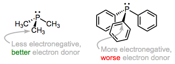
As we add electronegative R groups, the phosphorus atom (and the metal to which it's bound) become more electron poor.
Like CO, phosphines participate in backbonding to a certain degree; however, the phenomenon here is of a fundamentally different nature than CO backbonding. For one thing, phosphines lack a π* orbital. In the days of yore, chemists attributed backbonding in phosphine complexes to an interaction between a metallic dπ orbital and an empty 3d orbital on phosphorus. However, this idea has elegantly been proven bogus, and a much more organicker-friendly explanation has taken its place (no d orbitals on P required!). In an illuminating series of experiments, M–P and P–R bond lengths were measured via crystallography for several redox pairs of complexes. I’ve chosen two illustrative examples, although the linked reference is chock full of other pairs. The question is: how do we explain the changes in bond length upon oxidation?

Upon oxidation, M–P bond lengths increase and and P–R bond lengths decrease. Why?
Oxidation decreases the ability of the metal to backbond, because it removes electron density from the metal. This explains the increases in M–P bond length—just imagine a decrease the M–P bond order due to worse backbonding. And the decrease in P–R bond length? It’s important to see that invoking only the phosphorus 3d orbitals would not explain changes in the P–R bond lengths, as the 3d atomic orbitals are most definitely localized on phosphorus. Instead, we must invoke the participation of σ*P–R orbitals in phosphine backbonding to account for the P–R length decreases. When all is said and done, the LUMO of the free phosphine has mostly P–R antibonding character, with some 3d thrown into the mix. The figure below depicts one of the interactions involved in M–P backbonding, a dπ → σ* interaction (an orthogonal dπ → σ* interaction also plays a role). As with CO, a resonance structure depicting an M=P double bond is a useful heuristic! Naturally, R groups that are better able to stabilize negative charge—that is, electron-withdrawing groups—facilitate backbonding in phosphines. Electron-rich metals help too.
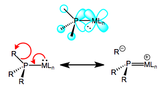
Backbonding in phosphines, a sigma-bond-breaking affair.
The steric and electronic properties of phosphines vary enormously. Tolman devised some intriguing parameters that characterize the steric and electronic properties of this class of ligands. To address sterics, he developed the idea of cone angle—the apex angle of a cone formed by a point 2.28 Å from the phosphorus atom (an idealized M–P bond length), and the outermost edges of atoms in the R groups, when the R groups are folded back as much as possible. Wider cone angles, Tolman reasoned, indicate greater steric congestion around the phosphorus atom. To address electronics, Tolman used a not-so-old friend of ours—the CO stretching frequency (νCO) of mixed phosphine-carbonyl complexes. Specifically, he used Ni(CO)3L complexes, where L is a tertiary phosphine, as his standard. Can you anticipate Tolman’s logic? How should νCO change as the electron-donating ability of the phosphine ligands increases?
Tolman’s logic went as follows: more strongly electron-donating phosphines are associated with more electron-rich metals, which are better at CO backbonding (due fundamentally to higher orbital energies). Better CO backbonding corresponds to a lower νCO due to decreased C–O bond order. Thus, better donor ligands should be associated with lower νCO values (and vice versa for electron-withdrawing ligands). Was he correct? Exhibit A…
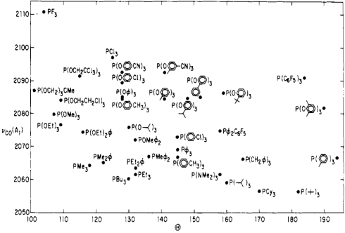
Tolman's map of the steric and electronic properties of phosphine ligands.
Notice the poor ligand trifluorophosphine stuck in the “very small, very withdrawing” corner, and its utter opposite, the gargantuan tri(tert-butyl)phosphine in the “extremely bulky, very donating” corner. Intriguing! One can learn a great deal just by studying this chart.
Dr. Michael Evans (Georgia Tech)
Bonding in Phosphine Complexes
Let us have a look at the MO diagram of the \(\ce{PH3}\) molecule and compare it with the \(\ce{NH3}\) molecule. As one would expect, the MOs are overall similar, but there is one important difference. While the LUMO in \(\ce{NH3}\) is the anti-bonding 3a1 orbital, the LUMOs in the \(\ce{PH3}\) molecule are the anti-bonding 2e orbitals. The relative energies of the 3a1 and 2e orbitals in the \(\ce{PH3}\) and \(\ce{NH3}\) molecules are swapped up. This can be attributed to the fact that the the P atom uses the 3s and the 3p orbitals as valence orbitals, while N uses the 2s and 2p orbitals. The 3s and the 3p orbitals are larger and overlap less effectively with the small 1s orbitals of the hydrogen. They also have a higher energy making the P-H bonds less polar than the N-H bonds. The energy of the \(\ce{PH3}\) HOMO is higher than that of the \(\ce{NH3}\) HOMO. Both the HOMO and the LUMO of \(\ce{PH3}\) are more diffuse and polarizable than the respective orbitals in \(\ce{NH3}\).
The higher energy of the HOMO in \(\ce{PH3}\) makes it a better donor than \(\ce{NH3}\). In addition, the \(\ce{PH3}\) has \(\pi\)-acceptor properties because the 2e LUMO are relatively low-lying anti-bonding 2e orbitals and have suitable shape for \(\pi\)-overlap with metal d-orbitals. \(\ce{NH3}\) does not have these \(\pi\)-acceptor properties because its LUMO is the 3a1 orbital, and not the 2e orbitals. The 2e orbitals in \(\ce{NH3}\) are energetically too high in order to allow for significant \(\pi\)-acceptor interactions.
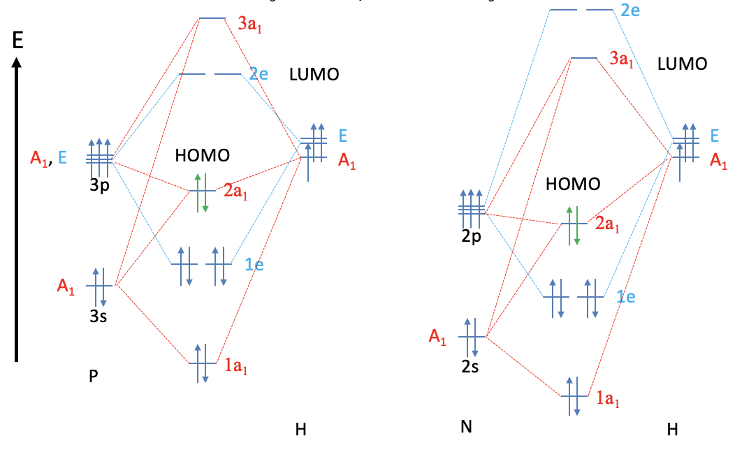
The \(\sigma\)-donor and \(\pi\)-acceptor properties of the phosphine ligand can be modified by substituting H by other groups. Generally, more electron donating groups increase the energy of the HOMO and the LUMO. This strengthens the \(\sigma\)-donor and reduces the \(\pi\)-acceptor properties. Vice versa, more electron withdrawing groups decrease the energy of the HOMO and the LUMO. As a consequence, the ligand becomes a weaker \(\sigma\)-donor and a stronger \(\pi\)-acceptor (Fig. \(\PageIndex{4}\)).
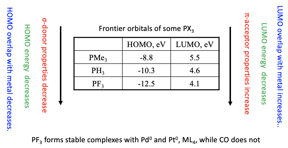
The table above shows the HOMO and LUMO energies of three phosphines. As expected the HOMO and LUMO energies decrease from \(\ce{PMe3}\) to \(\ce{PH3}\) to \(\ce{PF3}\) due to the increasingly electron-withdrawing nature of the substituent. As a consequence, the \(\sigma\)-donor properties weaken and the \(\pi\)-acceptor properties strengthen from to \(\ce{PMe3}\) to \(\ce{PH3}\) to \(\ce{PF3}\).
Not only the energies, but also the orbital overlap is important for the strength of the \(\pi\)-acceptor properties of the phosphine ligands. The more strongly electron-withdrawing the group is the more the anti-bonding e-type LUMO orbitals are located at the P atom. The more these orbitals are localized at P, the better they can overlap with the ligand. Vice versa the localization of the HOMO shifts toward the group as the group becomes more electron-withdrawing, thereby weakening the \(\sigma\)-donor properties.
Phosphine ligands with strongly electron withdrawing groups such as \(\ce{PF3}\) have \(\pi\)-acceptor properties strong enough to stabilize metals in low oxidation numbers, similar to \(\ce{CO}\). For example, the \(\ce{PF3}\) ligand forms stable complexes with Pd and Pt atoms in the oxidation number 0, while the respective Pd and Pt carbonyls are not known.
Dr. Kai Landskron (Lehigh University). If you like this textbook, please consider to make a donation to support the author's research at Lehigh University: Click Here to Donate.

