9.5: Molecular Geometry
- Page ID
- 3515
\( \newcommand{\vecs}[1]{\overset { \scriptstyle \rightharpoonup} {\mathbf{#1}} } \)
\( \newcommand{\vecd}[1]{\overset{-\!-\!\rightharpoonup}{\vphantom{a}\smash {#1}}} \)
\( \newcommand{\dsum}{\displaystyle\sum\limits} \)
\( \newcommand{\dint}{\displaystyle\int\limits} \)
\( \newcommand{\dlim}{\displaystyle\lim\limits} \)
\( \newcommand{\id}{\mathrm{id}}\) \( \newcommand{\Span}{\mathrm{span}}\)
( \newcommand{\kernel}{\mathrm{null}\,}\) \( \newcommand{\range}{\mathrm{range}\,}\)
\( \newcommand{\RealPart}{\mathrm{Re}}\) \( \newcommand{\ImaginaryPart}{\mathrm{Im}}\)
\( \newcommand{\Argument}{\mathrm{Arg}}\) \( \newcommand{\norm}[1]{\| #1 \|}\)
\( \newcommand{\inner}[2]{\langle #1, #2 \rangle}\)
\( \newcommand{\Span}{\mathrm{span}}\)
\( \newcommand{\id}{\mathrm{id}}\)
\( \newcommand{\Span}{\mathrm{span}}\)
\( \newcommand{\kernel}{\mathrm{null}\,}\)
\( \newcommand{\range}{\mathrm{range}\,}\)
\( \newcommand{\RealPart}{\mathrm{Re}}\)
\( \newcommand{\ImaginaryPart}{\mathrm{Im}}\)
\( \newcommand{\Argument}{\mathrm{Arg}}\)
\( \newcommand{\norm}[1]{\| #1 \|}\)
\( \newcommand{\inner}[2]{\langle #1, #2 \rangle}\)
\( \newcommand{\Span}{\mathrm{span}}\) \( \newcommand{\AA}{\unicode[.8,0]{x212B}}\)
\( \newcommand{\vectorA}[1]{\vec{#1}} % arrow\)
\( \newcommand{\vectorAt}[1]{\vec{\text{#1}}} % arrow\)
\( \newcommand{\vectorB}[1]{\overset { \scriptstyle \rightharpoonup} {\mathbf{#1}} } \)
\( \newcommand{\vectorC}[1]{\textbf{#1}} \)
\( \newcommand{\vectorD}[1]{\overrightarrow{#1}} \)
\( \newcommand{\vectorDt}[1]{\overrightarrow{\text{#1}}} \)
\( \newcommand{\vectE}[1]{\overset{-\!-\!\rightharpoonup}{\vphantom{a}\smash{\mathbf {#1}}}} \)
\( \newcommand{\vecs}[1]{\overset { \scriptstyle \rightharpoonup} {\mathbf{#1}} } \)
\(\newcommand{\longvect}{\overrightarrow}\)
\( \newcommand{\vecd}[1]{\overset{-\!-\!\rightharpoonup}{\vphantom{a}\smash {#1}}} \)
\(\newcommand{\avec}{\mathbf a}\) \(\newcommand{\bvec}{\mathbf b}\) \(\newcommand{\cvec}{\mathbf c}\) \(\newcommand{\dvec}{\mathbf d}\) \(\newcommand{\dtil}{\widetilde{\mathbf d}}\) \(\newcommand{\evec}{\mathbf e}\) \(\newcommand{\fvec}{\mathbf f}\) \(\newcommand{\nvec}{\mathbf n}\) \(\newcommand{\pvec}{\mathbf p}\) \(\newcommand{\qvec}{\mathbf q}\) \(\newcommand{\svec}{\mathbf s}\) \(\newcommand{\tvec}{\mathbf t}\) \(\newcommand{\uvec}{\mathbf u}\) \(\newcommand{\vvec}{\mathbf v}\) \(\newcommand{\wvec}{\mathbf w}\) \(\newcommand{\xvec}{\mathbf x}\) \(\newcommand{\yvec}{\mathbf y}\) \(\newcommand{\zvec}{\mathbf z}\) \(\newcommand{\rvec}{\mathbf r}\) \(\newcommand{\mvec}{\mathbf m}\) \(\newcommand{\zerovec}{\mathbf 0}\) \(\newcommand{\onevec}{\mathbf 1}\) \(\newcommand{\real}{\mathbb R}\) \(\newcommand{\twovec}[2]{\left[\begin{array}{r}#1 \\ #2 \end{array}\right]}\) \(\newcommand{\ctwovec}[2]{\left[\begin{array}{c}#1 \\ #2 \end{array}\right]}\) \(\newcommand{\threevec}[3]{\left[\begin{array}{r}#1 \\ #2 \\ #3 \end{array}\right]}\) \(\newcommand{\cthreevec}[3]{\left[\begin{array}{c}#1 \\ #2 \\ #3 \end{array}\right]}\) \(\newcommand{\fourvec}[4]{\left[\begin{array}{r}#1 \\ #2 \\ #3 \\ #4 \end{array}\right]}\) \(\newcommand{\cfourvec}[4]{\left[\begin{array}{c}#1 \\ #2 \\ #3 \\ #4 \end{array}\right]}\) \(\newcommand{\fivevec}[5]{\left[\begin{array}{r}#1 \\ #2 \\ #3 \\ #4 \\ #5 \\ \end{array}\right]}\) \(\newcommand{\cfivevec}[5]{\left[\begin{array}{c}#1 \\ #2 \\ #3 \\ #4 \\ #5 \\ \end{array}\right]}\) \(\newcommand{\mattwo}[4]{\left[\begin{array}{rr}#1 \amp #2 \\ #3 \amp #4 \\ \end{array}\right]}\) \(\newcommand{\laspan}[1]{\text{Span}\{#1\}}\) \(\newcommand{\bcal}{\cal B}\) \(\newcommand{\ccal}{\cal C}\) \(\newcommand{\scal}{\cal S}\) \(\newcommand{\wcal}{\cal W}\) \(\newcommand{\ecal}{\cal E}\) \(\newcommand{\coords}[2]{\left\{#1\right\}_{#2}}\) \(\newcommand{\gray}[1]{\color{gray}{#1}}\) \(\newcommand{\lgray}[1]{\color{lightgray}{#1}}\) \(\newcommand{\rank}{\operatorname{rank}}\) \(\newcommand{\row}{\text{Row}}\) \(\newcommand{\col}{\text{Col}}\) \(\renewcommand{\row}{\text{Row}}\) \(\newcommand{\nul}{\text{Nul}}\) \(\newcommand{\var}{\text{Var}}\) \(\newcommand{\corr}{\text{corr}}\) \(\newcommand{\len}[1]{\left|#1\right|}\) \(\newcommand{\bbar}{\overline{\bvec}}\) \(\newcommand{\bhat}{\widehat{\bvec}}\) \(\newcommand{\bperp}{\bvec^\perp}\) \(\newcommand{\xhat}{\widehat{\xvec}}\) \(\newcommand{\vhat}{\widehat{\vvec}}\) \(\newcommand{\uhat}{\widehat{\uvec}}\) \(\newcommand{\what}{\widehat{\wvec}}\) \(\newcommand{\Sighat}{\widehat{\Sigma}}\) \(\newcommand{\lt}{<}\) \(\newcommand{\gt}{>}\) \(\newcommand{\amp}{&}\) \(\definecolor{fillinmathshade}{gray}{0.9}\)Make sure you thoroughly understand the following essential ideas:
- Describe the manner in which repulsion between electron-pairs affects the orientation of the regions that contain them.
- Define coordination geometry, and describe the particular geometry associated with electron-pair repulsion between two, three, four, five, or six identical bonding regions.
- Explain the distinction between coordination geometry and molecular geometry, and provide an illustration based on the structure of water or ammonia.
- Draw a diagram of a tetrahedral or octahedral molecule.
The Lewis electron-dot structures you have learned to draw have no geometrical significance other than depicting the order in which the various atoms are connected to one another. Nevertheless, a slight extension of the simple shared-electron pair concept is capable of rationalizing and predicting the geometry of the bonds around a given atom in a wide variety of situations.
Electron-pair repulsion
The valence shell electron pair repulsion (VSEPR) model that we describe here focuses on the bonding and nonbonding electron pairs present in the outermost (“valence”) shell of an atom that connects with two or more other atoms. Like all electrons, these occupy regions of space which we can visualize as electron clouds— regions of negative electric charge, also known as orbitals— whose precise character can be left to more detailed theories
.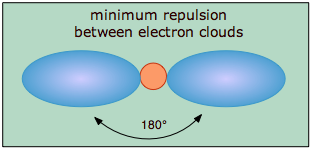
The covalent model of chemical bonding assumes that the electron pairs responsible for bonding are concentrated into the region of apace between the bonded atoms. The fundamental idea of VSEPR thoery is that these regions of negative electric charge will repel each other, causing them (and thus the chemical bonds that they form) to stay as far apart as possible. Thus the two electron clouds contained in a simple triatomic molecule AX2 will extend out in opposite directions; an angular separation of 180° places the two bonding orbitals as far away from each other they can get. We therefore expect the two chemical bonds to extend in opposite directions, producing a linear molecule.
If the central atom also contains one or more pairs of nonbonding electrons, these additional regions of negative charge will behave very much like those associated with the bonded atoms. The orbitals containing the various bonding and nonbonding pairs in the valence shell will extend out from the central atom in directions that minimize their mutual repulsions. If the central atom possesses partially occupied d-orbitals, it may be able to accommodate five or six electron pairs, forming what is sometimes called an “expanded octet”.
Digonal and trigonal coordination
Linear molecules
As we stated above, a simple triatomic molecule of the type \(AX_2\) has its two bonding orbitals 180° apart, producing a molecule that we describe as having linear geometry. Examples of triatomic molecules for which VSEPR theory predicts a linear shape are BeCl2 (which, you will notice, doesn't possess enough electrons to conform to the octet rule) and CO2. If you write out the electron dot formula for carbon dioxide, you will see that the C-O bonds are double bonds. This makes no difference to VSEPR theory; the central carbon atom is still joined to two other atoms, and the electron clouds that connect the two oxygen atoms are 180° apart.


Trigonal molecules
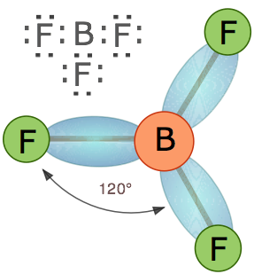
In an AX3 molecule such as BF3, there are three regions of electron density extending out from the central atom. The repulsion between these will be at a minimum when the angle between any two is (360° ÷ 3) = 120°. This requires that all four atoms be in the same plane; the resulting shape is called trigonal planar, or simply trigonal.
Tetrahedral coordination
Methane, CH4, contains a carbon atom bonded to four hydrogens. What bond angle would lead to the greatest possible separation between the electron clouds associated with these bonds? In analogy with the preceding two cases, where the bond angles were 360°/2=180° and 360°/3=120°, you might guess 360°/4=90°; if so, you would be wrong. The latter calculation would be correct if all the atoms were constrained to be in the same plane (we will see cases where this happens later), but here there is no such restriction. Consequently, the four equivalent bonds will point in four geometrically equivalent directions in three dimensions corresponding to the four corners of a tetrahedron centered on the carbon atom. The angle between any two bonds will be 109.5°. This is called tetrahedral coordination.
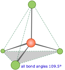
This is the most important coordination geometry in Chemistry: it is imperative that you be able to sketch at least a crude perspective view of a tetrahedral molecule.
It is interesting to note that the tetrahedral coordination of carbon in most of its organic compounds was worked out in the nineteenth century on purely geometrical grounds and chemical evidence, long before direct methods of determining molecular shapes were developed. For example, it was noted that there is only one dichloromethane, CH2Cl2.
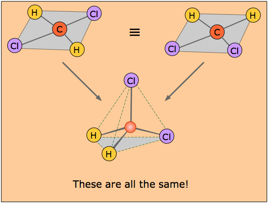
If the coordination around the carbon were square, then there would have to be two isomers of CH2Cl2, as shown in the pair of structures here. The distances between the two chlorine atoms would be different, giving rise to differences in physical properties would allow the two isomers to be distinguished and separated.
The existence of only one kind of CH2Cl2 molecule means that all four positions surrounding the carbon atom are geometrically equivalent, which requires a tetrahedral coordination geometry. If you study the tetrahedral figure closely, you may be able to convince yourself that it represents the connectivity shown on both of the "square" structures at the top. A three-dimensional ball-and-stick mechanical model would illustrate this very clearly.
Tetrahedrally-coordinated carbon chains
tetrahedra joined end-to-end.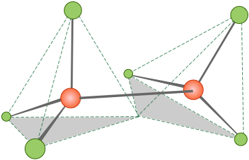
Similar alkane chains having the general formula H3C–(CH2)n–CH3 (or CnH2n+2) can be built up; a view of pentane, C5H12, is shown below.
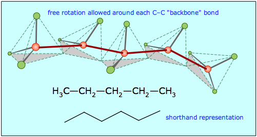
Notice that these "straight chain hydrocarbons" (as they are often known) have a carbon "backbone" structure that is not really straight, as is illustrated by the zig-zag figure that is frequently used to denote hydrocarbon structures.
Coordination geometry and molecular geometry
Coordination number refers to the number of electron pairs that surround a given atom; we often refer to this atom as the central atom even if this atom is not really located at the geometrical center of the molecule. If all of the electron pairs surrounding the central atom are shared with neighboring atoms, then the coordination geometry is the same as the molecular geometry. The application of VSEPR theory then reduces to the simple problem of naming (and visualizing) the geometric shapes associated with various numbers of points surrounding a central point (the central atom) at the greatest possible angles. Both classes of geometry are named after the shapes of the imaginary geometric figures (mostly regular solid polygons) that would be centered on the central atom and would have an electron pair at each vertex.
If one or more of the electron pairs surrounding the central atom is not shared with a neighboring atom (that is, if it is a lone pair), then the molecular geometry is simpler than the coordination geometry, and it can be worked out by inspecting a sketch of the coordination geometry figure.
Tetrahedral coordination with lone pairs
In the examples we have discussed so far, the shape of the molecule is defined by the coordination geometry; thus the carbon in methane is tetrahedrally coordinated, and there is a hydrogen at each corner of the tetrahedron, so the molecular shape is also tetrahedral.
The AXE Method
It is common practice to represent bonding patterns by "generic" formulas such as \(AX_4\), \(AX_2E_2\), etc., in which "X" stands for bonding pairs and "E" denotes lone pairs. This convention is known as the "AXE Method."
The bonding geometry will not be tetrahedral when the valence shell of the central atom contains nonbonding electrons, however. The reason is that the nonbonding electrons are also in orbitals that occupy space and repel the other orbitals. This means that in figuring the coordination number around the central atom, we must count both the bonded atoms and the nonbonding pairs.
The water molecule: \(AX_2E_2\)
In the water molecule, the central atom is O, and the Lewis electron dot formula predicts that there will be two pairs of nonbonding electrons. The oxygen atom will therefore be tetrahedrally coordinated, meaning that it sits at the center of the tetrahedron as shown below.
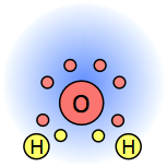
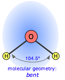
Two of the coordination positions are occupied by the shared electron-pairs that constitute the O–H bonds, and the other two by the non-bonding pairs. Thus although the oxygen atom is tetrahedrally coordinated, the bonding geometry (shape) of the H2O molecule is described asbent.
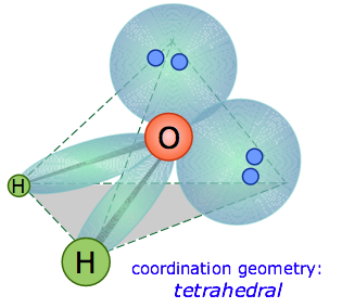
There is an important difference between bonding and non-bonding electron orbitals. Because a nonbonding orbital has no atomic nucleus at its far end to draw the electron cloud toward it, the charge in such an orbital will be concentrated closer to the central atom. As a consequence, nonbonding orbitals exert more repulsion on other orbitals than do bonding orbitals. Thus in H2O, the two nonbonding orbitals push the bonding orbitals closer together, making the H–O–H angle 104.5° instead of the tetrahedral angle of 109.5°.
Ammonia: \(AX_3E\)
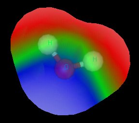
The electron-dot structure of NH3 places one pair of nonbonding electrons in the valence shell of the nitrogen atom. This means that there are three bonded atoms and one lone pair, for a coordination number of four around the nitrogen, the same as occurs in H2O. We can therefore predict that the three hydrogen atom will lie at the corners of a tetrahedron centered on the nitrogen atom. The lone pair orbital will point toward the fourth corner of the tetrahedron, but since that position will be vacant, the NH3molecule itself cannot be tetrahedral. Instead, it assumes a pyramidal shape. More precisely, the shape is that of a trigonal pyramid (i.e., a pyramid having a triangular base). The hydrogen atoms are all in the same plane, with the nitrogen above (or below, or to the side; molecules of course don’t know anything about “above” or “below”!) The fatter orbital containing the non-bonding electrons pushes the bonding orbitals together slightly, making the H–N–H bond angles about 107°.
Computer-generated image of NH3 molecule showing electrostatic potential (red=+, blue=–.)
Central atoms with five bonds
Compounds of the type AX5 are formed by some of the elements in Group 15 of the periodic table; PCl5 and AsF5 are examples.
In what directions can five electron pairs arrange themselves in space so as to minimize their mutual repulsions? In the cases of coordination numbers 2, 3, 4, and 6, we could imagine that the electron pairs distributed themselves as far apart as possible on the surface of a sphere; for the two higher numbers, the resulting shapes correspond to the regular polyhedron having the same number of sides. The problem with coordination number 5 is that there is no such thing as a regular polyhedron with five vertices.
Regular Polyhedra
In 1758, the great mathematician Euler proved that there are only five regular convex polyhedra, known as the platonic solids: tetrahedron (4 triangular faces), octahedron (6 triangular faces), icosahedron (20 triangular faces), cube (6 square faces), and dodecahedron (12 pentagonal faces). Chemical examples of all are known; the first icosahedral molecule, \(LaC_{60}\) (in which the La atom has 20 nearest C neighbors) was prepared in 1986.
Besides the five regular solids, there can be 15 semi-regular isogonal solids in which the faces have different shapes, but the vertex angles are all the same. These geometrical principles are quite important in modern structural chemistry.
The shape of PCl5 and similar molecules is a trigonal bipyramid. This consists simply of two triangular-base pyramids joined base-to-base. Three of the chlorine atoms are in the plane of the central phosphorus atom (equatorial positions), while the other two atoms are above and below this plane (axial positions). Equatorial and axial atoms have different geometrical relationships to their neighbors, and thus differ slightly in their chemical behavior.
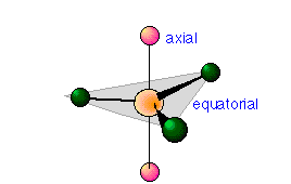
In 5-coordinated molecules containing lone pairs, these non-bonding orbitals (which you will recall are closer to the central atom and thus more likely to be repelled by other orbitals) will preferentially reside in the equatorial plane. This will place them at 90° angles with respect to no more than two axially-oriented bonding orbitals.
Using this reasoning, we can predict that an AX4E molecule (that is, a molecule in which the central atom A is coordinated to four other atoms “X” and to one nonbonding electron pair) such as SF4 will have a “see-saw” shape; substitution of more nonbonding pairs for bonded atoms reduces the triangular bipyramid coordination to even simpler molecular shapes, as shown below.

Octahedral coordination
Just as four electron pairs experience the minimum repulsion when they are directed toward the corners of a tetrahedron, six electron pairs will try to point toward the corners of an octahedron. An octahedron is not as complex a shape as its name might imply; it is simply two square-based pyramids joined base to base. You should be able to sketch this shape as well as that of the tetrahedron.
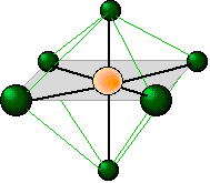
The shaded plane shown in this octahedrally-coordinated molecule is only one of three equivalent planes defined by a four-fold symmetry axis. All the ligands are geometrically equivalent; there are no separate axial and equatorial positions in an AX6 molecule.
At first, you might think that a coordination number of six is highly unusual; it certainly violates the octet rule, and there are only a few molecules (SF6 is one) where the central atom is hexavalent. It turns out, however, that this is one of the most commonly encountered coordination numbers in inorganic chemistry. There are two main reasons for this:
- Many transition metal ions form coordinate covalent bonds with lone-pair electron donor atoms such as N (in NH3) and O (in H2O). Since transition elements can have an outer configuration of d10s2, up to six electron pairs can be accommodated around the central atom. A coordination number of 6 is therefore quite common in transition metal hydrates, such as Fe(H2O)63+.
- Although the central atom of most molecules is bonded to fewer than six other atoms, there is often a sufficient number of lone pair electrons to bring the total number of electron pairs to six.
Octahedral coordination with lone pairs
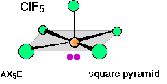
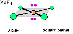
There are well known examples of 6-coordinate central atoms with 1, 2, and 3 lone pairs. Thus all three of the molecules whose shapes are depicted below possess octahedral coordination around the central atom. Note also that the orientation of the shaded planes shown in the two rightmost images are arbitrary; since all six vertices of an octahedron are identical, the planes could just as well be drawn in any of the three possible vertical orientations.
Summary of VSEPR theory
The VSEPR model is an extraordinarily powerful one, considering its great simplicity. Its application to predicting molecular structures can be summarized as follows:
- 1. Electron pairs surrounding a central atom repel each other; this repulsion will be minimized if the orbitals containing these electron pairs point as far away from each other as possible.
- 2. The coordination geometry around the central atom corresponds to the polyhedron whose number of vertices is equal to the number of surrounding electron pairs (coordination number). Except for the special case of 5, and the trivial cases of 2 and 3, the shape will be one of the regular polyhedra.
- 3. If some of the electron pairs are nonbonding, the shape of the molecule will be simpler than that of the coordination polyhedron.
- 4. Orbitals that contain nonbonding electrons are more concentrated near the central atom, and therefore offer more repulsion than bonding pairs to other orbitals.
While VSEPR theory is quite good at predicting the general shapes of most molecules, it cannot yield exact details. For example, it does not explain why the bond angle in H2O is 104.5°, but that in H2S is about 90°. This is not surprising, considering that the emphasis is on electronic repulsions, without regard to the detailed nature of the orbitals containing the electrons, and thus of the bonds themselves.
The Valence Shell Electron Repulsion theory was developed in the 1960s by Ronald Gillespie of McMaster University (Hamilton, Ontario, Canada) and Ronald Nyholm (University College, London). It is remarkable that what seems to be a logical extension of the 1916 Lewis shared-electron pair model of bonding took so long to be formulated; it was first presented in the authors' classic article Inorganic Stereochemistry published in the 1957 Chemical Society of London Quarterly Reviews (Vol 11, pg 339). Although it post-dates the more complete quantum mechanical models, it is easy to grasp and within a decade had become a staple of every first-year college chemistry course.


