7.9: The Analysis of Liquid Crystal Phases using Polarized Optical Microscopy
- Page ID
- 55915

\( \newcommand{\vecs}[1]{\overset { \scriptstyle \rightharpoonup} {\mathbf{#1}} } \)
\( \newcommand{\vecd}[1]{\overset{-\!-\!\rightharpoonup}{\vphantom{a}\smash {#1}}} \)
\( \newcommand{\id}{\mathrm{id}}\) \( \newcommand{\Span}{\mathrm{span}}\)
( \newcommand{\kernel}{\mathrm{null}\,}\) \( \newcommand{\range}{\mathrm{range}\,}\)
\( \newcommand{\RealPart}{\mathrm{Re}}\) \( \newcommand{\ImaginaryPart}{\mathrm{Im}}\)
\( \newcommand{\Argument}{\mathrm{Arg}}\) \( \newcommand{\norm}[1]{\| #1 \|}\)
\( \newcommand{\inner}[2]{\langle #1, #2 \rangle}\)
\( \newcommand{\Span}{\mathrm{span}}\)
\( \newcommand{\id}{\mathrm{id}}\)
\( \newcommand{\Span}{\mathrm{span}}\)
\( \newcommand{\kernel}{\mathrm{null}\,}\)
\( \newcommand{\range}{\mathrm{range}\,}\)
\( \newcommand{\RealPart}{\mathrm{Re}}\)
\( \newcommand{\ImaginaryPart}{\mathrm{Im}}\)
\( \newcommand{\Argument}{\mathrm{Arg}}\)
\( \newcommand{\norm}[1]{\| #1 \|}\)
\( \newcommand{\inner}[2]{\langle #1, #2 \rangle}\)
\( \newcommand{\Span}{\mathrm{span}}\) \( \newcommand{\AA}{\unicode[.8,0]{x212B}}\)
\( \newcommand{\vectorA}[1]{\vec{#1}} % arrow\)
\( \newcommand{\vectorAt}[1]{\vec{\text{#1}}} % arrow\)
\( \newcommand{\vectorB}[1]{\overset { \scriptstyle \rightharpoonup} {\mathbf{#1}} } \)
\( \newcommand{\vectorC}[1]{\textbf{#1}} \)
\( \newcommand{\vectorD}[1]{\overrightarrow{#1}} \)
\( \newcommand{\vectorDt}[1]{\overrightarrow{\text{#1}}} \)
\( \newcommand{\vectE}[1]{\overset{-\!-\!\rightharpoonup}{\vphantom{a}\smash{\mathbf {#1}}}} \)
\( \newcommand{\vecs}[1]{\overset { \scriptstyle \rightharpoonup} {\mathbf{#1}} } \)
\( \newcommand{\vecd}[1]{\overset{-\!-\!\rightharpoonup}{\vphantom{a}\smash {#1}}} \)
\(\newcommand{\avec}{\mathbf a}\) \(\newcommand{\bvec}{\mathbf b}\) \(\newcommand{\cvec}{\mathbf c}\) \(\newcommand{\dvec}{\mathbf d}\) \(\newcommand{\dtil}{\widetilde{\mathbf d}}\) \(\newcommand{\evec}{\mathbf e}\) \(\newcommand{\fvec}{\mathbf f}\) \(\newcommand{\nvec}{\mathbf n}\) \(\newcommand{\pvec}{\mathbf p}\) \(\newcommand{\qvec}{\mathbf q}\) \(\newcommand{\svec}{\mathbf s}\) \(\newcommand{\tvec}{\mathbf t}\) \(\newcommand{\uvec}{\mathbf u}\) \(\newcommand{\vvec}{\mathbf v}\) \(\newcommand{\wvec}{\mathbf w}\) \(\newcommand{\xvec}{\mathbf x}\) \(\newcommand{\yvec}{\mathbf y}\) \(\newcommand{\zvec}{\mathbf z}\) \(\newcommand{\rvec}{\mathbf r}\) \(\newcommand{\mvec}{\mathbf m}\) \(\newcommand{\zerovec}{\mathbf 0}\) \(\newcommand{\onevec}{\mathbf 1}\) \(\newcommand{\real}{\mathbb R}\) \(\newcommand{\twovec}[2]{\left[\begin{array}{r}#1 \\ #2 \end{array}\right]}\) \(\newcommand{\ctwovec}[2]{\left[\begin{array}{c}#1 \\ #2 \end{array}\right]}\) \(\newcommand{\threevec}[3]{\left[\begin{array}{r}#1 \\ #2 \\ #3 \end{array}\right]}\) \(\newcommand{\cthreevec}[3]{\left[\begin{array}{c}#1 \\ #2 \\ #3 \end{array}\right]}\) \(\newcommand{\fourvec}[4]{\left[\begin{array}{r}#1 \\ #2 \\ #3 \\ #4 \end{array}\right]}\) \(\newcommand{\cfourvec}[4]{\left[\begin{array}{c}#1 \\ #2 \\ #3 \\ #4 \end{array}\right]}\) \(\newcommand{\fivevec}[5]{\left[\begin{array}{r}#1 \\ #2 \\ #3 \\ #4 \\ #5 \\ \end{array}\right]}\) \(\newcommand{\cfivevec}[5]{\left[\begin{array}{c}#1 \\ #2 \\ #3 \\ #4 \\ #5 \\ \end{array}\right]}\) \(\newcommand{\mattwo}[4]{\left[\begin{array}{rr}#1 \amp #2 \\ #3 \amp #4 \\ \end{array}\right]}\) \(\newcommand{\laspan}[1]{\text{Span}\{#1\}}\) \(\newcommand{\bcal}{\cal B}\) \(\newcommand{\ccal}{\cal C}\) \(\newcommand{\scal}{\cal S}\) \(\newcommand{\wcal}{\cal W}\) \(\newcommand{\ecal}{\cal E}\) \(\newcommand{\coords}[2]{\left\{#1\right\}_{#2}}\) \(\newcommand{\gray}[1]{\color{gray}{#1}}\) \(\newcommand{\lgray}[1]{\color{lightgray}{#1}}\) \(\newcommand{\rank}{\operatorname{rank}}\) \(\newcommand{\row}{\text{Row}}\) \(\newcommand{\col}{\text{Col}}\) \(\renewcommand{\row}{\text{Row}}\) \(\newcommand{\nul}{\text{Nul}}\) \(\newcommand{\var}{\text{Var}}\) \(\newcommand{\corr}{\text{corr}}\) \(\newcommand{\len}[1]{\left|#1\right|}\) \(\newcommand{\bbar}{\overline{\bvec}}\) \(\newcommand{\bhat}{\widehat{\bvec}}\) \(\newcommand{\bperp}{\bvec^\perp}\) \(\newcommand{\xhat}{\widehat{\xvec}}\) \(\newcommand{\vhat}{\widehat{\vvec}}\) \(\newcommand{\uhat}{\widehat{\uvec}}\) \(\newcommand{\what}{\widehat{\wvec}}\) \(\newcommand{\Sighat}{\widehat{\Sigma}}\) \(\newcommand{\lt}{<}\) \(\newcommand{\gt}{>}\) \(\newcommand{\amp}{&}\) \(\definecolor{fillinmathshade}{gray}{0.9}\)Liquid Crystal Phases
Liquid crystals are a state of matter that has the properties between solid crystal and common liquid. There are basically three different types of liquid crystal phases:
- Thermotropic liquid crystal phases are dependent on temperature.
- Lyotropic liquid crystal phases are dependent on temperature and the concentration of LCs in the solvent.
- Metallotropic LCs are composed of organic and inorganic molecules, and the phase transition not only depend on temperature and concentration, but also depend on the ratio between organic and inorganic molecules.
Thermotropic LCs are the most widely used one, which can be divided into five categories:
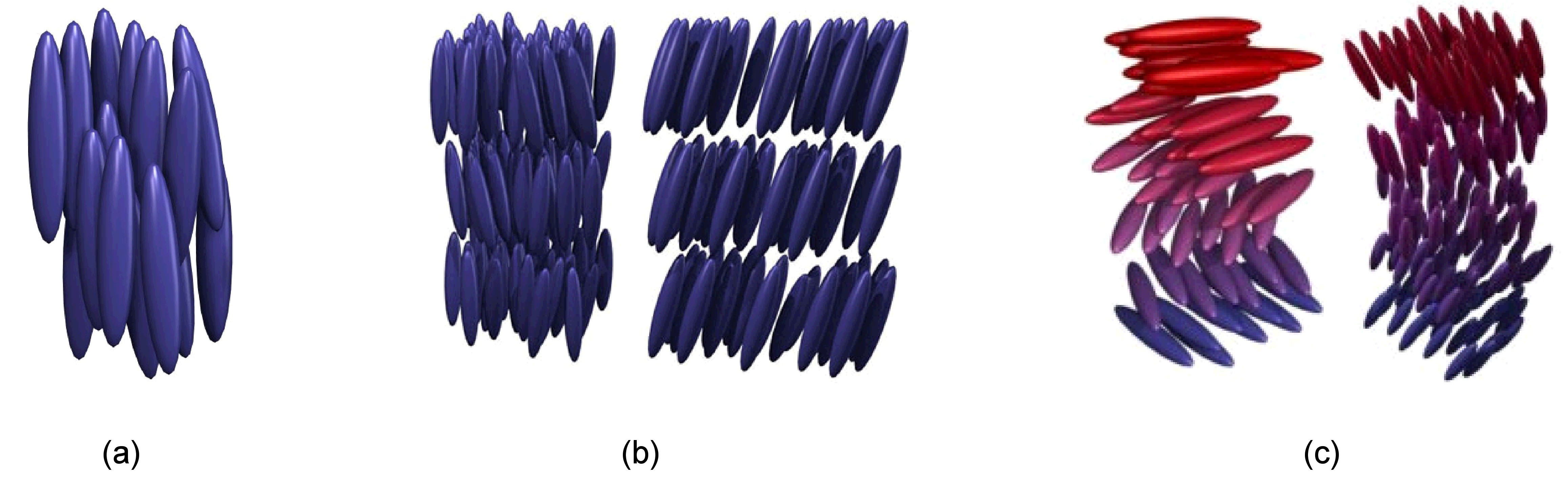
- Nematic phase in which rod-shaped molecules have no positional order, but they self-align to have long-range directional order with their long axes roughly parallel (Figure \(\PageIndex{1}\)a).
- Smactic phase where the molecules are positionally ordered along one direction in well-defined layers oriented either along the layer normal (smectic A) or tilted away from the layer normal (smectic C), see Figure \(\PageIndex{1}\)b.
- Chiral phase which exhibits a twisting of the molecules perpendicular to the director, with the molecular axis parallel to the director Figure \(\PageIndex{1}\) c.
- Blue phase having a regular three-dimensional cubic structure of defects with lattice periods of several hundred nanometers, and thus they exhibit selective Bragg reflections in the wavelength range of light Figure \(\PageIndex{2}\).
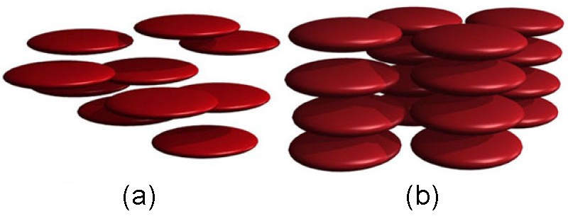
- Discotic phase in which disk-shaped LC molecules can orient themselves in a layer-like fashion Figure \(\PageIndex{3}\).

Thermotropic LCs are very sensitive to temperature. If the temperature is too high, thermal motion will destroy the ordering of LCs, and push it into a liquid phase. If the temperature is too low, thermal motion is hard to perform, so the material will become crystal phase.
The existence of liquid crystal phase can be detected by using polarized optical microscopy, since liquid crystal phase exhibits its unique texture under microscopy. The contrasting areas in the texture correspond to domains where LCs are oriented towards different directions.
Polarized Optical Microscopy
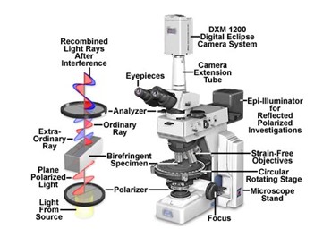
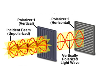
Polarized optical microscopy is typically used to detect the existence of liquid crystal phases in a solution.The principle of this is corresponding to the polarization of light. A polarizer is a filter that only permits the light oriented in a specific direction with its polarizing direction to pass through. There are two polarizers in a polarizing optical microscope (POM) (Figure \(\PageIndex{4}\)) and they are designed to be oriented at right angle to each other, which is termed as cross polar. The fundamental of cross polar is illustrated in Figure \(\PageIndex{5}\), the polarizing direction of the first polarizer is oriented vertically to the incident beam, so only the waves with vertical direction can pass through it. The passed wave is subsequently blocked by the second polarizer, since this polarizer is oriented horizontally to the incident wave.
Theory of Birefringence
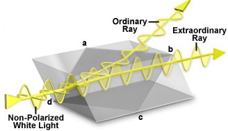
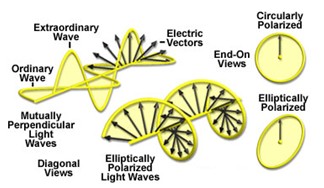
Birefringent or doubly-refracting sample has a unique property that it can produce two individual wave components while one wave passes through it, those two components are termed as ordinary and extraordinary waves. Figure \(\PageIndex{6}\) is an illustration of a typical construction of Nicol polarizing prism, as we can see, the non-plarized white light are splitted into two ray as it passes through the prism. The one travels out of the prism is called ordinary ray, and the other one is called extraordinary ray. So if we have a birefringent specimen located between the polarizer and analyzer, the initial light will be separated into two waves when it passes though the specimen. After exiting the specimen, the light components become out of phase, but are recombined with constructive and destructive interference when they pass through the analyzer. Now the combined wave will have elliptically or circularly polarized light wave, see Figure \(\PageIndex{7}\), image contrast arises from the interaction of plane-polarized light with a birefringent specimen so some amount of wave will pass through the analyzer and give a bright domain on the specimen.
Liquid Crystal Display
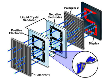
The most common application of LCs are in liquid crystals displays (LCD). Figure \(\PageIndex{8}\) is a simple demonstration of how LCD works in digit calculators. There are two crossed polarizers in this system, and liquid crystal (cholesteric spiral pattern) sandwich with positive and negative charging is located between these two polarizers. When the liquid crystal is charged, waves can pass through without changing orientations. When the liquid crystal is out of charge, waves will be rotated 90° as it passes through LCs so it can pass through the second polarizer. There are seven separately charged electrodes in the LCD, so the LCD can exhibit different numbers from 0 to 9 by adjusting the electrodes. For example, when the upper right and lower left electrodes are charged, we can get 2 on the display.
Microscope Images of Liquid Crystal Phase
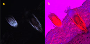
The first order retardation plate is frequently utilized to determine the optical sign of a birefringent specimen in polarized light microscopy. The optical sign includes positive and negative. If the ordinary wavefront is faster than the extraordinary wavefront (see Figure \(\PageIndex{9}\) a). When a first order retardation plate is added, the structure of the cell become all apparent compared with the one without retardation plate, Figure \(\PageIndex{9}\) b).
Images of Liquid Crystal Phases
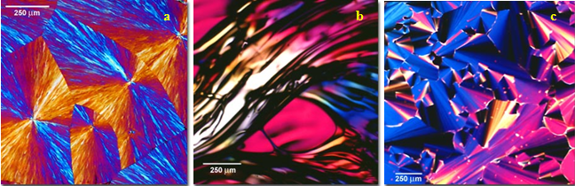
Figure \(\PageIndex{10}\) shows the images of liquid crystal phases from different specimens. First order retardation plates are utilized in all of these images. Apparent contrasts are detected here in the image which corresponds to the existence of liquid crystal phase within the specimen.
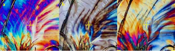
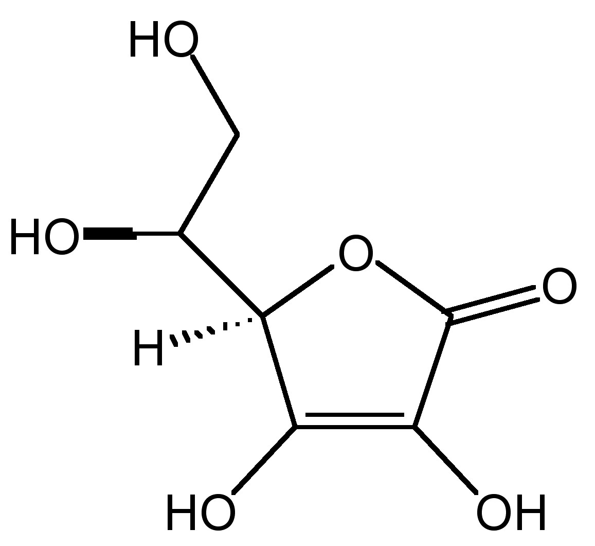
The Effect of Rotation of the Polarizer
The effect of the angle between horizontal direction and polarizer transmission axis on the appearance of liquid crystal phase may be analyzed. In Figure \(\PageIndex{11}\) is show images of an ascorbic acid (Figure \(\PageIndex{12}\)) sample under cross polar mode. When the polarizer rotates from 0° to 90°, big variations on the shape of bright domains and domain colors appear due to the change of wave vibrating directions. By rotating the polarizer, we can have a comprehensive understanding of the overall texture.