
7.5: Neutron Diffraction
- Page ID
- 55910

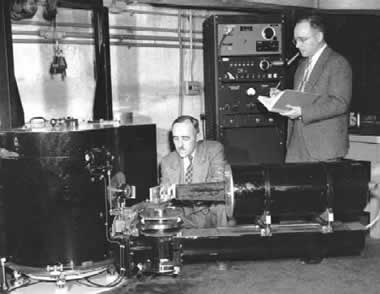
The first neutron diffraction experiment was in 1945 by Ernest O. Wollan (Figure \(\PageIndex{1}\)) using the Graphite Reactor at Oak Ridge. Along with Clifford Shull (Figure \(\PageIndex{1}\)) they outlined the principles of the technique. However, the concept that neutrons would diffract like X-rays was first proposed by Dana Mitchell and Philip Powers. They proposed that neutrons have a wave like structure, which is explained by the de Broglie equation, \ref{1}, where \(λ\) is the wavelength of the source usually measured in Å, \(h\) is Planck’s constant, \(v\) is the velocity of the neutron, and finally \(m\) represents the mass of the neutron.
\[ \lambda \ =\ h/mv \label{1} \]
The great majority of materials that are studied by diffraction methods are composed of crystals. X-rays where the first type of source tested with crystals in order to determine their structural characteristics. Crystals are said to be perfect structures although some of them show defects on their structure. Crystals are composed of atoms, ions or molecules, which are arranged, in a uniform repeating pattern. The basic concept to understand about crystals is that they are composed of an array of points, which are called lattice points, and the motif, which represents the body part of the crystal. Crystals are composed of a series of unit cells. A unit cell is the repeating portion of the crystal. Usually there are another eight unit cells surrounding each unit cell. Unit cells can be categorized as primitive, which have only one lattice point. This means that the unit cell will only have lattice points on the corners of the cell. This point is going to be shared with eight other unit cells. Whereas in a non primitive cell there will also be point in the corners of the cell but in addition there will be lattice points in the faces or the interior of the cell, which similarly will be shared by other cells. The only primitive cell known is the simple crystal system and for nonprimitive cells there are known face-centered cubic, base centered cubic and body centered cubic.
Crystals can be categorized depending on the arrangement of lattice points; this will generate different types of shapes. There are known seven crystal systems, which are cubic, tetragonal, orthorhombic, rhombohedral, hexagonal, monoclinic and triclinic. All of these have different angles and the axes are equally the same or different in others. Each of these type of systems have different bravais lattice.
Braggs Law
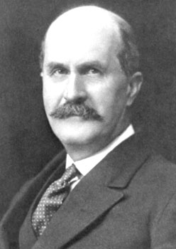
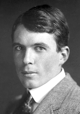
Braggs Law was first derived by physicist Sir W.H. Bragg (Figure \(\PageIndex{2}\)) and his son W. L Bragg (Figure \(\PageIndex{3}\)) in 1913.
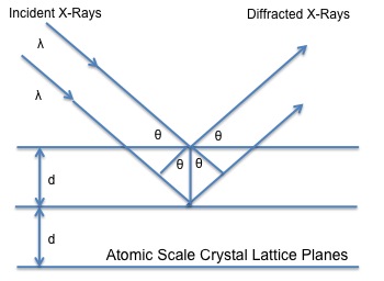
It has been used to determine the spacing of planes and angles formed between these planes and the incident beam that had been applied to the crystal examined. Intense scattered X-rays are produced when X-rays with a set wavelength are executed to a crystal. These scattered X-rays will interfere constructively due the equality in the differences between the travel path and the integral number of the wavelength. Since crystals have repeating units patterns, diffraction can be seen in terms of reflection from the planes of the crystals. The incident beam, the diffracted beam and normal plane to diffraction need to lie in the same geometric plane. The angle, which the incident beam forms when it hits the plane of the crystal, is called \(2θ\). Figure \(\PageIndex{4}\) shows a schematic representation of how the incident beam hits the plane of the crystal and is reflected at the same angle \(2θ\), which the incident beam hits. Bragg’s Law is mathematically expressed, \ref{2}:
\[ n\lambda = 2d \sin \theta \label{2} \]
where \(n\) is the integer order of reflection, \(λ\)= wavelength, and \(d\)= plane spacing.
Bragg’s Law is essential in determining the structure of an unknown crystal. Usually the wavelength is known and the angle of the incident beam can be measured. Having these two known values, the plane spacing of the layer of atoms or ions can be obtained. All reflections collected can be used to determine the structure of the unknown crystal material.
Bragg’s Law applies similarly to neutron diffraction. The same relationship is used the only difference being is that instead of using X-rays as the source, neutrons that are ejected and hit the crystal are being examined.
Neutron Diffraction
Neutrons have been studied for the determination of crystalline structures. The study of materials by neutron radiation has many advantages against the normally used such as X-rays and electrons. Neutrons are scattered by the nucleus of the atoms rather than X-rays, which are scattered by the electrons of the atoms. These generates several differences between them such as that scattering of X-rays highly depend on the atomic number of the atoms whereas neutrons depend on the properties of the nucleus. These lead to a greater and accurately identification of the unknown sample examined if neutron source is being used. The nucleus of every atom and even from isotopes of the same element is completely different. They all have different characteristics, which make neutron diffraction a great technique for identification of materials, which have similar elemental composition. In contrast, X-rays will not give an exact solution if similar characteristics are known between materials. Since the diffraction will be similar for adjacent atoms further analysis needs to be done in order to determine the structure of the unknown. Also, if the sample contains light elements such as hydrogen, it is almost impossible to determine the exact location of each of them just by X-ray diffraction or any other technique. Neutron diffraction can tell the number of light elements and the exact position of them present in the structure.
Neutron Inventors
Neutrons were first discovered by James Chadwick in 1932 Figure \(\PageIndex{5}\) when he showed that there were uncharged particles in the radiation he was using. These particles had a similar mass of the protons but did not have the same characteristics as them. Chadwick followed some of the predictions of Rutherford who first worked in this unknown field. Later, Elsasser designed the first neutron diffraction in 1936 and the ones responsible for the actual constructing were Halban and Preiswerk. This was first constructed for powders but later Mitchell and Powers developed and demonstrated the single crystal system. All experiments realized in early years were developed using radium and beryllium sources. The neutron flux from these was not sufficient for the characterization of materials. Then, years passed and neutron reactors had to be constructed in order to increase the flux of neutrons to be able to realize a complete characterization the material being examined.
Between mid and late 40s neutron sources began to appear in countries such as Canada, UK and some other of Europe. Later in 1951 Shull and Wollan presented a paper that discussed the scattering lengths of 60 elements and isotopes, which generated a broad opening of neutron diffraction for the structural information that can be obtained from neutron diffraction.

Neutron Sources
The first source of neutrons for early experiments was gathered from radium and beryllium sources. The problem with this, as already mentioned, was that the flux was not enough to perform huge experiments such as the determination of the structure of an unknown material. Nuclear reactors started to emerge in early 50s and these had a great impact in the scientific field. In the 1960s neutron reactors were constructed depending on the desired flux required for the production of neutron beams. In USA the first one constructed was the High Flux Beam Reactor (HFBR). Later, this was followed by one at Oak Ridge Laboratory (HFIR) (Figure \(\PageIndex{6}\)), which also was intended for isotope production and a couple of years later the ILL was built. This last one is the most powerful so far and it was built by collaboration between Germany and France. These nuclear reactors greatly increased the flux and so far there has not been constructed any other better reactor. It has been discussed that probably the best solution to look for greater flux is to look for other approaches for the production of neutrons such as accelerator driven sources. These could greatly increase the flux of neutrons and in addition other possible experiments could be executed. The key point in these devices is spallation, which increases the number of neutrons executed from a single proton and the energy released is minimal. Currently, there are several of these around the world but investigations continue searching for the best approach of the ejection of neutrons.

Neutron Detectors
Although neutrons are great particles for determining complete structures of materials they have some disadvantages. These particles experiment a reasonably weak scattering when looking especially to soft materials. This is a huge concern because there can be problems associated with the scattering of the particles which can lead to a misunderstanding in the analysis of the structure of the material.
Neutrons are particles that have the ability to penetrate through the surface of the material being examined. This is primarily due to the nuclear interaction produced from the particles and the nucleus from the material. This interaction is much greater that the one performed from the electrons, which it is only an electrostatic interaction. Also, it cannot be omitted the interaction that occurs between the electrons and the magnetic moment of the neutrons. All of these interactions discussed are of great advantage for the determination of the structure since neutrons interacts with every single nucleus in the material. The problem comes when the material is being analyzed because neutrons being uncharged materials make them difficult to detect them. For this reason, neutrons need to be reacted in order to generate charged particles, ions. Some of the reactions uusually used for the detection of neutrons are:
\[ n\ +\ ^{3}He \rightarrow \ ^{3}H\ +\ ^{1}H\ +\ 0.764 MeV \label{3} \]
\[ n\ +\ ^{10}B \rightarrow \ ^{7}Li\ +\ ^{4}He\ +\ \gamma \ +\ 2.3 MeV \label{4} \]
\[ n\ +\ ^{6}Li \rightarrow \ ^{4}He\ +\ ^{3}H\ +\ 4.79 MeV \label{5} \]
The first two reactions apply when the detection is performed in a gas environment whereas the third one is carried out in a solid. In each of these reaction there is a large cross section, which makes them ideal for neutron capture. The neutron detection hugely depends on the velocity of the particles. As velocity increases, shorter wavelengths are produced and the less efficient the detection becomes. The particles that are executed to the material need to be as close as possible in order to have an accurate signal from the detector. These signal needs to be quickly transduced and the detector should be ready to take the next measurement.
In gas detectors the cylinder is filled up with either 3He or BF3. The electrons produced by the secondary ionization interact with the positively charged anode wire. One disadvantage of this detector is that it cannot be attained a desired thickness since it is very difficult to have a fixed thickness with a gas. In contrast, in scintillator detectors since detection is developed in a solid, any thickness can be obtained. The thinner the thickness of the solid the more efficient the results obtained become. Usually the absorber is 6Li and the substrate, which detects the products, is phosphor, which exhibits luminescence. This emission of light produced from the phosphor results from the excitation of this when the ions pass thorough the scintillator. Then the signal produced is collected and transduced to an electrical signal in order to tell that a neutron has been detected.
Neutron Scattering
One of the greatest features of neutron scattering is that neutrons are scattered by every single atomic nucleus in the material whereas in X-ray studies, these are scattered by the electron density. In addition, neutron can be scattered by the magnetic moment of the atoms. The intensity of the scattered neutrons will be due to the wavelength at which it is executed from the source. Figure \(\PageIndex{7}\) shows how a neutron is scattered by the target when the incident beam hits it.
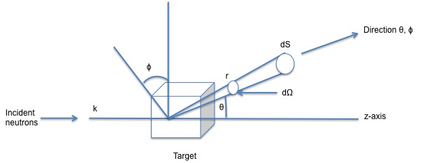
The incident beam encounters the target and the scattered wave produced from the collision is detected by a detector at a defined position given by the angles θ, ϕ which are joined by the dΩ. In this scenario there is assumed that there is no transferred energy between the nucleus of the atoms and the neutron ejected, leads to an elastic scattering.
When there is an interest in calculating the diffracted intensities the cross sectional area needs to be separated into scattering and absorption respectively. In relation to the energies of these there is moderately large range for constant scattering cross section. Also, there is a wide range cross sections close to the nuclear resonance. When the energies applied are less than the resonance the scattering length and scattering cross section are moved to the negative side depending on the structure being examined. This means that there is a shift on the scattering, therefore the scattering will not be in a 180° phase. When the energies are higher that resonance it means that the cross section will be asymptotic to the nucleus area. This will be expected for spherical structures. There is also resonance scattering when there are different isotopes because each produce different nuclear energy levels.
Coherent and Incoherent Scattering
Usually in every material, atoms will be arranged differently. Therefore, neutrons when scattered will be either coherently or incoherently. It is convenient to determine the differential scattering cross section, which is given by \ref{6}, where b represents the mean scattering length of the atoms, k is the scattering vector, r nis the position of the vector of the analyzed atom and lastly N is the total number of atoms in the structure.This equation can be separated in two parts, which one corresponds to the coherent scattering and the incoherent scattering as labeled below. Usually the particles scattered will be coherent which facilitates the solution of the cross section but when there is a difference in the mean scattering length, there will be a complete arrangement of the formula and these new changes (incoherent scattering) should be considered. Incoherent scattering is usually due to the isotopes and nuclear spins of the atoms in the structure.
\[ d\sigma /d\Omega \ =\ |b|^{2}\ |\Sigma e^{(ik.r_{n})}\ |^{2}\ +\ N|b-b^2| \label{6} \]
Coherent Exp: \[ |b|^{2}\ |\Sigma e^{(ik.r_{n})}\ |^{2} \nonumber \]
Incoherent Exp: \[ N\ |b-b|^{2} \nonumber \]
The ability to distinguish atoms with similar atomic number or isotopes is proportional to the square of their corresponding scattering lengths. There are already known several coherent scattering lengths of some atoms which are very similar to each other. Therefore, it makes even easier to identify by neutrons the structure of a sample. Also neutrons can find ions of light elements because they can locate very low atomic number elements such as hydrogen. Due to the negative scattering that hydrogen develops it increases the contrast leading to a better identification of it, although it has a very large incoherent scattering which causes electrons to be removed from the incident beam applied.
Magnetic Scattering
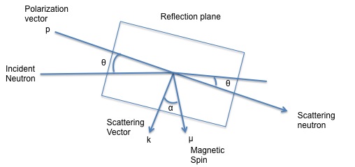
As previously mentioned one of the greatest features about neutron diffraction is that neutrons because of their magnetic moment can interact with either the orbital or the spin magnetic moment of the material examined. Not all every single element in the periodic table can exhibit a magnetic moment. The only elements that show a magnetic moment are those, which have unpaired electrons spins. When neutrons hit the solid this produces a scattering from the magnetic moment vector as well as the scattering vector from the neutron itself. Below Figure \(\PageIndex{8}\) shows the different vectors produced when the incident beam hits the solid.
When looking at magnetic scattering it needs to be considered the coherent magnetic diffraction peaks where the magnetic contribution to the differential cross section is p2q2 for an unpolarized incident beam. Therefore the magnetic structure amplitude will be given by \ref{9}, where qn is the magnetic interaction vector, pn is the magnetic scattering length and the rest of the terms are used to know the position of the atoms in the unit cell. When this term \(F_{mag}\) is squared, the result is the intensity of magnetic contribution from the peak analyzed. This equation only applies to those elements which have atoms that develop a magnetic moment.
\[ F_{\text{mag}}\ =\ \Sigma p_{n}q_{n} e^{2\pi i(hx_{n}\ +\ ky_{n}\ +\ Iz_{n})} \label{9} \]
Magnetic diffraction becomes very important due to its d-spacing dependence. Due to the greater effect produced from the electrons in magnetic scattering the forward scattering has a greater strength than the backward scattering. There can also be developed similar as in X-ray, interference between the atoms which makes structure factor also be considered. These interference effects could be produced by the wide range in difference between the electron distribution and the wavelength of the thermal neutrons. This factor quickly decreases as compared to X-rays because the beam only interacts with the outer electrons of the atoms.
Sample Preparation and Environment
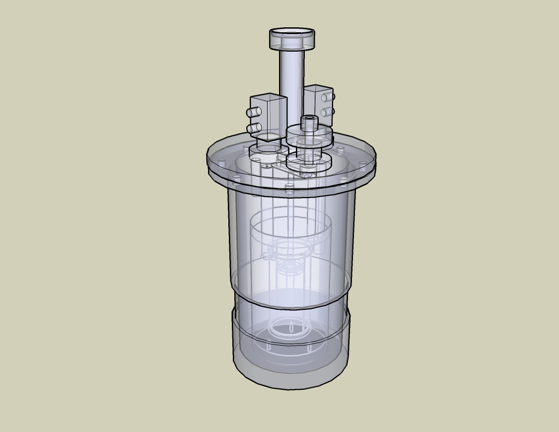
In neutron diffraction there is not a unique protocol of factors that should be considered such as temperature, electric field and pressure to name a few. Depending on the type of material and data that has been looked the parameters are assigned. There can be reached very high temperatures such as 1800K or it can go as low as 4K. Usually to get to these extreme temperatures a special furnace capable of reaching these temperatures needs to be used. For example, one of the most common used is the He refrigerator when working with very low temperatures. For high temperatures, there are used furnaces with a heating element cylinder such as vanadium (V), niobium (Nb), tantalum (Ta) or tungsten (W) that is attached to copper bars which hold the sample. Figure \(\PageIndex{9}\) shows the design for the vacuum furnaces used for the analysis. The metal that works best at the desired temperature range will be the one chosen as the heating element. The metal that is commonly used is vanadium because it prevents the contribution of other factors such as coherent scattering. Although with this metal this type of scattering is almost completely reduced. Other important factor about this furnaces is that the material been examined should not decompose under vacuum conditions. The crystal needs to be as stable as possible when it is being analyzed. When samples are not able to persist at a vacuum environment, they are heated in the presence of several gases such as nitrogen or argon.
Usually in order to prepare the samples that are being examined in neutron diffraction it is needed large crystals rather small ones as the one needed for X-ray studies. This one of the main disadvantages of this instrument. Most experiments are carried out using a four-circle diffractometer. The main reason being is because several experiment are carried out using very low temperatures and in order to achieve a good spectra it is needed the He refrigerator. First, the crystal being analyzed is mounted on a quartz slide, which needs to be a couple millimeters in size. Then, it is inserted into the sample holder, which is chosen depending on the temperatures wanted to be reached. In addition, neutrons can also analyze powder samples and in order to prepare the sample for these they need to be completely rendered into very fine powders and then inserted into the quartz slide similarly to the crystal structures. The main concern with this method is that when samples are grounded into powders the structure of the sample being examined can be altered.
Summary
Neutron diffraction is a great technique used for complete characterization of molecules involving light elements and also very useful for the ones that have different isotopes in the structure. Due to the fact that neutrons interact with the nucleus of the atoms rather than with the outer electrons of the atoms such as X-rays, it leads to a more reliable data. In addition, due to the magnetic properties of the neutrons there can be characterized magnetic compounds due to the magnetic moment that neutrons develop. There are several disadvantages as well, one of the most critical is that there needs to be a good amount of sample in order to be analyzed by this technique. Also, great amounts of energy are needed to produce large amounts of neutrons. There are several powerful neutron sources that have been developed in order to conduct studies of largest molecules and a smaller quantity of sample. However, there is still the need of devices which can produce a great amount of flux to analyze more sophisticated samples. Neutron diffraction has been widely studied due to the fact that it works together with X-rays studies for the characterization of crystalline samples. The properties and advantages of this technique can greatly increased if some of the disadvantages are solved. For example, the study of molecules which exhibit some type of molecular force can be characterized. This will be because neutrons can precisely locate hydrogen atoms in a sample. Neutrons have gives a better answer to the chemical interactions that are present in every single molecule, whereas X-rays help to give an idea of the macromolecular structure of the samples being examined.