
Capillary Electrophoresis
- Page ID
- 294
\( \newcommand{\vecs}[1]{\overset { \scriptstyle \rightharpoonup} {\mathbf{#1}} } \)
\( \newcommand{\vecd}[1]{\overset{-\!-\!\rightharpoonup}{\vphantom{a}\smash {#1}}} \)
\( \newcommand{\dsum}{\displaystyle\sum\limits} \)
\( \newcommand{\dint}{\displaystyle\int\limits} \)
\( \newcommand{\dlim}{\displaystyle\lim\limits} \)
\( \newcommand{\id}{\mathrm{id}}\) \( \newcommand{\Span}{\mathrm{span}}\)
( \newcommand{\kernel}{\mathrm{null}\,}\) \( \newcommand{\range}{\mathrm{range}\,}\)
\( \newcommand{\RealPart}{\mathrm{Re}}\) \( \newcommand{\ImaginaryPart}{\mathrm{Im}}\)
\( \newcommand{\Argument}{\mathrm{Arg}}\) \( \newcommand{\norm}[1]{\| #1 \|}\)
\( \newcommand{\inner}[2]{\langle #1, #2 \rangle}\)
\( \newcommand{\Span}{\mathrm{span}}\)
\( \newcommand{\id}{\mathrm{id}}\)
\( \newcommand{\Span}{\mathrm{span}}\)
\( \newcommand{\kernel}{\mathrm{null}\,}\)
\( \newcommand{\range}{\mathrm{range}\,}\)
\( \newcommand{\RealPart}{\mathrm{Re}}\)
\( \newcommand{\ImaginaryPart}{\mathrm{Im}}\)
\( \newcommand{\Argument}{\mathrm{Arg}}\)
\( \newcommand{\norm}[1]{\| #1 \|}\)
\( \newcommand{\inner}[2]{\langle #1, #2 \rangle}\)
\( \newcommand{\Span}{\mathrm{span}}\) \( \newcommand{\AA}{\unicode[.8,0]{x212B}}\)
\( \newcommand{\vectorA}[1]{\vec{#1}} % arrow\)
\( \newcommand{\vectorAt}[1]{\vec{\text{#1}}} % arrow\)
\( \newcommand{\vectorB}[1]{\overset { \scriptstyle \rightharpoonup} {\mathbf{#1}} } \)
\( \newcommand{\vectorC}[1]{\textbf{#1}} \)
\( \newcommand{\vectorD}[1]{\overrightarrow{#1}} \)
\( \newcommand{\vectorDt}[1]{\overrightarrow{\text{#1}}} \)
\( \newcommand{\vectE}[1]{\overset{-\!-\!\rightharpoonup}{\vphantom{a}\smash{\mathbf {#1}}}} \)
\( \newcommand{\vecs}[1]{\overset { \scriptstyle \rightharpoonup} {\mathbf{#1}} } \)
\(\newcommand{\longvect}{\overrightarrow}\)
\( \newcommand{\vecd}[1]{\overset{-\!-\!\rightharpoonup}{\vphantom{a}\smash {#1}}} \)
\(\newcommand{\avec}{\mathbf a}\) \(\newcommand{\bvec}{\mathbf b}\) \(\newcommand{\cvec}{\mathbf c}\) \(\newcommand{\dvec}{\mathbf d}\) \(\newcommand{\dtil}{\widetilde{\mathbf d}}\) \(\newcommand{\evec}{\mathbf e}\) \(\newcommand{\fvec}{\mathbf f}\) \(\newcommand{\nvec}{\mathbf n}\) \(\newcommand{\pvec}{\mathbf p}\) \(\newcommand{\qvec}{\mathbf q}\) \(\newcommand{\svec}{\mathbf s}\) \(\newcommand{\tvec}{\mathbf t}\) \(\newcommand{\uvec}{\mathbf u}\) \(\newcommand{\vvec}{\mathbf v}\) \(\newcommand{\wvec}{\mathbf w}\) \(\newcommand{\xvec}{\mathbf x}\) \(\newcommand{\yvec}{\mathbf y}\) \(\newcommand{\zvec}{\mathbf z}\) \(\newcommand{\rvec}{\mathbf r}\) \(\newcommand{\mvec}{\mathbf m}\) \(\newcommand{\zerovec}{\mathbf 0}\) \(\newcommand{\onevec}{\mathbf 1}\) \(\newcommand{\real}{\mathbb R}\) \(\newcommand{\twovec}[2]{\left[\begin{array}{r}#1 \\ #2 \end{array}\right]}\) \(\newcommand{\ctwovec}[2]{\left[\begin{array}{c}#1 \\ #2 \end{array}\right]}\) \(\newcommand{\threevec}[3]{\left[\begin{array}{r}#1 \\ #2 \\ #3 \end{array}\right]}\) \(\newcommand{\cthreevec}[3]{\left[\begin{array}{c}#1 \\ #2 \\ #3 \end{array}\right]}\) \(\newcommand{\fourvec}[4]{\left[\begin{array}{r}#1 \\ #2 \\ #3 \\ #4 \end{array}\right]}\) \(\newcommand{\cfourvec}[4]{\left[\begin{array}{c}#1 \\ #2 \\ #3 \\ #4 \end{array}\right]}\) \(\newcommand{\fivevec}[5]{\left[\begin{array}{r}#1 \\ #2 \\ #3 \\ #4 \\ #5 \\ \end{array}\right]}\) \(\newcommand{\cfivevec}[5]{\left[\begin{array}{c}#1 \\ #2 \\ #3 \\ #4 \\ #5 \\ \end{array}\right]}\) \(\newcommand{\mattwo}[4]{\left[\begin{array}{rr}#1 \amp #2 \\ #3 \amp #4 \\ \end{array}\right]}\) \(\newcommand{\laspan}[1]{\text{Span}\{#1\}}\) \(\newcommand{\bcal}{\cal B}\) \(\newcommand{\ccal}{\cal C}\) \(\newcommand{\scal}{\cal S}\) \(\newcommand{\wcal}{\cal W}\) \(\newcommand{\ecal}{\cal E}\) \(\newcommand{\coords}[2]{\left\{#1\right\}_{#2}}\) \(\newcommand{\gray}[1]{\color{gray}{#1}}\) \(\newcommand{\lgray}[1]{\color{lightgray}{#1}}\) \(\newcommand{\rank}{\operatorname{rank}}\) \(\newcommand{\row}{\text{Row}}\) \(\newcommand{\col}{\text{Col}}\) \(\renewcommand{\row}{\text{Row}}\) \(\newcommand{\nul}{\text{Nul}}\) \(\newcommand{\var}{\text{Var}}\) \(\newcommand{\corr}{\text{corr}}\) \(\newcommand{\len}[1]{\left|#1\right|}\) \(\newcommand{\bbar}{\overline{\bvec}}\) \(\newcommand{\bhat}{\widehat{\bvec}}\) \(\newcommand{\bperp}{\bvec^\perp}\) \(\newcommand{\xhat}{\widehat{\xvec}}\) \(\newcommand{\vhat}{\widehat{\vvec}}\) \(\newcommand{\uhat}{\widehat{\uvec}}\) \(\newcommand{\what}{\widehat{\wvec}}\) \(\newcommand{\Sighat}{\widehat{\Sigma}}\) \(\newcommand{\lt}{<}\) \(\newcommand{\gt}{>}\) \(\newcommand{\amp}{&}\) \(\definecolor{fillinmathshade}{gray}{0.9}\)Capillary electrophoresis is an analytical technique that separates ions based on their electrophoretic mobility with the use of an applied voltage. The electrophoretic mobility is dependent upon the charge of the molecule, the viscosity, and the atom's radius. The rate at which the particle moves is directly proportional to the applied electric field--the greater the field strength, the faster the mobility. Neutral species are not affected, only ions move with the electric field. If two ions are the same size, the one with greater charge will move the fastest. For ions of the same charge, the smaller particle has less friction and overall faster migration rate. Capillary electrophoresis is used most predominately because it gives faster results and provides high resolution separation. It is a useful technique because there is a large range of detection methods available.1
Introduction
Endeavors in capillary electrophoresis (CE) began as early as the late 1800’s. Experiments began with the use of glass U tubes and trials of both gel and free solutions.1 In 1930, Arnes Tiselius first showed the capability of electrophoresis in an experiment that showed the separation of proteins in free solutions.2 His work had gone unnoticed until Hjerten introduced the use of capillaries in the 1960’s. However, their establishments were not widely recognized until Jorgenson and Lukacs published papers showing the ability of capillary electrophoresis to perform separations that seemed unachievable. Employing a capillary in electrophoresis had solved some common problems in traditional electrophoresis. For example, the thin dimensions of the capillaries greatly increased the surface to volume ratio, which eliminated overheating by high voltages. The increased efficiency and the amazing separating capabilities of capillary electrophoresis spurred a growing interest among the scientific society to execute further developments in the technique.
Instrumental Setup
A typical capillary electrophoresis system consists of a high-voltage power supply, a sample introduction system, a capillary tube, a detector and an output device. Some instruments include a temperature control device to ensure reproducible results. This is because the separation of the sample depends on the electrophoretic mobility and the viscosity of the solutions decreases as the column temperature rises.3 Each side of the high voltage power supply is connected to an electrode. These electrodes help to induce an electric field to initiate the migration of the sample from the anode to the cathode through the capillary tube. The capillary is made of fused silica and is sometimes coated with polyimide.3 Each side of the capillary tube is dipped in a vial containing the electrode and an electrolytic solution, or aqueous buffer. Before the sample is introduced to the column, the capillary must be flushed with the desired buffer solution. There is usually a small window near the cathodic end of the capillary which allows UV-VIS light to pass through the analyte and measure the absorbance. A photomultiplier tube is also connected at the cathodic end of the capillary, which enables the construction of a mass spectrum, providing information about the mass to charge ratio of the ionic species.
Theory
Electrophoretic Mobility
Electrophoresis is the process in which sample ions move under the influence of an applied voltage. The ion undergoes a force that is equal to the product of the net charge and the electric field strength. It is also affected by a drag force that is equal to the product of \(f\), the translational friction coefficient, and the velocity. This leads to the expression for electrophoretic mobility:
\[ \mu_{EP} = \dfrac{q}{f} = \dfrac{q}{6\pi \eta r} \label{1} \]
where f for a spherical particle is given by the Stokes’ law; η is the viscosity of the solvent, and \(r\) is the radius of the atom. The rate at which these ions migrate is dictated by the charge to mass ratio. The actual velocity of the ions is directly proportional to E, the magnitude of the electrical field and can be determined by the following equation4:
\[ v = \mu_{EP} E \label{2} \]
This relationship shows that a greater voltage will quicken the migration of the ionic species.
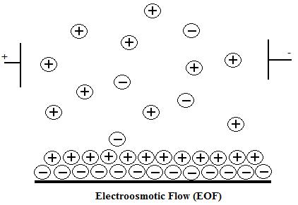
Electroosmotic Flow
The electroosmotic flow (EOF) is caused by applying high-voltage to an electrolyte-filled capillary.4 This flow occurs when the buffer running through the silica capillary has a pH greater than 3 and the SiOH groups lose a proton to become SiO- ions. The capillary wall then has a negative charge, which develops a double layer of cations attracted to it. The inner cation layer is stationary, while the outer layer is free to move along the capillary. The applied electric field causes the free cations to move toward the cathode creating a powerful bulk flow. The rate of the electroosmotic flow is governed by the following equation:
\[ \mu_{EOF} = \dfrac{\epsilon}{4\pi\eta} E\zeta \label{3} \]
where ε is the dielectric constant of the solution, η is the viscosity of the solution, E is the field strength, and ζ is the zeta potential. Because the electrophoretic mobility is greater than the electroosmotic flow, negatively charged particles, which are naturally attracted to the positively charged anode, will separate out as well. The EOF works best with a large zeta potential between the cation layers, a large diffuse layer of cations to drag more molecules towards the cathode, low resistance from the surrounding solution, and buffer with pH of 9 so that all the SiOH groups are ionized.1
Capillary Electroseparation Methods
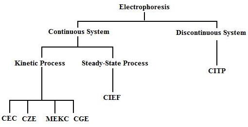
There are six types of capillary electroseparation available: capillary zone electrophoresis (CZE), capillary gel electrophoresis (CGE), micellar electrokinetic capillary chromatography (MEKC), capillary electrochromatography (CEC), capillary isoelectric focusing (CIEF), and capillary isotachophoresis (CITP). They can be classified into continuous and discontinuous systems as shown in Figure 3. A continuous system has a background electrolyte acting throughout the capillary as a buffer. This can be broken down into kinetic (constant electrolyte composition) and steady-state (varying electrolyte composition) processes. A discontinuous system keeps the sample in distinct zones separated by two different electrolytes.6
Capillary Zone Electrophoresis (CZE)
Capillary Zone Electrophoresis (CZE), also known as free solution capillary electrophoresis, it is the most commonly used technique of the six methods.A mixture in a solution can be separated into its individual components quickly and easily.The separation is based on the differences in electrophoretic mobility, which is directed proportional to the charge on the molecule, and inversely proportional to the viscosity of the solvent and radius of the atom.The velocity at which the ion moves is directly proportional to the electrophoretic mobility and the magnitude of the electric field.1
The fused silica capillaries have silanol groups that become ionized in the buffer. The negatively charged SiO- ions attract positively charged cations, which form two layers—a stationary and diffuse cation layer. In the presence of an applied electric field, the diffuse layer migrates towards the negatively charged cathode creating an electrophoretic flow (\(\mu_{ep}\)) that drags bulk solvent along with it. Anions in solution are attracted to the positively charged anode, but get swept to the cathode as well. Cations with the largest charge-to-mass ratios separate out first, followed by cations with reduced ratios, neutral species, anions with smaller charge-to-mass ratios, and finally anions with greater ratios. The electroosmotic velocity can be adjusted by altering pH, the viscosity of the solvent, ionic strength, voltage, and the dielectric constant of the buffer.1
Capillary Gel Electrophoresis (CGE)
CGE uses separation based on the difference in solute size as the particles migrate through the gel. Gels are useful because they minimize solute diffusion that causes zone broadening, prevent the capillary walls from absorbing the solute, and limit the heat transfer by slowing down the molecules. A commonly used gel apparatus for the separation of proteins is capillary SDS-PAGE. It is a highly sensitive system and only requires a small amount of sample.1
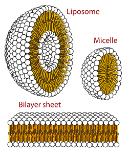
Micellar Electrokinetic Capillary Chromatography (MEKC)
MEKC is a separation technique that is based on solutes partitioning between micelles and the solvent. Micelles are aggregates of surfactant molecules that form when a surfactant is added to a solution above the critical micelle concentration. The aggregates have polar negatively charged surfaces and are naturally attracted to the positively charged anode. Because of the electroosmotic flow toward the cathode, the micelles are pulled to the cathode as well, but at a slower rate. Hydrophobic molecules will spend the majority of their time in the micelle, while hydrophilic molecules will migrate quicker through the solvent. When micelles are not present, neutral molecules will migrate with the electroosmotic flow and no separation will occur. The presence of micelles results in a retention time to where the solute has little micelle interaction and retention time tmc where the solute strongly interacts. Neutral molecules will be separated at a time between to and tmc. Factors that affect the electroosmotic flow in MEKC are: pH, surfactant concentration, additives, and polymer coatings of the capillary wall.1
Capillary Electrochromatography (CEC)
The separation mechanism is a packed column similar to chromatography. The mobile liquid passes over the silica wall and the particles. An electroosmosis flow occurs because of the charges on the stationary surface. CEC is similar to CZE in that they both have a plug-type flow compared to the pumped parabolic flow that increases band broadening.1
Capillary Isoelectric Focusing (CIEF)
CIEF is a technique commonly used to separate peptides and proteins. These molecules are called zwitterionic compounds because they contain both positive and negative charges. The charge depends on the functional groups attached to the main chain and the surrounding pH of the environment. In addition, each molecule has a specific isoelectric point (pI). When the surrounding pH is equal to this pI, the molecule carries no net charge. To be clear, it is not the pH value where a protein has all bases deprotonated and all acids protonated, but rather the value where positive and negative charges cancel out to zero. At a pH below the pI, the molecule is positive, and then negative when the pH is above the pI. Because the charge changes with pH, a pH gradient can be used to separate molecules in a mixture. During a CIEF separation, the capillary is filled with the sample in solution and typically no EOF is used (EOF is removed by using a coated capillary). When the voltage is applied, the ions will migrate to a region where they become neutral (pH=pI). The anodic end of the capillary sits in acidic solution (low pH), while the cathodic end sits in basic solution (high pH). Compounds of equal isoelectric points are “focused” into sharp segments and remain in their specific zone, which allows for their distinct detection.6
Calculating pI
An amino acid with n ionizable groups with their respective pKa values pK1, pK2, ... pkn will have the pI equal to the average of the group pkas: pI = (pK1+pK2+...+pkn)/n. Most proteins have many ionizable sidechains in addition to their amino- and carboxy- terminal groups. The pI is different for each protein and it can be theoretically calculated according to the Henderson-Hasselbalch approximation, if we know amino acids composition of protein. In order to experimentally determine a protein's pI 2-Dimensional Electrophoresis (2-DE) can be used. The proteins of a cell lysate are applied to a pH immobilized gradient strip, upon electrophoresis the proteins migrate to their pI within the strip. The second dimension of 2-DE is the separation of proteins by MW using a SDS-gel.
Capillary Isotachorphoresis (CITP)
CITP is the only method to be used in a discontinuous system. The analyte migrates in consecutive zones and each zone length can be measured to find the quantity of sample present.1
Capillary Electrophoresis versus High Performance Liquid Chromatography (HPLC)
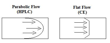
- CE has a flat flow, compared to the pumped parabolic flow of the HPLC. The flat flow results in narrower peaks and better resolution (Figure \(\PageIndex{4}\)).
- CE has a greater peak capacity when compared to HPLC—CE uses millions of theoretical plates.
- HPLC is more thoroughly developed and has many mobile and stationary phases that can be implemented.
- HPLC has more complex instrumentation, while CE is simpler for the operator.
- HPLC has such a wide variety of column lengths and packing, whereas CE is limited to thin capillaries.
- Both techniques use similar modes of detection.
- Can be used complementary to one another.
Problems
- Calculate µEP if q= +1, η is 3.7 (lb s/ft2) x 10-5 and the radius of the atom is 2 nm.
- How does buffer pH affect the capillary?
- How does hydrophilicity affect MEKC?
- What advantages does capillary electrophoresis provide over liquid chromatography?
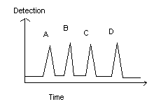
- Give reasons why “Analyte A” migrated first, while “Analyte D” migrated last.
References
- Li, Sam. Capillary Electrophoresis: Principles, Practice, and Applications. Journal of Chromatography Library; Elsevier Science Publishers: The Netherlands, 1992; Vol 52.
- Petersen, John R., and Amin A. Mohammad, eds. Clinical and Forensic Applications of Capillary Electrophoresis. New York: Humana P, 2001.
- Camilleri, Patrick. Capillary Electrophoresis. New York: C R C P LLC, 1997.
- Altria, Kevin D., Capillary Electrophoresis Guidebook : Principles, Operation and Applications. New York: Humana P, 1995.
- Landers, James P., Handbook of Capillary Electrophoresis. New York: C R C P LLC, 1996.
- Weston, A.; Brown, P. HPLC and CE: Principles and Practice; Academic Press: San Diego, 1997.