Lab 4: Gas Chromatography
- Page ID
- 2377
\( \newcommand{\vecs}[1]{\overset { \scriptstyle \rightharpoonup} {\mathbf{#1}} } \)
\( \newcommand{\vecd}[1]{\overset{-\!-\!\rightharpoonup}{\vphantom{a}\smash {#1}}} \)
\( \newcommand{\id}{\mathrm{id}}\) \( \newcommand{\Span}{\mathrm{span}}\)
( \newcommand{\kernel}{\mathrm{null}\,}\) \( \newcommand{\range}{\mathrm{range}\,}\)
\( \newcommand{\RealPart}{\mathrm{Re}}\) \( \newcommand{\ImaginaryPart}{\mathrm{Im}}\)
\( \newcommand{\Argument}{\mathrm{Arg}}\) \( \newcommand{\norm}[1]{\| #1 \|}\)
\( \newcommand{\inner}[2]{\langle #1, #2 \rangle}\)
\( \newcommand{\Span}{\mathrm{span}}\)
\( \newcommand{\id}{\mathrm{id}}\)
\( \newcommand{\Span}{\mathrm{span}}\)
\( \newcommand{\kernel}{\mathrm{null}\,}\)
\( \newcommand{\range}{\mathrm{range}\,}\)
\( \newcommand{\RealPart}{\mathrm{Re}}\)
\( \newcommand{\ImaginaryPart}{\mathrm{Im}}\)
\( \newcommand{\Argument}{\mathrm{Arg}}\)
\( \newcommand{\norm}[1]{\| #1 \|}\)
\( \newcommand{\inner}[2]{\langle #1, #2 \rangle}\)
\( \newcommand{\Span}{\mathrm{span}}\) \( \newcommand{\AA}{\unicode[.8,0]{x212B}}\)
\( \newcommand{\vectorA}[1]{\vec{#1}} % arrow\)
\( \newcommand{\vectorAt}[1]{\vec{\text{#1}}} % arrow\)
\( \newcommand{\vectorB}[1]{\overset { \scriptstyle \rightharpoonup} {\mathbf{#1}} } \)
\( \newcommand{\vectorC}[1]{\textbf{#1}} \)
\( \newcommand{\vectorD}[1]{\overrightarrow{#1}} \)
\( \newcommand{\vectorDt}[1]{\overrightarrow{\text{#1}}} \)
\( \newcommand{\vectE}[1]{\overset{-\!-\!\rightharpoonup}{\vphantom{a}\smash{\mathbf {#1}}}} \)
\( \newcommand{\vecs}[1]{\overset { \scriptstyle \rightharpoonup} {\mathbf{#1}} } \)
\( \newcommand{\vecd}[1]{\overset{-\!-\!\rightharpoonup}{\vphantom{a}\smash {#1}}} \)
\(\newcommand{\avec}{\mathbf a}\) \(\newcommand{\bvec}{\mathbf b}\) \(\newcommand{\cvec}{\mathbf c}\) \(\newcommand{\dvec}{\mathbf d}\) \(\newcommand{\dtil}{\widetilde{\mathbf d}}\) \(\newcommand{\evec}{\mathbf e}\) \(\newcommand{\fvec}{\mathbf f}\) \(\newcommand{\nvec}{\mathbf n}\) \(\newcommand{\pvec}{\mathbf p}\) \(\newcommand{\qvec}{\mathbf q}\) \(\newcommand{\svec}{\mathbf s}\) \(\newcommand{\tvec}{\mathbf t}\) \(\newcommand{\uvec}{\mathbf u}\) \(\newcommand{\vvec}{\mathbf v}\) \(\newcommand{\wvec}{\mathbf w}\) \(\newcommand{\xvec}{\mathbf x}\) \(\newcommand{\yvec}{\mathbf y}\) \(\newcommand{\zvec}{\mathbf z}\) \(\newcommand{\rvec}{\mathbf r}\) \(\newcommand{\mvec}{\mathbf m}\) \(\newcommand{\zerovec}{\mathbf 0}\) \(\newcommand{\onevec}{\mathbf 1}\) \(\newcommand{\real}{\mathbb R}\) \(\newcommand{\twovec}[2]{\left[\begin{array}{r}#1 \\ #2 \end{array}\right]}\) \(\newcommand{\ctwovec}[2]{\left[\begin{array}{c}#1 \\ #2 \end{array}\right]}\) \(\newcommand{\threevec}[3]{\left[\begin{array}{r}#1 \\ #2 \\ #3 \end{array}\right]}\) \(\newcommand{\cthreevec}[3]{\left[\begin{array}{c}#1 \\ #2 \\ #3 \end{array}\right]}\) \(\newcommand{\fourvec}[4]{\left[\begin{array}{r}#1 \\ #2 \\ #3 \\ #4 \end{array}\right]}\) \(\newcommand{\cfourvec}[4]{\left[\begin{array}{c}#1 \\ #2 \\ #3 \\ #4 \end{array}\right]}\) \(\newcommand{\fivevec}[5]{\left[\begin{array}{r}#1 \\ #2 \\ #3 \\ #4 \\ #5 \\ \end{array}\right]}\) \(\newcommand{\cfivevec}[5]{\left[\begin{array}{c}#1 \\ #2 \\ #3 \\ #4 \\ #5 \\ \end{array}\right]}\) \(\newcommand{\mattwo}[4]{\left[\begin{array}{rr}#1 \amp #2 \\ #3 \amp #4 \\ \end{array}\right]}\) \(\newcommand{\laspan}[1]{\text{Span}\{#1\}}\) \(\newcommand{\bcal}{\cal B}\) \(\newcommand{\ccal}{\cal C}\) \(\newcommand{\scal}{\cal S}\) \(\newcommand{\wcal}{\cal W}\) \(\newcommand{\ecal}{\cal E}\) \(\newcommand{\coords}[2]{\left\{#1\right\}_{#2}}\) \(\newcommand{\gray}[1]{\color{gray}{#1}}\) \(\newcommand{\lgray}[1]{\color{lightgray}{#1}}\) \(\newcommand{\rank}{\operatorname{rank}}\) \(\newcommand{\row}{\text{Row}}\) \(\newcommand{\col}{\text{Col}}\) \(\renewcommand{\row}{\text{Row}}\) \(\newcommand{\nul}{\text{Nul}}\) \(\newcommand{\var}{\text{Var}}\) \(\newcommand{\corr}{\text{corr}}\) \(\newcommand{\len}[1]{\left|#1\right|}\) \(\newcommand{\bbar}{\overline{\bvec}}\) \(\newcommand{\bhat}{\widehat{\bvec}}\) \(\newcommand{\bperp}{\bvec^\perp}\) \(\newcommand{\xhat}{\widehat{\xvec}}\) \(\newcommand{\vhat}{\widehat{\vvec}}\) \(\newcommand{\uhat}{\widehat{\uvec}}\) \(\newcommand{\what}{\widehat{\wvec}}\) \(\newcommand{\Sighat}{\widehat{\Sigma}}\) \(\newcommand{\lt}{<}\) \(\newcommand{\gt}{>}\) \(\newcommand{\amp}{&}\) \(\definecolor{fillinmathshade}{gray}{0.9}\)Gas chromatography is a physical method of separation in which the components to be separated are distributed between two phases, one being a stationary bed of large surface area, and the other a gas that percolates through the stationary bed. When the stationary phase is a solid, the separation process is more precisely called gas-solid chromatography.
Introduction
This technique is generally used to separate gases in a gaseous solution. The more common technique is gas-liquid chromatography in which the stationary phase is a porous solid covered with an absorbing liquid. Gas-liquid chromatography or GLC is used to separate a wide variety of organic compounds. The basic requirements for GLC are that the sample be volatile and that it not decompose in the vaporization process. Since the vaporization occurs in an inert atmosphere, decomposition of the sample is generally not a problem.
A basic chromatograph consists of the following:
- A sample port or injector for introduction and vaporization of the sample
- A separating column, consisting of metal tubing packed with a solid material coated with a stationary absorbing liquid
- A carrier gas, usually N2 or He, to sweep the sample through the column
- Flow control equipment to maintain a constant flow of carrier gas through the column
- The detector for measuring the quantity of a separated component
- Ovens and heaters for temperature control of the column, detector and injector
- An integrator or integrator/strip chart recorder combination to provide permanent record of the analysis
Separation of a mixture into its components depends on the solubility differences of the sample vapor in a liquid (stationary phase). The stationary phase is coated in a thin layer on solid particles (solid support) of large surface area and then packed uniformly into a column. A constant flow of an inert carrier gas passes through the column and transports solute molecules in the gas phase. The column is enclosed by an oven for precise temperature control.
A sample of the analyte is introduced by syringe injection into the heated injector tube, where it is vaporized and mixed with the carrier gas. As the sample vapor/carrier gas mixture flows onto the column, the analyte partitions between the gas and liquid phases according to the analyte component's solubility in the liquid at the column operating temperature. This equilibrium partitioning continues as the sample is moved through the column by the carrier gas. The rate at which the sample travels through the column is determined by the sample solubility in the stationary phase, the carrier gas flow rate, and the temperature gradient (temperature program) applied. Each component travels at a characteristic rate, and if the column has sufficient length and resolving power, the sample will be completely separated by the time it reaches the detector.
The Thermal Conductivity Detector (TCD), located at the column exit, senses any change in the physical or chemical properties of the column effluent compared to the reference column effluent. The deflection from the baseline observed indicates the presence and concentration of a component, but does not identify it. A detailed description of how the TCD works can be found in section 27-B4 of your text, Principles of Instrumental Analysis.
Each component is identified by comparing its "retention time", the length of time that it remains in the column, to that of a standard. The retention time of a vapor depends on the column temperature limits and ramp rate, the column length, type of stationary phase, and carrier gas velocity. If these variables are kept constant, the retention time of a component will remain constant, and therefore a component may be tentatively identified by the measurement of its retention time which is compared to the retention time of a known standard run under identical operating conditions.
Retention time is reported on the processed data file print out following the chromatogram on the integrator chart. The sample components are represented as peaks on the chromatogram. The detector produces an electrical output that is proportional to vapor concentration which results in pen deflection on the integrator chart recorder. The chart paper on the integrator moves at a constant speed, providing a plot of time versus the composition of the column effluent. The distance between two successive peaks is a measure of the difference in retention time of the analyte components.
If the response of the detector is linear, the area under a peak accurately represents the quantity of the component present. If it is not, calibration for detector response to the types of components expected to be in the analyte yields a set of response factors that convert the reported area percentages to quantitative weight percentages. This is necessary for TCD use. The flame ionization detector (FID), (see McNair and Bonelli) has a linear response to a homologous series of components but also requires response factors for accurate quantitation when different types of components are present.
For a given gas chromatography column, the Van Deemter theory is useful for determining the flow rate which gives optimum efficiency at a given column temperature for a particular compound. The Van Deemter equation is
\[ HETP = A + \dfrac{B}{v} + C_v \; \; (1) \]
where A, B, and C are constants and v is the carrier gas flow rate. HETP is the "height equivalent to a theoretical plate", and results from the treatment of gas chromatographic separations in terms of repeated equilibrations between a moving and a stationary phase. HETP for a particular gas flow rate is calculated from the total number of theoretical plates (N) and column length (L), i.e.
\[ HETP = \dfrac{L}{N} \; \; (2) \]
where
\[N = 16 \left( \dfrac{t_r}{w} \right)^2 \label{3}\]
where tr is the retention of the component and w is the width of the elution peak at its base. The first term in the Van Deemter equation accounts for eddy diffusion, the second term accounts for molecular diffusion, and the third term accounts for non equilibrium effects due to flow of the mobile phase. For a particular column at constant temperature, the optimum carrier gas flow rate is that for which the HETP is a minimum. By measuring the HETP at several linear gas velocities (flow rates), the parameters A, B, and C in Equation \(\ref{1}\) can be determined and the optimum velocity defined.
If the sample contains materials with a wide range of boiling points, separation of all components isothermally is not practical. When the column is operated at low temperatures, the more volatile components will be distributed between the gas and liquid phases and will pass rapidly through the column giving sharp well resolved peaks. The high boiling components, however, will remain dissolved in the stationary phase and will be eluted very slowly, if at all. Since the vapor pressure of the latter solutes is low, partitioning will occur over a large bands of stationary phase resulting in broad poorly resolved peaks.
If the column is operated at a temperature that gives well defined peaks for the less volatile components, the low boiling fraction will pass through the column with very little partitioning into the liquid phase. As a result, it will appear as one or two sharp yet poorly resolved peaks, often with retention volumes approaching the dead space of the column.
Although temperature programming will not be performed in this laboratory, it is a useful feature that allows all the compounds to be eluted at temperatures approximating the ideal temperature for separation from adjacent solutes. By employing a low initial temperature, the low boiling components will be distributed between both phases in the column and will appear at the detector as sharp, well-resolved bands. The higher boiling fractions will remain 'frozen' at the injection point. As the column temperature is raised, the vapor pressure of the less volatile components will increase and they will distribute themselves between the two phases and, as a result, move down as well-defined bands, eluting at characteristic temperatures. By careful choice of the temperature ramp rate and carrier gas flow rate, each component can be eluted at a temperature approximating the optimum for separation from adjacent solutes. Although the resolution of closely spaced peaks cannot be improved over that obtained at a single optimum temperature, the resolution of widely spaced peaks can be improved considerably.
The Instrumentation
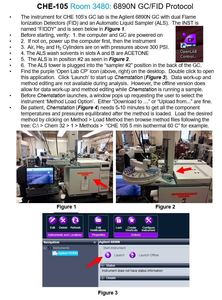
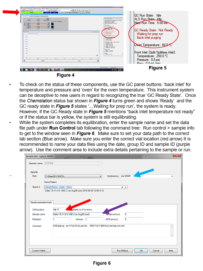
The instrument used in this experiment is an Agilent 6890N gas chromatograph equipped with with an Automatic Liquid Sampler (ALS) that will allow the injection to be controled by automation through the software. Inside the GC oven in position #2 is a high efficiency J&W CP-Sil 5 CB fused silica column containing a 100% dimethylpolysiloxane phase. This 15 m column has an 0.25 mm internal diameter and with a 0.25 µm thick internal coating. PLEASE, Do not use the front column.
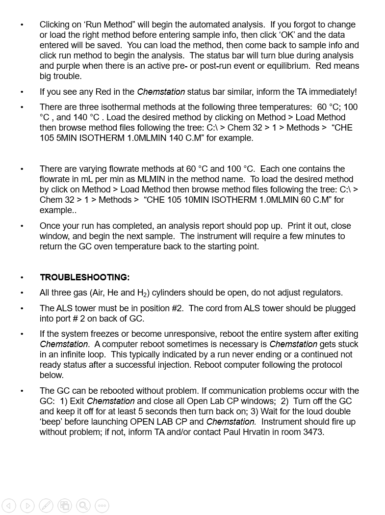
Temperature control for the injector, detector, and column is set through software. You will only need to change the column temperature for this experiment. The flow is built into the method and is included in the method name. Do not edit or alter a method’s flow rate, instead switch methods and choose a method with flow rate desired. Pressing ‘status’ button on GC front panel will indicate flow rates and other instrument equilibrium activities like temperature and flame status.

Experimental
1. Isothermal Gas Chromatography of an Homologous Series
Run an isothermal (100 °C) gas chromatogram of each of the C6 to C11 n-alkanes (2-3 uL sample) at varying flow rates. Make sure ALS in above port 2. Record carefully the retention time of each compound.
Plot log r vs carbon number and log r vs boiling point of the n-alkanes. (Why use log r?) (Be sure to look up the boiling points before you do the experiment). Which plot provides the best straight-line relationship?
Run a GC of 2,2,4-trimethylpentane under the same conditions. Compare its retention time and boiling point with n-octane. On the basis of boiling point data, predict retention times for the two other isomers in this series - 2,2-dimethylhexane and 2-methylheptane. Comment on whether these would or would not be expected to resolve using the instrument settings in this section.
2. Effects of Column Temperature
Do a combined injection (see your TA for the technique) of C7, C9, C11 and C6, C8, C10 mixture at 60, 100, and 140°C.
Discuss the expected and observed effects that temperature has on gas chromatographic behavior. Is one temperature suitable for separation of this mixture?
For each component plot log r vs 1/T where T is temperature in K. Briefly discuss this plot.
3. Effects of Carrier Gas Flow Rate
In this experiment you will investigate the effect of the gas flow rate on the retention time. Run isothermal chromatograms of n-heptane at flow rates of (approximately) 1.0, 1.5 and 2.0 mL/min (you need not get these values exactly but you must know the flow rate precisely. Use the temperature that gave you the best resolution of all 5 alkanes determined in parts 1 and 2). In each case calculate N and HETP. Tabulate and plot your results. Also run n-hexane at flow rates of 2.0 and 4.0 mL/min and measure N and HETP as before. Ask your TA or Paul for help if you have any questions.
4. The Unknown
In parts 1-3 of this experiment you determined the optimum conditions for the separation of the C6-C11n-alkanes. Now use these conditions to identify the unknown mixture of these alkanes. Run your C6-C11 n-alkane standards under your best conditions. You can run them in 2 or 3 batches as mixtures. Then run the unknown sample under the same conditions. Identify the components of the unknown mixture by comparison with the standards.
References
- H. M. McNair and E. J. Bonelli, "Basic Gas Chromatography", Varian Instruments, Palo Alto, CA., March 1969, pp. 91-99.
- D.A. Skoog, F.J. Holler and T.A. Nieman, "Principles of Instrumental Analysis, Fifth Edition", Harcourt Brace and Company, Philadelphia, PA, 1998, pp 701- 724.


