2.5: Coordination Numbers and Structures
- Last updated
- Save as PDF
- Page ID
- 429157
\( \newcommand{\vecs}[1]{\overset { \scriptstyle \rightharpoonup} {\mathbf{#1}} } \)
\( \newcommand{\vecd}[1]{\overset{-\!-\!\rightharpoonup}{\vphantom{a}\smash {#1}}} \)
\( \newcommand{\id}{\mathrm{id}}\) \( \newcommand{\Span}{\mathrm{span}}\)
( \newcommand{\kernel}{\mathrm{null}\,}\) \( \newcommand{\range}{\mathrm{range}\,}\)
\( \newcommand{\RealPart}{\mathrm{Re}}\) \( \newcommand{\ImaginaryPart}{\mathrm{Im}}\)
\( \newcommand{\Argument}{\mathrm{Arg}}\) \( \newcommand{\norm}[1]{\| #1 \|}\)
\( \newcommand{\inner}[2]{\langle #1, #2 \rangle}\)
\( \newcommand{\Span}{\mathrm{span}}\)
\( \newcommand{\id}{\mathrm{id}}\)
\( \newcommand{\Span}{\mathrm{span}}\)
\( \newcommand{\kernel}{\mathrm{null}\,}\)
\( \newcommand{\range}{\mathrm{range}\,}\)
\( \newcommand{\RealPart}{\mathrm{Re}}\)
\( \newcommand{\ImaginaryPart}{\mathrm{Im}}\)
\( \newcommand{\Argument}{\mathrm{Arg}}\)
\( \newcommand{\norm}[1]{\| #1 \|}\)
\( \newcommand{\inner}[2]{\langle #1, #2 \rangle}\)
\( \newcommand{\Span}{\mathrm{span}}\) \( \newcommand{\AA}{\unicode[.8,0]{x212B}}\)
\( \newcommand{\vectorA}[1]{\vec{#1}} % arrow\)
\( \newcommand{\vectorAt}[1]{\vec{\text{#1}}} % arrow\)
\( \newcommand{\vectorB}[1]{\overset { \scriptstyle \rightharpoonup} {\mathbf{#1}} } \)
\( \newcommand{\vectorC}[1]{\textbf{#1}} \)
\( \newcommand{\vectorD}[1]{\overrightarrow{#1}} \)
\( \newcommand{\vectorDt}[1]{\overrightarrow{\text{#1}}} \)
\( \newcommand{\vectE}[1]{\overset{-\!-\!\rightharpoonup}{\vphantom{a}\smash{\mathbf {#1}}}} \)
\( \newcommand{\vecs}[1]{\overset { \scriptstyle \rightharpoonup} {\mathbf{#1}} } \)
\( \newcommand{\vecd}[1]{\overset{-\!-\!\rightharpoonup}{\vphantom{a}\smash {#1}}} \)
\(\newcommand{\avec}{\mathbf a}\) \(\newcommand{\bvec}{\mathbf b}\) \(\newcommand{\cvec}{\mathbf c}\) \(\newcommand{\dvec}{\mathbf d}\) \(\newcommand{\dtil}{\widetilde{\mathbf d}}\) \(\newcommand{\evec}{\mathbf e}\) \(\newcommand{\fvec}{\mathbf f}\) \(\newcommand{\nvec}{\mathbf n}\) \(\newcommand{\pvec}{\mathbf p}\) \(\newcommand{\qvec}{\mathbf q}\) \(\newcommand{\svec}{\mathbf s}\) \(\newcommand{\tvec}{\mathbf t}\) \(\newcommand{\uvec}{\mathbf u}\) \(\newcommand{\vvec}{\mathbf v}\) \(\newcommand{\wvec}{\mathbf w}\) \(\newcommand{\xvec}{\mathbf x}\) \(\newcommand{\yvec}{\mathbf y}\) \(\newcommand{\zvec}{\mathbf z}\) \(\newcommand{\rvec}{\mathbf r}\) \(\newcommand{\mvec}{\mathbf m}\) \(\newcommand{\zerovec}{\mathbf 0}\) \(\newcommand{\onevec}{\mathbf 1}\) \(\newcommand{\real}{\mathbb R}\) \(\newcommand{\twovec}[2]{\left[\begin{array}{r}#1 \\ #2 \end{array}\right]}\) \(\newcommand{\ctwovec}[2]{\left[\begin{array}{c}#1 \\ #2 \end{array}\right]}\) \(\newcommand{\threevec}[3]{\left[\begin{array}{r}#1 \\ #2 \\ #3 \end{array}\right]}\) \(\newcommand{\cthreevec}[3]{\left[\begin{array}{c}#1 \\ #2 \\ #3 \end{array}\right]}\) \(\newcommand{\fourvec}[4]{\left[\begin{array}{r}#1 \\ #2 \\ #3 \\ #4 \end{array}\right]}\) \(\newcommand{\cfourvec}[4]{\left[\begin{array}{c}#1 \\ #2 \\ #3 \\ #4 \end{array}\right]}\) \(\newcommand{\fivevec}[5]{\left[\begin{array}{r}#1 \\ #2 \\ #3 \\ #4 \\ #5 \\ \end{array}\right]}\) \(\newcommand{\cfivevec}[5]{\left[\begin{array}{c}#1 \\ #2 \\ #3 \\ #4 \\ #5 \\ \end{array}\right]}\) \(\newcommand{\mattwo}[4]{\left[\begin{array}{rr}#1 \amp #2 \\ #3 \amp #4 \\ \end{array}\right]}\) \(\newcommand{\laspan}[1]{\text{Span}\{#1\}}\) \(\newcommand{\bcal}{\cal B}\) \(\newcommand{\ccal}{\cal C}\) \(\newcommand{\scal}{\cal S}\) \(\newcommand{\wcal}{\cal W}\) \(\newcommand{\ecal}{\cal E}\) \(\newcommand{\coords}[2]{\left\{#1\right\}_{#2}}\) \(\newcommand{\gray}[1]{\color{gray}{#1}}\) \(\newcommand{\lgray}[1]{\color{lightgray}{#1}}\) \(\newcommand{\rank}{\operatorname{rank}}\) \(\newcommand{\row}{\text{Row}}\) \(\newcommand{\col}{\text{Col}}\) \(\renewcommand{\row}{\text{Row}}\) \(\newcommand{\nul}{\text{Nul}}\) \(\newcommand{\var}{\text{Var}}\) \(\newcommand{\corr}{\text{corr}}\) \(\newcommand{\len}[1]{\left|#1\right|}\) \(\newcommand{\bbar}{\overline{\bvec}}\) \(\newcommand{\bhat}{\widehat{\bvec}}\) \(\newcommand{\bperp}{\bvec^\perp}\) \(\newcommand{\xhat}{\widehat{\xvec}}\) \(\newcommand{\vhat}{\widehat{\vvec}}\) \(\newcommand{\uhat}{\widehat{\uvec}}\) \(\newcommand{\what}{\widehat{\wvec}}\) \(\newcommand{\Sighat}{\widehat{\Sigma}}\) \(\newcommand{\lt}{<}\) \(\newcommand{\gt}{>}\) \(\newcommand{\amp}{&}\) \(\definecolor{fillinmathshade}{gray}{0.9}\)Why do coordination complexes form the structures they do?
As with all chemical structure, coordination complexes form the structures they do so as to best stabilize the metal center and ligands through the formation of metal-ligand bonds while avoiding destabilizing interactions like steric repulsions. The issue then is how many metal-ligand bonds should be formed and how those bonds should be arranged spatially to give the largest net stabilization possible. This question will eventually be considered in detail in connection with the nature of bonding in coordination compounds. For now, it will be helpful to think about it in terms of seven factors:
The stabilizing effect of metal-ligand bond formation.
The driving force for complex formation is the stabilization of electrons in covalent chemical bonds. In the vast majority of cases, this largely involves stabilization of the ligand lone pair as it experiences the effective nuclear charge of the metal, although a few instances involve stabilization of metal electrons by ligand nuclei (inverse ligand fields). Regardless, metal-ligand bond formation is stabilizing and classified by the way it preferences the addition of ligands to the complex.
Steric effects, specifically steric repulsions between ligands.
One reason coordination numbers do not increase indefinitely is that only so many ligands can fit around a metal. Exactly how many depends on
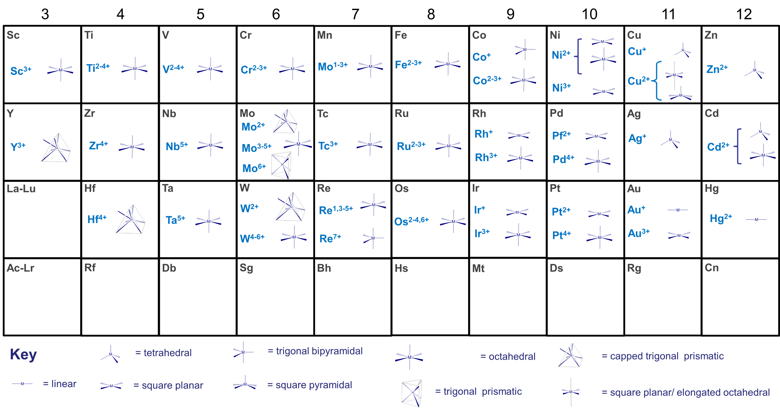
- the size of the metal center. This is one of the more important factors. Many metals tend to exhibit preferred coordination numbers, which depend on their oxidation state and size as shown in Figure \(\sf{\PageIndex{1}}\). Larger inner transition metals like the Lanthanides and Actinides can accommodate 9-12 sterically undemanding ligands, while the smaller transition metals tend to accommodate up to six, although larger coordination numbers are more common for low valent metals and as size increases on moving from right to left across the transition metal block of the periodic table. Thus, the early transition metal molybdenum forms seven- and eight-coordinate [MoIII(CN)7]4- and [MoIV(CN)8]4- with the sterically undemanding cyano ligand.
- the size of the ligands. As long as ligands are not excessively rigid and bulky, their size is less important than the size of the metal in determining the number of ligands that coordinate. Ligands' ability to donate electrons to the metal center also tends to influence coordination number more than ligand size. However, all other things being equal for a given metal and ligand donor ability, small ligands allow higher coordination numbers while fewer bulky ligands will fit around the metal center.
- how the ligand bonds to the metal. Again, all other things being equal, ligands that are more sterically demanding in the vicinity of the metal center tend to limit the ability of other ligands to bind more than those which bind through a small extended group. For example, a bulky isocyanide like t-BuCN will sterically crowd the metal less than a bulky phosphine like t-BuH2P would. For this reason the effective size of a ligand is sometimes rated in terms of either a cone angle of space they are estimated to occupy around the metal (called the Tolman cone angle, it is commonly used to evaluate phosphines' steric bulk) or in terms of the percentage of the metal's coordination sphere the ligand occupies (called the percent buried volume, it is used to estimate the steric impact of N-heterocyclic carbenes).
Repulsion between M-L bonding electrons on different ligands.
For many complexes, steric effects are neither the only effects nor the most important. Among the additional factors that should be considered are the repulsions that occur between the electrons that different ligands donate to the metal-ligand bonding. These electron-electron repulsions affect the
- Coordination number. When a ligand donates its electrons to a metal center to form a new metal-ligand bond, the electron density around the metal increases, raising the overall energy of the other M-L bonding electrons. This increased repulsion often limits the number of coordinated ligands. As more ligands are added, the electron-electron repulsions keep increasing until the lowering of energy of the ligand electrons in the new bond is insufficient to compensate for the raising of energy of the existing M-L bonding electrons. Based on this effect alone,
- larger metals tend to achieve higher coordination numbers than smaller ones because the electron-electron repulsions are spread across a larger coordination sphere.
- With a given metal, ligands that are more electron donating have a greater tendency to form complexes with lower coordination numbers with a given metal than similar neutral ones do. This is why anionic ligands (which tend to be better electron donors) tend to give lower coordination numbers than comparable neutral ligands (which tend to be weaker donors). Thus Co2+ forms CoCl42- with chloro ligands but [Co(H2O)6]2+ with aqua ligands.
- Coordination geometry. In the Kepert model for the shapes of coordination complexes, this intraligand repulsion determines the most stable coordination geometry by causing the ligands to move as far apart from one another on the metal's coordination sphere as possible.
Formally, according to the Kepert model
- any of the metal's valence electrons not involved in metal-ligand bonds occupy (n-1)d orbitals and function as core electrons. As core electrons they do not influence the molecular shape.
- electrons involved in bonding to a given ligand constitute an electron group that repels all other electron groups around the metal.
- all other things being equal, the complex will form the geometry that maximizes the intra-electron group repulsions.
Notice the similarities of these postulates to those of VSEPR theory. In predicting coordination geometries in terms of electron-electron repulsions, the Kepert model is just an extension of VSEPR theory to coordination compounds. The difference between VSEPR theory and the Kepert model is that in the Kepert model, only electrons involved in metal-ligand bonds count.
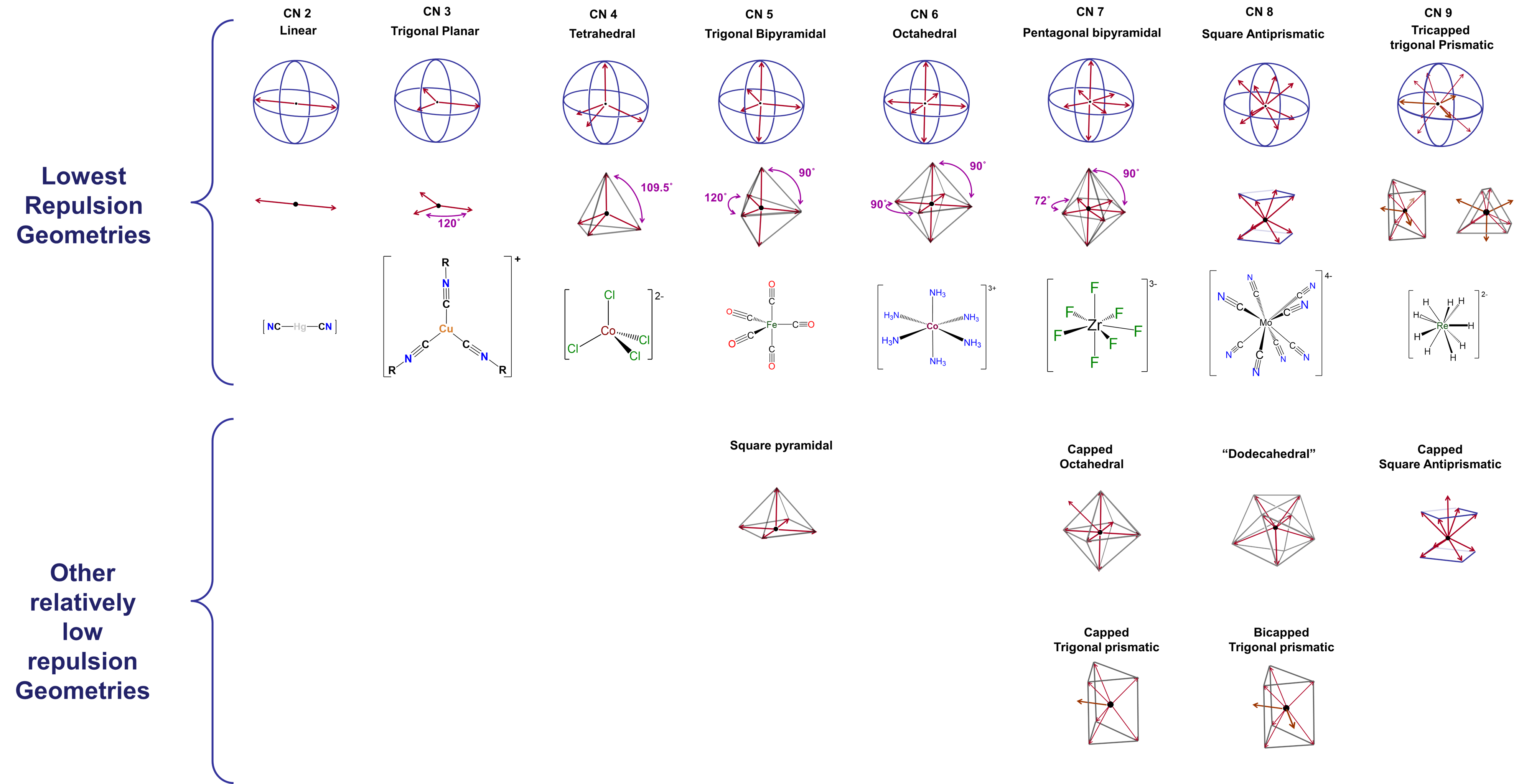
Coordination geometries predicted by the Kepert model for coordination numbers two through nine are given in Figure \(\sf{\PageIndex{2}}\). As may be seen from the geometries listed in Figure \(\sf{\PageIndex{2}}\), these are just equivalent to VSEPR geometries for cases in which the number of electron groups is equal to the coordination number.
The difference between optimal and suboptimal coordination geometries is greater with few ligands, and becomes smaller as ligands become increasingly dispersed across the metal's coordination sphere. In complexes containing five, seven, eight, or higher coordinate metals, there are a number of geometries that are similar in energy to the preferred geometry. These geometries, which should be regarded as accessible, are also listed in Figure \(\sf{\PageIndex{2}}\).
d-electron effects
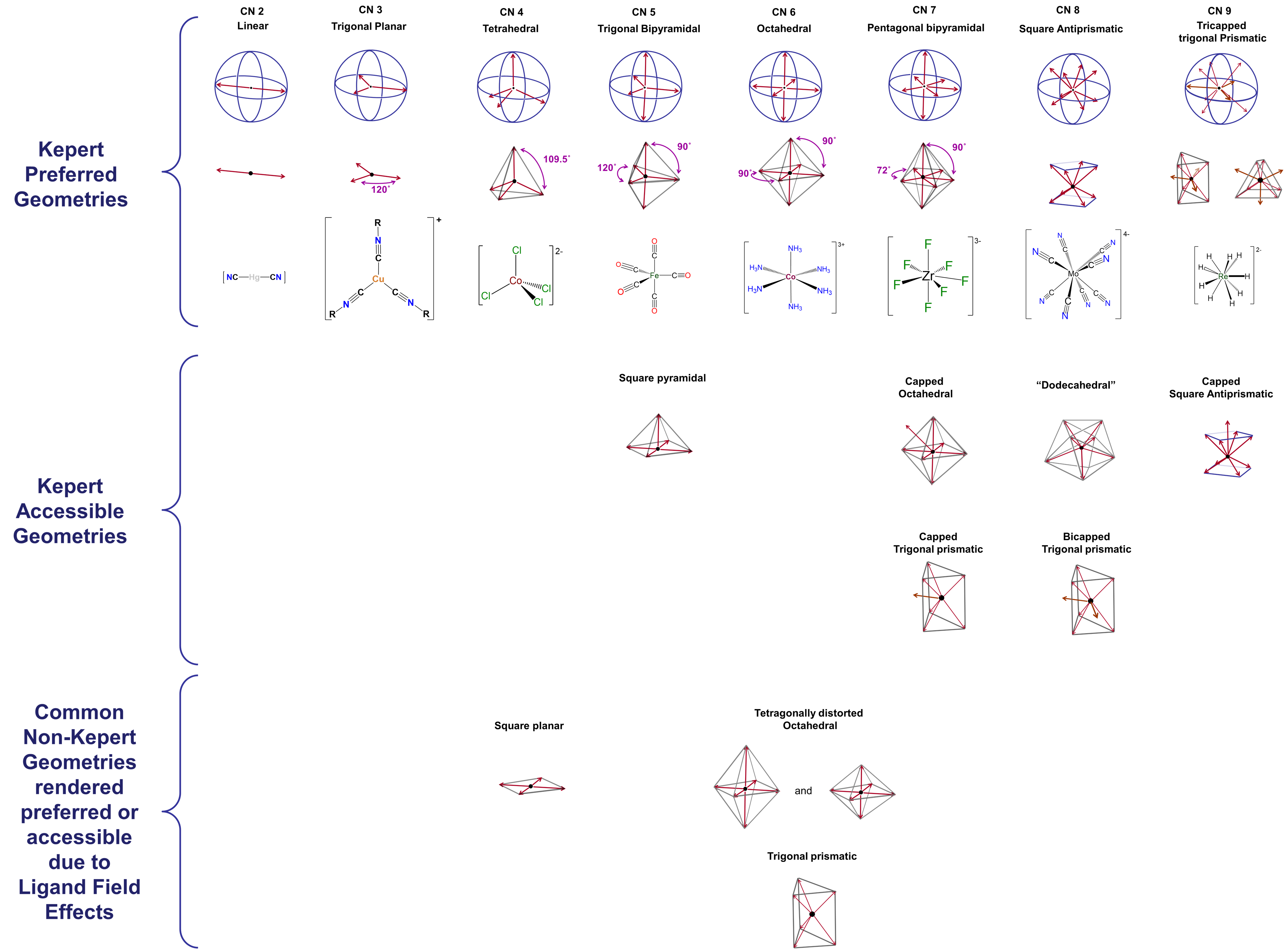
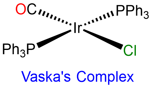
A few coordination geometries are noticeably absent from the Kepert-preferred and Kepert-accessible geometries in Figure \(\sf{\PageIndex{1}}\). These include the trigonal prismatic geometries formed by compounds like W(CH3)6 and the very common square planar geometry illustrated by complexes like [PtCl4]2- and [IrClH(PPh3)2]. One of the reasons the Kepert model fails to predict the existence of such structures is its neglect of directional interactions involving d electrons on the metal center. Metal d electrons exert a profound influence on almost all properties of transition metal complexes, including their structures. The way in which this occurs will be explored at length in the next chapter. For now, it is enough to note that both the ligand-donated electrons surrounding a metal center and the electrons occupying particular d orbitals on that metal are oriented in specific directions relative to one another. Because of this, the strength of the interactions between the ligand and metal d electrons depends on the number of d electrons present, how strongly metal-ligand binding affects their energy, and how the ligands are arranged about the metal center. The impact of these effects, here termed ligand field effects, differs from case to case and can include
- distortions of the complex's geometry. For instance, an ideal octahedral coordination geoemtry might be tetragonally distorted by flattening or elongating it.
- imparting a strong preference for non-Kepert coordination geometries. This is why, for example, 2nd and 3rd row complexes in which the metal has a d8 electron configuration are almost always square planar.
- stabilizing non-Kepert geometries enough to permit complexes to adopt them in the presence of a rigid or semirigid ligand that prefers to coordinate the metal in that geometry.3
Because of these effects, square planar and trigonal prismatic geometries are also observed, and the list of coordination geometries given in Figure \(\sf{\PageIndex{2}}\) may be extended to that shown in Figure \(\sf{\PageIndex{3}}\).
Ligand constraints imposed by rigid or semirigid ligands
Rigid or semirigid ligands influence the coordination geometry of metal complexes in two main ways:
- Bulky rigid ligands that crowd the metal center prevent other ligands from binding. Thus such ligands are useful for preparing low-coordinate complexes.
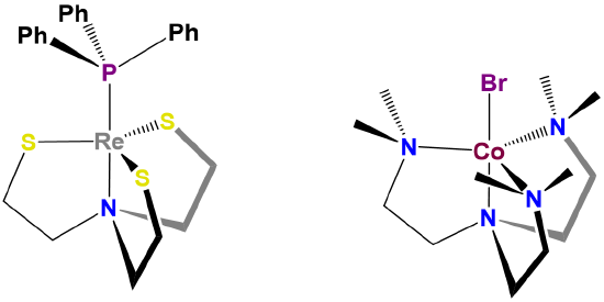
- Rigid and semirigid ligands can impose their preferred coordination geometry on a metal center. This is because these ligands energetically prefer to adopt a particular conformation when they bind a metal center. In doing so they shift the coordination geometry energy landscape toward that preferred geometry. If the shift is large enough relative to the native preference due to ligand repulsion and ligand field effects, the complex will either adopt the ligand-preferred geometry or be distorted in the direction of the ligand-preferred geometry. Examples are given in Figure \(\sf{\PageIndex{4}}\).

The influence of ligands on coordination geometry is important in living systems, in which proteins and nucleic acids can act as rigid or semirigid ligands. The ability of these ligands to distort the coordination geometries of metal atoms in ways that enable them to perform specific functions is so common that the resulting distorted geometries are termed entactic states. A particularly spectacular case of an entactic state involves the blue copper proteins azurin and plastocyanin, the structure of which is given in Figure \(\sf{\PageIndex{5}}\).
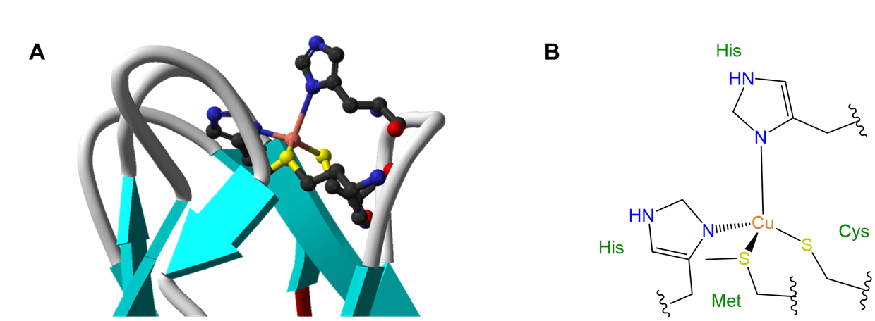
As may be seen from the structure in Figure \(\sf{\PageIndex{5}}\), the copper in plastocyanin exibits a distorted tetrahedral coordination geometry. The protein is said to act like a medieval torture device called a rack in stretching the metal into its distorted geometry. This distortion makes it easier for the copper center to undergo facile redox reactions, enabling it to better function as an electron carrier.
Crystal packing effects, in which the energy-lowering packing of molecules and ions in a crystal drives the distortion of a complex's structure away from what it would adopt in the gas phase or solution
This effect is similar to that of ligand constraints except that in this case it arises not from the structure internal to a ligand but out of the forces involves in maximizing the stabilization energy of a crystal. With lower coordination number complexes, packing effects can shift the conformations of flexible ligands but only give rise to very small distortions of the overall coordination geometry. Packing effects can drive a shift in the overall coordination geometry of higher coordination number complexes, for which packing effects are significant relative to the small difference in energy between geometries. Thus while [Mo(CN)8]4- has a square antiprismatic coordination geometry, in solution it exhibits a dodecahedral coordination geometry in the crystals of many of its salts.
Relativistic effects on orbital energies
The proximity of fast moving electrons to massive nuclei in the heavier transition elements results in relativistic expansion and contraction of orbitals. The net results are that
- heavier elements tend to be smaller than expected. This effect preferences lower coordination numbers.
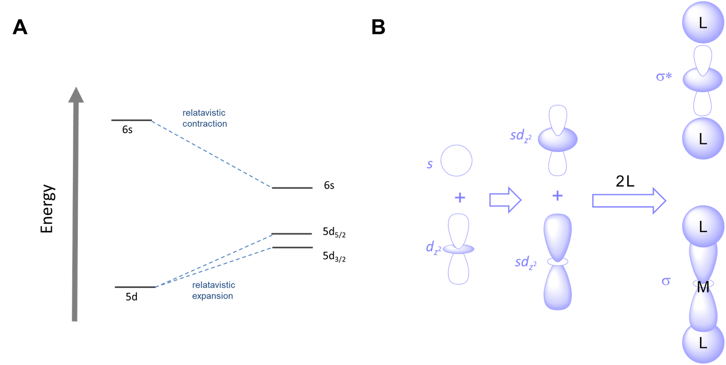
- the relative energies of orbitals shift. Orbitals which become contracted are lowered in energy while those which are expanded increase in energy, as shown for the case of gold in Figure \(\sf{\PageIndex{6A}}\).
The combination of smaller sizes and altered orbital energies affects coordination preferences. Relativistic effects contribute to the greater tendency of AuI relative to other group 11 metals to form linear two-coordinate complexes. As shown in Figure \(\sf{\PageIndex{6B}}\), the relative closeness in energy of the 6s and 5d orbitals of gold makes mixing of these orbitals more favorable, facilitating the ability of gold to form two-coordinate complexes with strong sigma bonds oriented 180/(^{\circ}\) from one another.
What structures do coordination complexes form?
Metal complexes with coordination numbers ranging from one to 16 are known, although values greater than seven are rare for the transition metals. In this section, examples of common coordination geometries will be presented in order of coordination number.
Coordination Number 1.
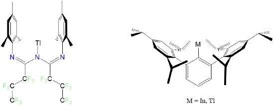
Condensed phase monocoordinate complexes are unknown for the transition metals, although the post-transition metals Tl and In form monocoordinate complexes with the bulky ligands triazapentadienyl and 2,6-tris(2,4,6-triisopropylphenyl)benzene as shown in Figure \(\sf{\PageIndex{7}}\).
Coordination Number 2.
A coordination number of 2 is rare outside of d10 complexes of the group 11 metals and mercury, specifically, Cu+, Ag+, Au+, and Hg2+. In accordance with the predictions of the Kepert model these give linear complexes.

Among these,
- Cu+ more commonly gives tetrahedral complexes but can be coaxed to give linear ones. The most prominent example is [CuCl2]-, which forms when CuCl is treated with concentrated HCl under anerobic conditions.
- Ag+ also commonly forms tetrahedral or trigonal planar complexes but can give linear ones. The most prominent example is [Ag(NH3)2]+, which can be formed by treating silver slats with concentrated aqueous or liquid ammonia.
- Au+ almost always forms linear complexes, but many of these formally two-coordinate complexes associate as depicted in Figure \(\sf{\PageIndex{8}}\). The ability of Au+ to form linear complexes with cyanide is even used to selectively extract metallic gold from low grade ores. The stability of [Au(CN)2]- means that the dissolution of metallic gold in aqueous cyanide is thermodynamically favorable under aerobic conditions.
\[\sf{4~Au~~+~~8~CN^-~~+~~O_2~~+~~2~H_2O~~\longrightarrow~~4~[Au(CN)_2]^-~~+~~4~OH^-} \nonumber \]
- Hg2+, like Au+, benefits from relativistic effects and more commonly forms two-coordinate complexes with a linear geometry. Among these is [Hg(CN)2]. However, its preference for linearity is not as rigid as for Au+, and so complexes with a variety of coordination geometries are known.
And by means of honorary mention, the mercury(I) ion, Hg22+, forms linear complexes of the type L-Hg-Hg-L, although since Hg22+ is often considered as a single unit, these aren't always considered to be two-coordinate complexes.

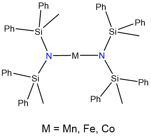
Two-coordinate complexes may also be formed through the use of bulky ligands that only allow for the binding of two to the metal center. The classic examples are given in Figure \(\sf{\PageIndex{9}}\).
Coordination Number 3
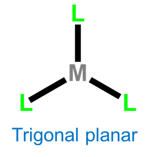
Three-coordinate complexes are similar to two-coordinate ones in that they are rare and, aside from the constraining influence of ligands, usually limited to d10 metal ions such as Cu+ , Ag+, Au+, Hg2+, and Pt(0). As expected from the Kepert model, in the absence of constraining ligands, three-coordinate complexes are trigonal planar.

Coordination Number 4
The two common four-coordinate geometries are tetrahedral and square planar.
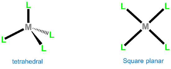
Tetrahedral complexes are commonly formed by metals possessing either a d0 or d10 electron configuration. Monometallic examples of d0 configurations include TiCl4, VO43-, WS42-, MnO4-, CrO42-, and OsO4, while d10 examples are [Ni(CO)4], [HgBr4]2-, [ZnCl4]2-, and [CdI4]2-. For other electron configurations, tetrahedral complexes are known but much less common. Examples usually involve good donor ligands and include [FeCl4]- (d5), [CoCl42-] (d6), and [NiCl4]2- (d7).
Second and third row transition metal centers with d8 electron configurations like Rh+, Ir+, Pd2+, Pt2+, and Au3+ almost exclusively exhibit square planar geometries. Beyond this, square planar geometries are often formed by Ni2+ (d8), Ni3+ (d7), and Cu2+ (d9). Examples of square planar complexes include [Cu(acac)2]; [PtCl4]2- ;Wilkinson's catalyst, [RhCl(PPh3)3]; and Vaska's complex, trans-[Ir(CO)Cl(PPh3)2].
Coordination Number 5
The two common coordination geometries for five-coordinate complexes are trigonal bipyramidal and square pyramidal.

Homoleptic [Ni(CN)5]3- possesses a square pyramidal structure, although the geometry is more common for macrocyclic complexes like the iron protoporphyrin of deoxymyoglobin shown in figure \(\sf{\PageIndex{4}}\) and for complexes containing oxo and nitrido ligands, examples of which are shown in Figure \(\sf{\PageIndex{12}}\).

In the absence of rigid constraining ligands, the relatively low energy difference between the trigonal bipyramidal and square pyramidal coordination geometries provides a mechanism for interconversion of the axial and equatorial ligands in a trigonal planar complex. For example, pentacarbonyliron(0) exhibits fluxionality involving a square pyramidal intermediate via a Berry pseudorotation mechanism, as shown in Figure \(\sf{\PageIndex{13}}\).

Coordination Number 6
The two common coordination geometries for coordination number 8 are octahedral and trigonal prismatic.

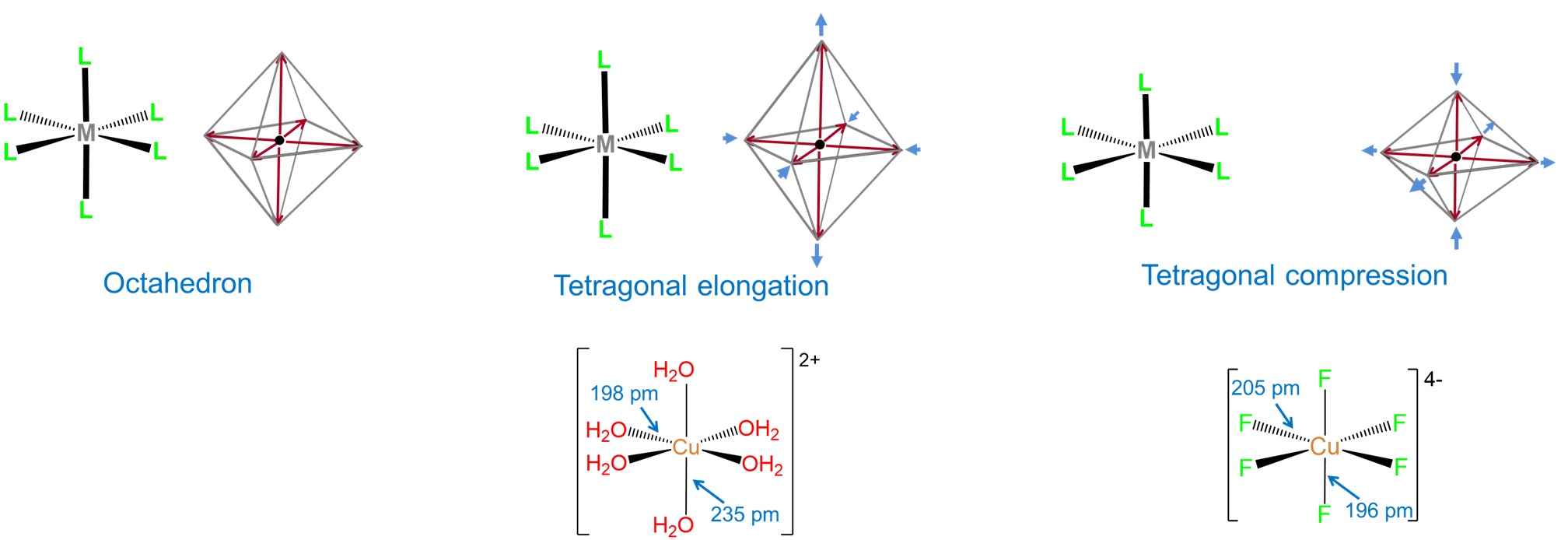
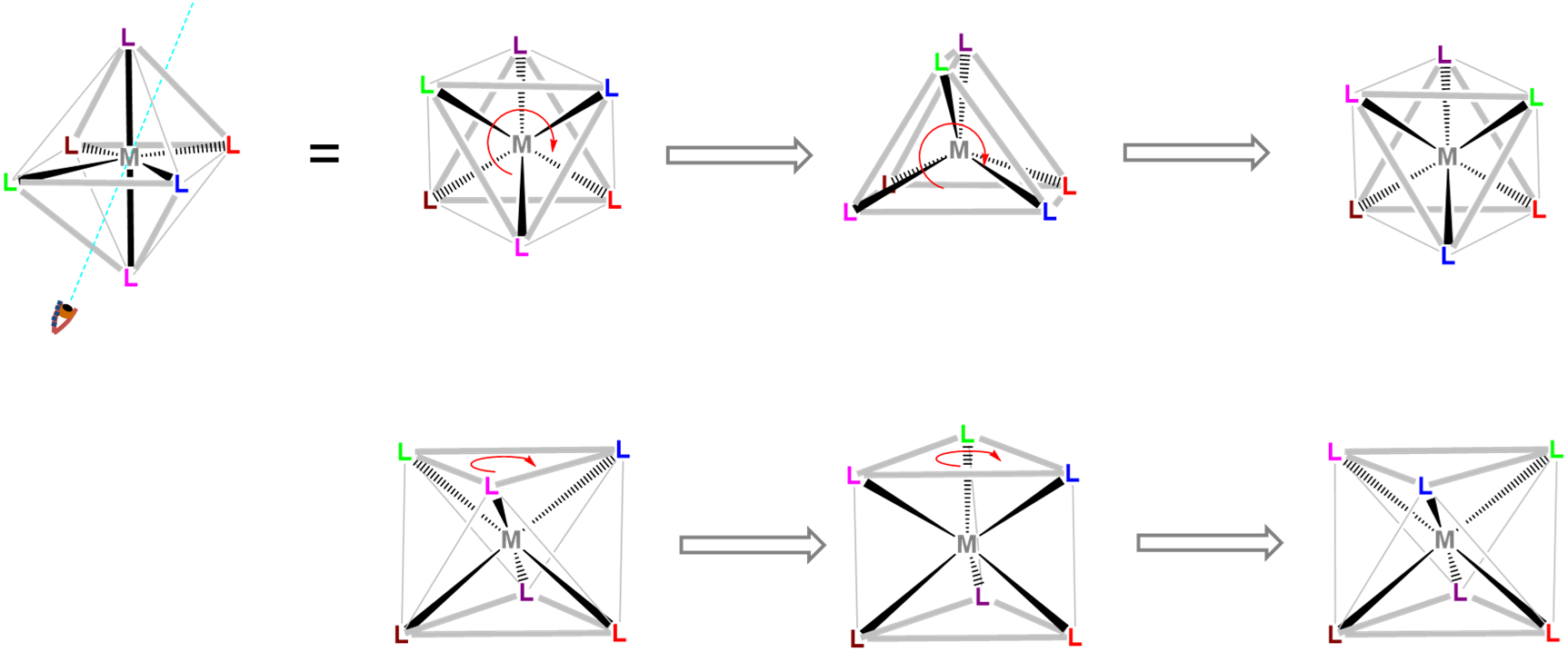
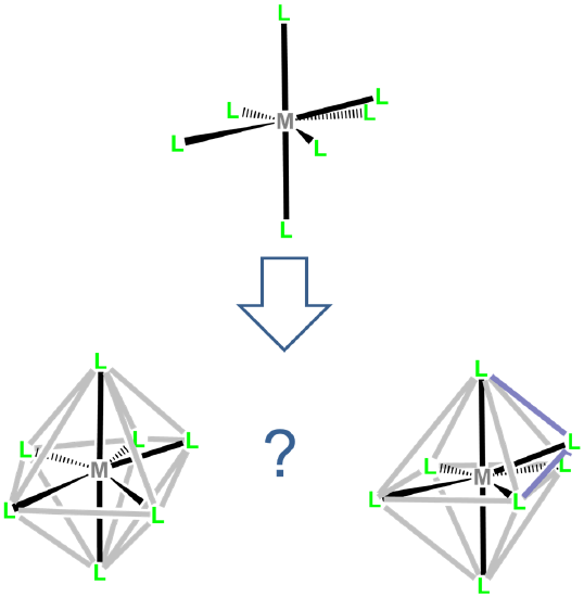
Trigonal prismatic coordination is related to octahedral coordination as shown in Figure \(\sf{\PageIndex{15}}\). As may be seen in Figure \(\sf{\PageIndex{15}}\), an octahedral coordination sphere is just a trigonal antiprism in which all edge lengths are identical. Rotation of one triangular face relative to its opposite until the two are eclipsed gives a trigonal prismatic geometry. In fact, since continuation of this rotation gives another octahedral complex, the trigonal prismatic geometry is an intermediate in isomerization reactions involving octahedral complexes.
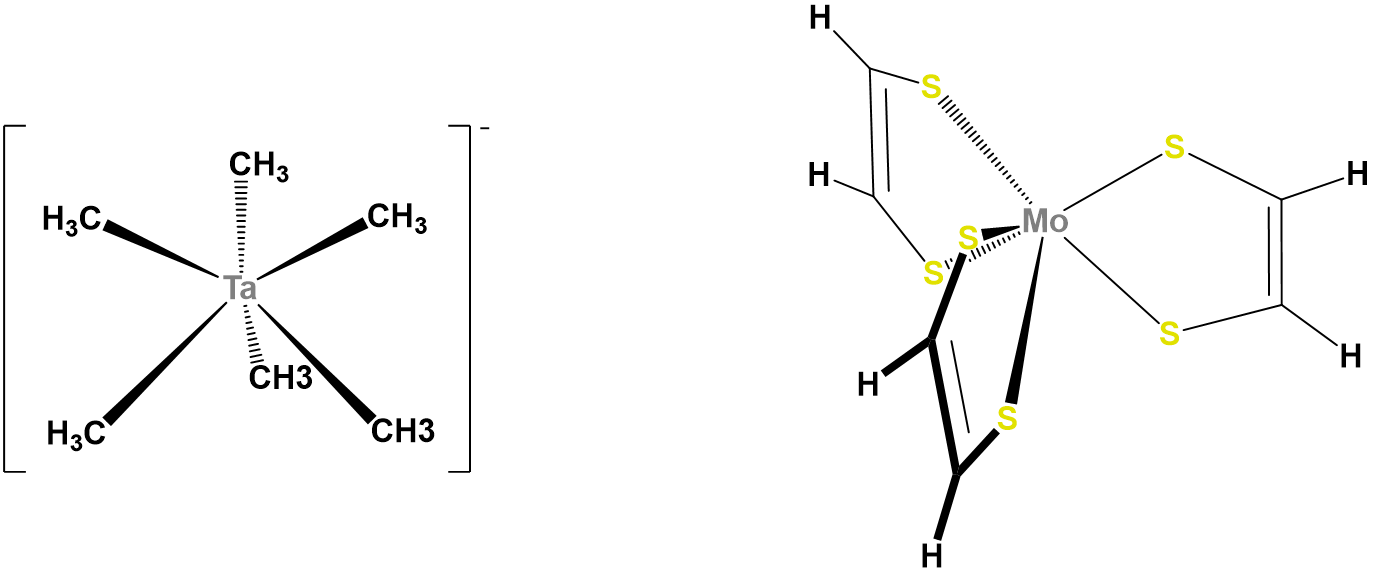
In contrast to octahedral coordination geometries, trigonal prismatic coordination (and distorted versions thereof) are rare and occur mostly for d0, d1, and d2 configurations. Examples of trigonal prismatic metal centers include the d2 Mo4+ centers in MoS2, d1 [Re(S2C2Ph2)3]-, and d0 [Ta(CH3)6]-, of which the latter two structures are given in Figure \(\sf{\PageIndex{16}}\). Semirigid ligands like that shown in Figure \(\sf{\PageIndex{4C}}\) may be used to encourage the adoption of a trigonal prismatic geometry, although once the number of d electrons present exceeds two, the preference for octahedral coordination is too great for a trigonal prismatic geometry to occur.
Coordination Number 7
Seven-coordinate complexes are rare outside of the relatively large early transition metals, lanthanides, and actinides. The three common seven-coordinate geometries are pentagonal bipyramidal, monocapped octahedral, and monocapped trigonal prismatic. The latter two are often called capped octahedral and capped trigonal prismatic, with the mono- prefix being understood.
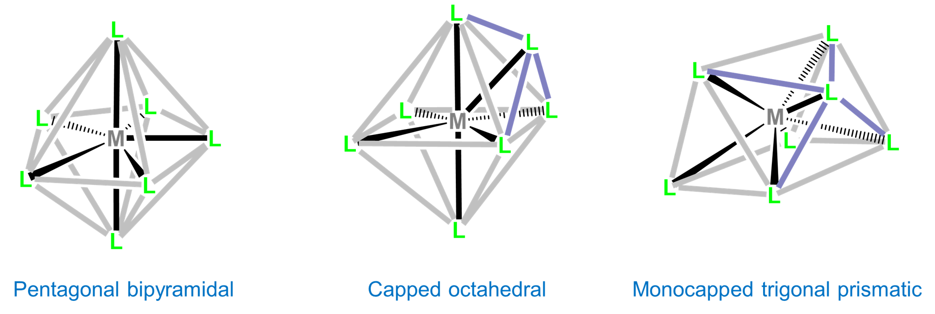
Although intraligand repulsions are smaller in the pentagonal bipyramidal coordination geometry than the capped octahedral and capped trigonal prismatic geometries, the difference is small, and the three structures are often close in energy. As a result the structure observed is often dependent on ligand-based constraints, crystal packing, and solvent effects that preference one geometry over the others.
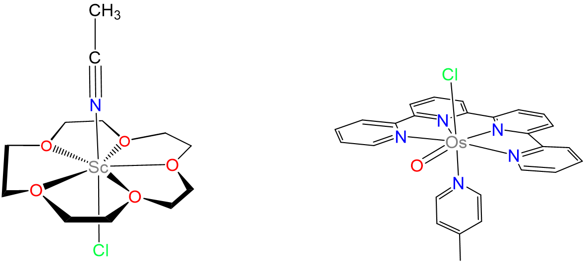
Heptacyano complexes are often pentagonal bipyramidal. Examples include [Mo(CN)7]3-, [W(CN)7]3-, and [Os(CN)7]3-. Seven-coordinate complexes containing oxo ligands commonly are pentagonal bipyramidal with the oxo ligand(s) in the less sterically hindered axial position. Examples include [NbOF6]3- and, for the inner transition metals, [UO2F5]3-. Ligands that have been used to promote formation of seven-coordinate species include 15-crown-5 and 2,2':6',2'':6'',2'''-quaterpyridine. Representative complexes are given in Figure \(\sf{\PageIndex{17}}\).
Capped trigonal prismatic geometries are common for complexes of the early transition metals. Examples include [NbF7]2- ,[TaF7]2-, and [ZrF7]3- in (NH4)3[ZrF7].
Capped octahedral geometries are found in [MoMe7]-, [WMe7]-, and [WBr3(CO)4], which contains three pairs of trans-Br and CO with the final CO capping the octahedron's (CO)3 face, as shown in Figure \(\sf{\PageIndex{18}}\).

In seven- and higher-coordinate complexes, ligand and crystal packing effects frequently give distorted coordination geometries. These geometries are intermediate between two or more of the idealized seven coordinate geometries, making it difficult to tell exactly which structure they are a distortion of (Figure \(\sf{\PageIndex{19}}\)).
Coordination Number 8
Eight-coordinate complexes are rare and occurs in discrete molecules and ions only for the relatively large early transition metals, lanthanides, and actinides. The three common eight-coordinate geometries are square antiprismatic, dodecahedral, and bicapped trigonal prismatic. In contrast, the cubic coordination geometry is only found in ionic lattices like that of CsCl and in complexes of the inner transition metals such as Na3[UF8].

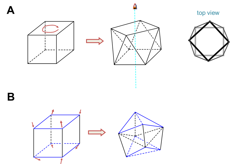
As with other high-coordinate structures, the energy difference between these eightfold coordination geometries is small enough that packing effects can significantly influence the observed structure. For example, octacyanomolybdates commonly adopt a square antiprismatic coordination geometry but depending on the counterions present can give dodecahedral or bicapped trigonal prismatic complexes. Examples are given in Figure \(\sf{\PageIndex{21}}\).

Coordination Number 9
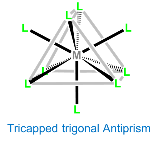
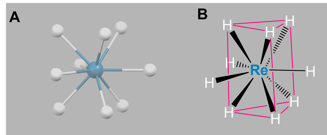
Again, nine-coordinate complexes typically require larger transition metals, lanthanides, and actinides. Coordination geometries are typically either tricapped trigonal prismatic or idiosyncratically determined by the ligands. Simple examples include the aqua complexes [Sc(H2O)9]3+, [Y(H2O)9]3+, and [La(H2O)9]3+, as well as [TcH9]2- and [ReH9]2-.
Coordination Numbers 10-16
Coordination numbers higher than nine are extremely rare for compounds that bind in \(\kappa\) fashion (form conventional metal-ligand bonds)14 and usually involve some combination of large metals, sterically undemanding ligands, and special ligand structures that promote higher coordination. Noteworthy examples include
- Twelve-coordinate [Hf(BH4)4], which illustrates how small multidentate ligands promote higher coordination numbers. As shown in Figure \(\sf{\PageIndex{23}}\), [Hf(BH4)4] has a cubooctahedral structure in which BH4- acts as a tridentate ligand, with BH3 units occupying triangular faces of the cubooctahedron to give a tetrahedron of BH4- ligands around the Hf.

- Twelve-coordinate [Ce(NO3)6]2-, in which the nitrate oxygens define an icosahedral coordination geometry as shown in Figure \(\sf{\PageIndex{24}}\). The nitrates in the structure bind the Ce center in bidentate fashion in an octahedral array.

- Fifteen-coordinate [Th(H3BNMe2BH3)4], which also uses bridging H-B-H units that occupy little of the coordination sphere. In [Th(H3BNMe2BH3)4], three of the four H3BNMe2BH3 ligands bind in \(\kappa\)4 fashion and one binds \(\kappa\)3, giving the fifteen fold coordination.16
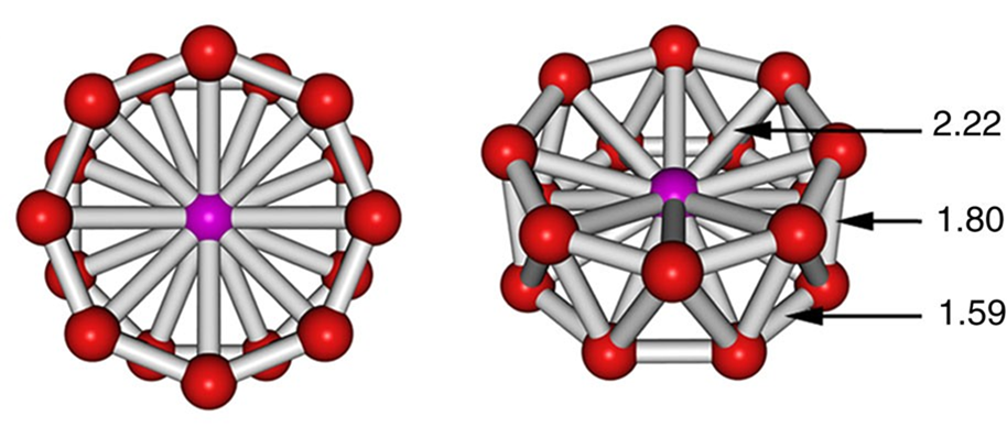
- Sixteen-coordinate [CoB16]−, which possesses the highest coordination number yet observed. Its structure is given in Figure \(\sf{\PageIndex{25}}\). The coordination geometry is an octahedral antiprism, and the complex should be considered to involve a Co center in the midst of a B16- "molecular drum" held together by cluster bonds.
References
- Dudev, M.; Wang, J.; Dudev, T.; Lim, C., Factors Governing the Metal Coordination Number in Metal Complexes from Cambridge Structural Database Analyses. The Journal of Physical Chemistry B 2006, 110(4), 1889-1895.
- Kuppuraj, G.; Dudev, M.; Lim, C., Factors Governing Metal−Ligand Distances and Coordination Geometries of Metal Complexes. The Journal of Physical Chemistry B 2009, 113 (9), 2952-2960.
- Cremades, E.; Echeverría, J.; Alvarez, S., The Trigonal Prism in Coordination Chemistry. Chemistry – A European Journal 2010, 16 (34), 10380-10396.
- Xiong, X.-G.; Wang, Y.-L.; Xu, C.-Q.; Qiu, Y.-H.; Wang, L.-S.; Li, J., On the gold–ligand covalency in linear [AuX2]− complexes. Dalton Transactions 2015, 44 (12), 5535-5546.
- Concepción Gimeno, M. The Chemistry of Gold in Laguna, Antonio (ed.) Modern Supramolecular Gold Chemistry: Gold-Metal Interactions and Applications. Wiley, 2008.
- Andersen, R. A.; Faegri, K.; Green, J. C.; Haaland, A.; Lappert, M. F.; Leung, W. P.; Rypdal, K., Synthesis of bis[bis(trimethylsilyl)amido]iron(II). Structure and bonding in M[N(SiMe3)2]2 (M = manganese, iron, cobalt): two-coordinate transition-metal amides. Inorganic Chemistry 1988, 27 (10), 1782-1786.
- Persson, I., Hydrated metal ions in aqueous solution: How regular are their structures? Pure and Applied Chemistry 2010, 82(10), 1901.
- Aramburu, J. A.; García-Fernández, P.; García-Lastra, J. M.; Moreno, M., Jahn–Teller and Non-Jahn–Teller Systems Involving CuF64– Units: Role of the Internal Electric Field in Ba2ZnF6:Cu2+ and Other Insulating Systems. The Journal of Physical Chemistry C 2017, 121(9), 5215-5224.
- Brown, M. D.; Levason, W.; Murray, D. C.; Popham, M. C.; Reid, G.; Webster, M., Primary and secondary coordination of crown ethers to scandium(iii). Synthesis, properties and structures of the reaction products of ScCl3(thf)3, ScCl3·6H2O and Sc(NO3)3·5H2O with crown ethers. Dalton Transactions 2003, (5), 857-865.
- Liu, Y.; Ng, S.-M.; Lam, W. W. Y.; Yiu, S.-M.; Lau, T.-C., A Highly Reactive Seven-Coordinate Osmium(V) Oxo Complex: [OsV(O)(qpy)(pic)Cl]2+. Angewandte Chemie International Edition 2016, 55 (1), 288-291.
- Popov, I., Jian, T., Lopez, G. et al. Cobalt-centred boron molecular drums with the highest coordination number in the CoB16− cluster. Nat Commun 6, 8654 (2015). https://doi.org/10.1038/ncomms9654
- The structures are rendered from cif data reported in the following publications: (A) square antiprismatic [Mo(CN)8]3-: Wen-Yan Liu, Hu Zhou, Ai-Hua Yuan, Acta Crystallographica Section E: Structure Reports Online, 2008, 64, m1151, (B) dodecahedral [Mo(CN)8]4-: B.J.Corden, J.A.Cunningham, R.Eisenberg, Inorganic Chemistry, 1970, 9, 356.
- The structure of ReH92- is rendered from the structure reported in Abrahams, S.C.; Ginsberg, A.P.; Knox, K. Transition metal-hydrogen compounds. II. The crystal and molecular structure of potassium rhenium hydride, K2ReH9 Inorganic Chemistry, 1964, 3, 558-567.
- There are other complexes in which a metal may be said to interact with more than sixteen "ligand atoms", but these are not usually considered to possess a higher coordination number. For example, in some \(\pi\) complexes like \(\eta\)5-Cp4U, technically there are 20 C atoms fastened to the U, but these complexes are better considered as 12-coordinate than twenty (since each cyclopentadienyl ring is isolobal with a fac-coordinated set of 3 L ligands), while the metal centers in endohedral fullerene species like La@C60 do not interact with all sixty carbon atoms at once, and so are better thought of as a metal trapped in a spacious sixty-carbon cage.
- Zalkin, A.; Forrester, J.D.; Templeton, D.H. Crystal structure of cerium magnesium nitrate hydrate Journal of Chemical Physics, 1963, 39, 2881-2891.
- Daly, S. R.; Piccoli, P. M. B.; Schultz, A. J.; Todorova, T. K.; Gagliardi, L.; Girolami, G. S., Synthesis and Properties of a Fifteen-Coordinate Complex: The Thorium Aminodiboranate [Th(H3BNMe2BH3)4]. Angewandte Chemie International Edition 2010, 49 (19), 3379-3381.
- Popov, I., Jian, T., Lopez, G., Boldyrev, A. I.; Wang, L-S. Cobalt-centred boron molecular drums with the highest coordination number in the CoB16− cluster. Nat Commun 6, 8654 (2015).

