B.1 Ligand Field Theory
- Page ID
- 60622
\( \newcommand{\vecs}[1]{\overset { \scriptstyle \rightharpoonup} {\mathbf{#1}} } \)
\( \newcommand{\vecd}[1]{\overset{-\!-\!\rightharpoonup}{\vphantom{a}\smash {#1}}} \)
\( \newcommand{\id}{\mathrm{id}}\) \( \newcommand{\Span}{\mathrm{span}}\)
( \newcommand{\kernel}{\mathrm{null}\,}\) \( \newcommand{\range}{\mathrm{range}\,}\)
\( \newcommand{\RealPart}{\mathrm{Re}}\) \( \newcommand{\ImaginaryPart}{\mathrm{Im}}\)
\( \newcommand{\Argument}{\mathrm{Arg}}\) \( \newcommand{\norm}[1]{\| #1 \|}\)
\( \newcommand{\inner}[2]{\langle #1, #2 \rangle}\)
\( \newcommand{\Span}{\mathrm{span}}\)
\( \newcommand{\id}{\mathrm{id}}\)
\( \newcommand{\Span}{\mathrm{span}}\)
\( \newcommand{\kernel}{\mathrm{null}\,}\)
\( \newcommand{\range}{\mathrm{range}\,}\)
\( \newcommand{\RealPart}{\mathrm{Re}}\)
\( \newcommand{\ImaginaryPart}{\mathrm{Im}}\)
\( \newcommand{\Argument}{\mathrm{Arg}}\)
\( \newcommand{\norm}[1]{\| #1 \|}\)
\( \newcommand{\inner}[2]{\langle #1, #2 \rangle}\)
\( \newcommand{\Span}{\mathrm{span}}\) \( \newcommand{\AA}{\unicode[.8,0]{x212B}}\)
\( \newcommand{\vectorA}[1]{\vec{#1}} % arrow\)
\( \newcommand{\vectorAt}[1]{\vec{\text{#1}}} % arrow\)
\( \newcommand{\vectorB}[1]{\overset { \scriptstyle \rightharpoonup} {\mathbf{#1}} } \)
\( \newcommand{\vectorC}[1]{\textbf{#1}} \)
\( \newcommand{\vectorD}[1]{\overrightarrow{#1}} \)
\( \newcommand{\vectorDt}[1]{\overrightarrow{\text{#1}}} \)
\( \newcommand{\vectE}[1]{\overset{-\!-\!\rightharpoonup}{\vphantom{a}\smash{\mathbf {#1}}}} \)
\( \newcommand{\vecs}[1]{\overset { \scriptstyle \rightharpoonup} {\mathbf{#1}} } \)
\( \newcommand{\vecd}[1]{\overset{-\!-\!\rightharpoonup}{\vphantom{a}\smash {#1}}} \)
\(\newcommand{\avec}{\mathbf a}\) \(\newcommand{\bvec}{\mathbf b}\) \(\newcommand{\cvec}{\mathbf c}\) \(\newcommand{\dvec}{\mathbf d}\) \(\newcommand{\dtil}{\widetilde{\mathbf d}}\) \(\newcommand{\evec}{\mathbf e}\) \(\newcommand{\fvec}{\mathbf f}\) \(\newcommand{\nvec}{\mathbf n}\) \(\newcommand{\pvec}{\mathbf p}\) \(\newcommand{\qvec}{\mathbf q}\) \(\newcommand{\svec}{\mathbf s}\) \(\newcommand{\tvec}{\mathbf t}\) \(\newcommand{\uvec}{\mathbf u}\) \(\newcommand{\vvec}{\mathbf v}\) \(\newcommand{\wvec}{\mathbf w}\) \(\newcommand{\xvec}{\mathbf x}\) \(\newcommand{\yvec}{\mathbf y}\) \(\newcommand{\zvec}{\mathbf z}\) \(\newcommand{\rvec}{\mathbf r}\) \(\newcommand{\mvec}{\mathbf m}\) \(\newcommand{\zerovec}{\mathbf 0}\) \(\newcommand{\onevec}{\mathbf 1}\) \(\newcommand{\real}{\mathbb R}\) \(\newcommand{\twovec}[2]{\left[\begin{array}{r}#1 \\ #2 \end{array}\right]}\) \(\newcommand{\ctwovec}[2]{\left[\begin{array}{c}#1 \\ #2 \end{array}\right]}\) \(\newcommand{\threevec}[3]{\left[\begin{array}{r}#1 \\ #2 \\ #3 \end{array}\right]}\) \(\newcommand{\cthreevec}[3]{\left[\begin{array}{c}#1 \\ #2 \\ #3 \end{array}\right]}\) \(\newcommand{\fourvec}[4]{\left[\begin{array}{r}#1 \\ #2 \\ #3 \\ #4 \end{array}\right]}\) \(\newcommand{\cfourvec}[4]{\left[\begin{array}{c}#1 \\ #2 \\ #3 \\ #4 \end{array}\right]}\) \(\newcommand{\fivevec}[5]{\left[\begin{array}{r}#1 \\ #2 \\ #3 \\ #4 \\ #5 \\ \end{array}\right]}\) \(\newcommand{\cfivevec}[5]{\left[\begin{array}{c}#1 \\ #2 \\ #3 \\ #4 \\ #5 \\ \end{array}\right]}\) \(\newcommand{\mattwo}[4]{\left[\begin{array}{rr}#1 \amp #2 \\ #3 \amp #4 \\ \end{array}\right]}\) \(\newcommand{\laspan}[1]{\text{Span}\{#1\}}\) \(\newcommand{\bcal}{\cal B}\) \(\newcommand{\ccal}{\cal C}\) \(\newcommand{\scal}{\cal S}\) \(\newcommand{\wcal}{\cal W}\) \(\newcommand{\ecal}{\cal E}\) \(\newcommand{\coords}[2]{\left\{#1\right\}_{#2}}\) \(\newcommand{\gray}[1]{\color{gray}{#1}}\) \(\newcommand{\lgray}[1]{\color{lightgray}{#1}}\) \(\newcommand{\rank}{\operatorname{rank}}\) \(\newcommand{\row}{\text{Row}}\) \(\newcommand{\col}{\text{Col}}\) \(\renewcommand{\row}{\text{Row}}\) \(\newcommand{\nul}{\text{Nul}}\) \(\newcommand{\var}{\text{Var}}\) \(\newcommand{\corr}{\text{corr}}\) \(\newcommand{\len}[1]{\left|#1\right|}\) \(\newcommand{\bbar}{\overline{\bvec}}\) \(\newcommand{\bhat}{\widehat{\bvec}}\) \(\newcommand{\bperp}{\bvec^\perp}\) \(\newcommand{\xhat}{\widehat{\xvec}}\) \(\newcommand{\vhat}{\widehat{\vvec}}\) \(\newcommand{\uhat}{\widehat{\uvec}}\) \(\newcommand{\what}{\widehat{\wvec}}\) \(\newcommand{\Sighat}{\widehat{\Sigma}}\) \(\newcommand{\lt}{<}\) \(\newcommand{\gt}{>}\) \(\newcommand{\amp}{&}\) \(\definecolor{fillinmathshade}{gray}{0.9}\)Concepts from molecular orbital theory are useful in understanding the reactivity of coordination compounds. One of the basic ways of applying MO concepts to coordination chemistry is in Ligand Field Theory. Ligand field theory looks at the effect of donor atoms on the energy of d orbitals in the metal complex.
There are two ways in which we sometimes think about the effect of ligands on the d electrons on a metal. On the basis of simple electron-electron repulsion, donation of a lone pair might raise an occupied d orbital in energy. Alternatively, we can think about bonding interactions between ligand orbitals and d orbitals. This second way of thinking about things is a little bit more useful, and that's the approach we'll focus on, here.
Either way, there are interactions between ligand electrons and d electrons, that usually end up raising the d electrons in energy. The effect depends on the coordination geometry geometry of the ligands. Ligands in a tetrahedral coordination sphere will have a different effect than ligands in an octahedral coordination sphere, because they will interact with the different d orbitals in different ways.
- Ligand field theory looks at the effect of donor atoms on the energy of d orbitals in the metal complex.
- The effect depends on the coordination geometry geometry of the ligands.
Octahedral case
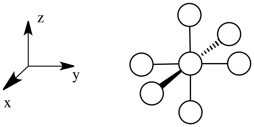
Suppose a complex has an octahedral coordination sphere. Assume the six ligands all lie along the x, y and z axes.
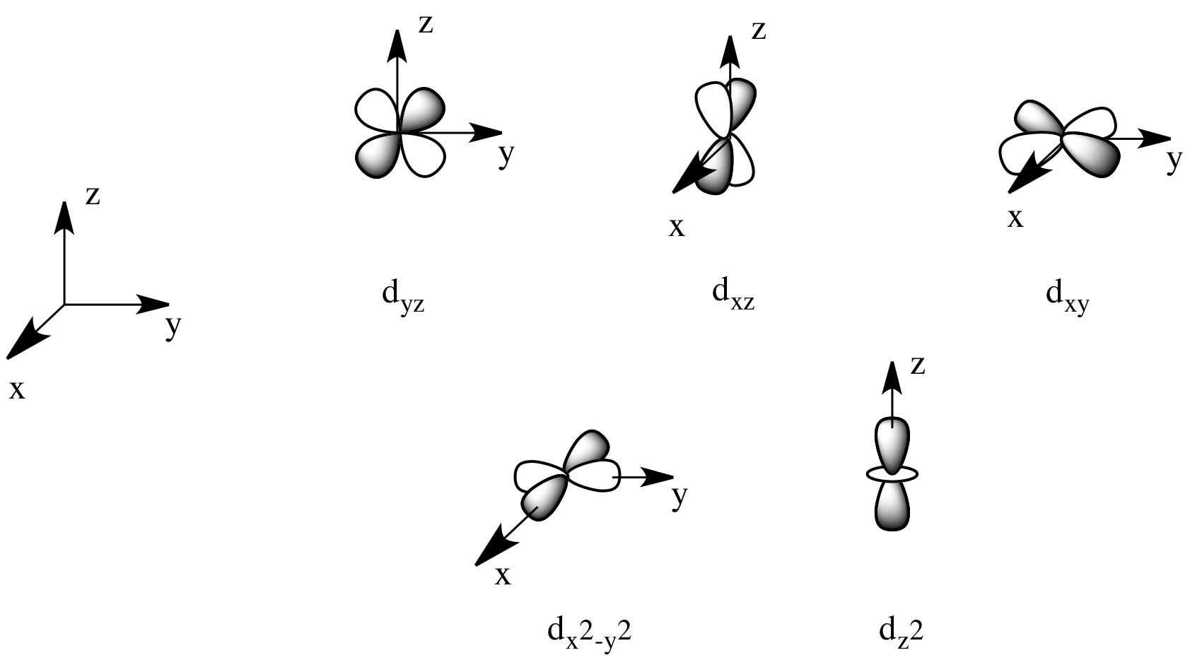
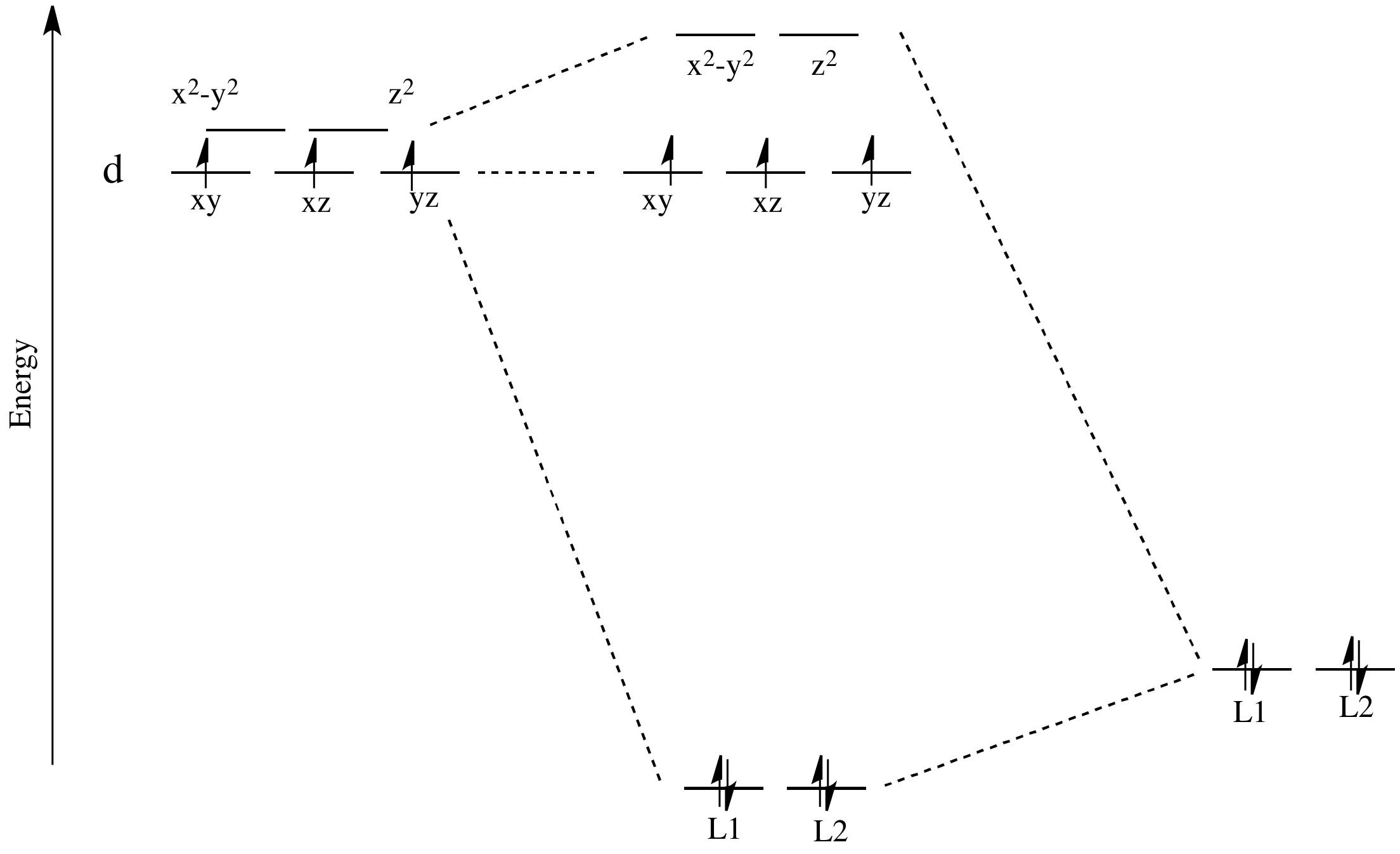
There are two d orbitals that will interact very strongly with these ligands: the dx2-y2, which lies directly on the x and y axes, and the dz2, which lies directly on the z axis. Together, these two metal orbitals and the ligand orbitals that interact with them will form new bonding and antibonding orbitals.
The drawing below is simplified. The ligands will also interact with s and p orbitals, but because those level have no electrons in them, we're not going to worry about them. We also won't worry about interactions from the other four ligands with the d orbitals (possible by symmetry considerations, but also a more complicated picture).
Now, remember that metals usually have d electrons that are much higher in energy than those on typical donor atoms (like oxygen, sulfur, nitrogen or phosphorus). That means the antibonding combinations will be much closer in energy to the original d orbitals, because both are relatively high in energy. The bonding combination will be much closer in energy to the original ligand orbitals, because these ones are all relatively low in energy.
That energetic similarity generally translates into a similarity in shape and location as well. In other words, the antibonding combination between a d orbital and a ligand orbital is a lot like the original d orbital. The bonding combination is more like the original ligand orbital than the original d orbital. Because of those similarities, inorganic chemists often refer to those antibonding orbitals as if they were still the original d orbitals.
These two orbitals will be raised relatively high in energy by sigma bonding interactions with the donor orbitals. If there are electrons in the picture, it might look something like this:
- Assume the six ligands all lie along the x, y and z axes.
- The dx2-y2 and the dz2 orbitals lie along the bond axes.
- These two orbitals will be raised relatively high in energy.
- These orbitals are like antibonding levels.
- These orbitals are sometimes called the "eg" set of orbitals. The term "eg" comes from the mathematics of symmetry.
On the other hand, the other three d orbitals, the dxy, dxz and dyz, all lie between the donor ligands, rather than hitting them head-on. These orbitals will interact less strongly with the donor electrons.
- The dxy, dxz and dyz orbitals all lie between the bond axes.
- These three orbitals will be changed in energy only a little.
- These orbitals are more like non-bonding orbitals.
- These orbitals are sometimes called the "t2g" set of orbitals.
Remember, only the energy of the electrons affects the overall energy of the system. The unoccupied d orbitals are raised in energy, but the occupied orbitals go down in energy (or else stay the same).
Apart from the stabilization of the complex, there is another consequence of this picture. What we are left with is two distinct sets of d energy levels, one lower than the other. That will have an effect on the electron configuration at the metal atom in the complex. That means there will be cases where electrons could be paired or unpaired, depending on how these orbitals are occupied.
Take the case of the biologically important iron(II) ion. It has a d6 valence electron configuration. In less formal parlance of inorganic chemistry, "iron(II) is d6". In an iron(II) ion all alone in space, all the d orbitals would have the same energy level. We would put one electron in each orbital, and have one left. It would need to pair up in one of the d orbitals. (Notice that, in the chemistry of transition metal ions, the valence s and p orbitals are always assumed to be unoccupied).
Things are very different in an octahedral complex, like K4[Fe(CN)6]. In that case, the d orbitals are no longer at the same energy level. There are two possible configurations to consider.
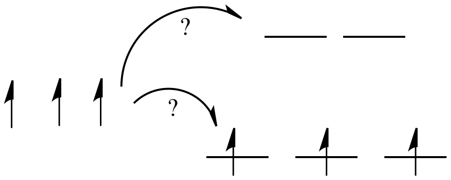
In one case, one electron would go into each of the lower energy d orbitals. A choice would be made for the fourth electron. Does it go into the higher energy d orbital, or does it pair up with one of the lower energy d electrons? The choice depends on how much higher in energy the upper d orbitals are, compared to how much energy it costs to put two electrons in the same d orbital.
If the "d orbital splitting energy" is pretty low, so that the two sets of d orbitals are still pretty similar in energy, the next electron can go into a higher orbital. Pairing would not be required until the final electron. Overall, that would leave four unpaired electrons, just like in the case of a lone metal ion in space. This is called the "high-spin" case, because electrons can easily go into the higher orbital.
If the d orbital splitting energy is too high, the next electron must pair up in a lower orbital. All three remaining electrons pair up, and so there are no unpaired electrons in the complex. This is called the "low-spin" case, because electrons more easily pair up in the orbital.
- The electron configuration can be "high spin" or "low-spin", depending on how large the energy splitting is between the two sets of d orbitals.
The difference between the high-spin case and the low-spin case is significant, because unpaired electrons affect the magnetic properties of a material. The low-spin case would be diamagnetic, resulting in no interaction with a magnetic field. However, the high-spin case would be paramagnetic, and would be attracted to a magnetic field.
It turns out K4[Fe(CN)6] is diamagnetic, thus, it is pretty clear that it is a low-spin complex. The energy difference between the two d orbital levels is relatively large in this case. In addition to influencing magnetic properties, whether a complex is high- or low-spin also influences reactivity. Compounds with high-energy d electrons are generally more labile, meaning they let go of ligands more easily.
- electron configuration influences magnetic properties
- electron configuration influences lability (how easily ligands are released)
Reasons for Low-spin vs. High-spin
There are a few factors that determine the magnitude of the d orbital splitting, and whether an electron can occupy the higher energy set of orbitals, rather than pairing up. It is based partly on ligand field strength, which is explored on the next page. It also depends on the charge on the metal ion, and whether the metal is in the first, second or third row of the transition metals.
Metals in the second and third row of the periodic table almost never form high-spin complexes. The d orbital energy splitting in these cases is larger than for first row metals. In addition, the pairing energy is lower because the orbitals are larger. As a result, electrons are much more likely to pair up than to occupy the next energy level.
High-spin versus low-spin cases involve a trade-off between the d orbital splitting energy and the pairing energy.
The reason for these differences between first row and heavier transition metals is sometimes ascribed to the very diffuse d orbitals in the latter cases. In these larger orbitals, electrons are more spread out, and so double occupation of one energy level is less problematic. It is also sometimes said that second and third row d orbitals overlap more strongly with ligand orbitals. Consequently stronger interactions result, leading to larger d orbital splittings.
It is significant that most important transition metal ions in biology are from the first row of the transition block and are pretty labile. That fact plays an important role in the ease of formation and deconstruction of transition-metal containing proteins. In terms of formation, if the metal is more easily released by its previous ligands (either water or some compound that delivers the metal to the site of enzyme construction), it can form the necessary enzyme more quickly. However, even if a metal-containing enzyme plays a useful role, it should not be too stable, because we need to be able to regulate the level of enzyme concentration for optimum activity, or remove enzyme if it becomes damaged. Thus, it is important that the metal ion can be removed easily.
Problem CC8.1.
Draw both high spin and low spin d-orbital splitting diagrams for the following ions in an octahedral environment and determine the number of unpaired electrons in each case.
a) Mn2+ b) Co2+ c) Ni2+ d) Cu+ e) Fe3+ f) Cr2+ g) Zn2+
Problem CC8.2.
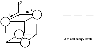
The d orbital splitting diagram for a tetrahedral coordination environment is shown below. Given this diagram, and the axes in the accompanying picture, identify which d orbitals are found at which level. In the picture, the metal atom is at the centre of the cube, and the circle represent the ligands.
Problem CC8.3.
Typically, the d orbital splitting energy in the tetrahedral case is only about 4/9 as large as the splitting energy in the analogous octahedral case. Explain why it is smaller for the tetrahedral case.
Problem CC8.4.
Suppose each of the ions in Problem CC8.1. were in tetrahedral, rather than octahedral, coordimnation environments. Draw the d orbital diagrams for the high spin and the low spin case for each ion.
Problem CC8.5.
Usually, tetrahedral ions are high spin rather than low spin. Explain why.
Problem CC8.6.
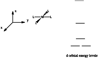
The d orbital splitting diagram for a square planar environment is shown below. Given this diagram, and the axes in the accompanying picture, identify which d orbitals are found at which level.


