
6.2.2: The Law of Reflection
- Page ID
- 220528

\( \newcommand{\vecs}[1]{\overset { \scriptstyle \rightharpoonup} {\mathbf{#1}} } \)
\( \newcommand{\vecd}[1]{\overset{-\!-\!\rightharpoonup}{\vphantom{a}\smash {#1}}} \)
\( \newcommand{\id}{\mathrm{id}}\) \( \newcommand{\Span}{\mathrm{span}}\)
( \newcommand{\kernel}{\mathrm{null}\,}\) \( \newcommand{\range}{\mathrm{range}\,}\)
\( \newcommand{\RealPart}{\mathrm{Re}}\) \( \newcommand{\ImaginaryPart}{\mathrm{Im}}\)
\( \newcommand{\Argument}{\mathrm{Arg}}\) \( \newcommand{\norm}[1]{\| #1 \|}\)
\( \newcommand{\inner}[2]{\langle #1, #2 \rangle}\)
\( \newcommand{\Span}{\mathrm{span}}\)
\( \newcommand{\id}{\mathrm{id}}\)
\( \newcommand{\Span}{\mathrm{span}}\)
\( \newcommand{\kernel}{\mathrm{null}\,}\)
\( \newcommand{\range}{\mathrm{range}\,}\)
\( \newcommand{\RealPart}{\mathrm{Re}}\)
\( \newcommand{\ImaginaryPart}{\mathrm{Im}}\)
\( \newcommand{\Argument}{\mathrm{Arg}}\)
\( \newcommand{\norm}[1]{\| #1 \|}\)
\( \newcommand{\inner}[2]{\langle #1, #2 \rangle}\)
\( \newcommand{\Span}{\mathrm{span}}\) \( \newcommand{\AA}{\unicode[.8,0]{x212B}}\)
\( \newcommand{\vectorA}[1]{\vec{#1}} % arrow\)
\( \newcommand{\vectorAt}[1]{\vec{\text{#1}}} % arrow\)
\( \newcommand{\vectorB}[1]{\overset { \scriptstyle \rightharpoonup} {\mathbf{#1}} } \)
\( \newcommand{\vectorC}[1]{\textbf{#1}} \)
\( \newcommand{\vectorD}[1]{\overrightarrow{#1}} \)
\( \newcommand{\vectorDt}[1]{\overrightarrow{\text{#1}}} \)
\( \newcommand{\vectE}[1]{\overset{-\!-\!\rightharpoonup}{\vphantom{a}\smash{\mathbf {#1}}}} \)
\( \newcommand{\vecs}[1]{\overset { \scriptstyle \rightharpoonup} {\mathbf{#1}} } \)
\( \newcommand{\vecd}[1]{\overset{-\!-\!\rightharpoonup}{\vphantom{a}\smash {#1}}} \)
\(\newcommand{\avec}{\mathbf a}\) \(\newcommand{\bvec}{\mathbf b}\) \(\newcommand{\cvec}{\mathbf c}\) \(\newcommand{\dvec}{\mathbf d}\) \(\newcommand{\dtil}{\widetilde{\mathbf d}}\) \(\newcommand{\evec}{\mathbf e}\) \(\newcommand{\fvec}{\mathbf f}\) \(\newcommand{\nvec}{\mathbf n}\) \(\newcommand{\pvec}{\mathbf p}\) \(\newcommand{\qvec}{\mathbf q}\) \(\newcommand{\svec}{\mathbf s}\) \(\newcommand{\tvec}{\mathbf t}\) \(\newcommand{\uvec}{\mathbf u}\) \(\newcommand{\vvec}{\mathbf v}\) \(\newcommand{\wvec}{\mathbf w}\) \(\newcommand{\xvec}{\mathbf x}\) \(\newcommand{\yvec}{\mathbf y}\) \(\newcommand{\zvec}{\mathbf z}\) \(\newcommand{\rvec}{\mathbf r}\) \(\newcommand{\mvec}{\mathbf m}\) \(\newcommand{\zerovec}{\mathbf 0}\) \(\newcommand{\onevec}{\mathbf 1}\) \(\newcommand{\real}{\mathbb R}\) \(\newcommand{\twovec}[2]{\left[\begin{array}{r}#1 \\ #2 \end{array}\right]}\) \(\newcommand{\ctwovec}[2]{\left[\begin{array}{c}#1 \\ #2 \end{array}\right]}\) \(\newcommand{\threevec}[3]{\left[\begin{array}{r}#1 \\ #2 \\ #3 \end{array}\right]}\) \(\newcommand{\cthreevec}[3]{\left[\begin{array}{c}#1 \\ #2 \\ #3 \end{array}\right]}\) \(\newcommand{\fourvec}[4]{\left[\begin{array}{r}#1 \\ #2 \\ #3 \\ #4 \end{array}\right]}\) \(\newcommand{\cfourvec}[4]{\left[\begin{array}{c}#1 \\ #2 \\ #3 \\ #4 \end{array}\right]}\) \(\newcommand{\fivevec}[5]{\left[\begin{array}{r}#1 \\ #2 \\ #3 \\ #4 \\ #5 \\ \end{array}\right]}\) \(\newcommand{\cfivevec}[5]{\left[\begin{array}{c}#1 \\ #2 \\ #3 \\ #4 \\ #5 \\ \end{array}\right]}\) \(\newcommand{\mattwo}[4]{\left[\begin{array}{rr}#1 \amp #2 \\ #3 \amp #4 \\ \end{array}\right]}\) \(\newcommand{\laspan}[1]{\text{Span}\{#1\}}\) \(\newcommand{\bcal}{\cal B}\) \(\newcommand{\ccal}{\cal C}\) \(\newcommand{\scal}{\cal S}\) \(\newcommand{\wcal}{\cal W}\) \(\newcommand{\ecal}{\cal E}\) \(\newcommand{\coords}[2]{\left\{#1\right\}_{#2}}\) \(\newcommand{\gray}[1]{\color{gray}{#1}}\) \(\newcommand{\lgray}[1]{\color{lightgray}{#1}}\) \(\newcommand{\rank}{\operatorname{rank}}\) \(\newcommand{\row}{\text{Row}}\) \(\newcommand{\col}{\text{Col}}\) \(\renewcommand{\row}{\text{Row}}\) \(\newcommand{\nul}{\text{Nul}}\) \(\newcommand{\var}{\text{Var}}\) \(\newcommand{\corr}{\text{corr}}\) \(\newcommand{\len}[1]{\left|#1\right|}\) \(\newcommand{\bbar}{\overline{\bvec}}\) \(\newcommand{\bhat}{\widehat{\bvec}}\) \(\newcommand{\bperp}{\bvec^\perp}\) \(\newcommand{\xhat}{\widehat{\xvec}}\) \(\newcommand{\vhat}{\widehat{\vvec}}\) \(\newcommand{\uhat}{\widehat{\uvec}}\) \(\newcommand{\what}{\widehat{\wvec}}\) \(\newcommand{\Sighat}{\widehat{\Sigma}}\) \(\newcommand{\lt}{<}\) \(\newcommand{\gt}{>}\) \(\newcommand{\amp}{&}\) \(\definecolor{fillinmathshade}{gray}{0.9}\)Learning Objectives
By the end of this section, you will be able to:
- Explain the reflection of light from polished and rough surfaces
- Describe the reflection of the interface between two transparent media
Whenever we look into a mirror, or squint at sunlight glinting from a lake, we are seeing a reflection. When you look at a piece of white paper, you are seeing light scattered from it. Large telescopes use reflection to form an image of stars and other astronomical objects.
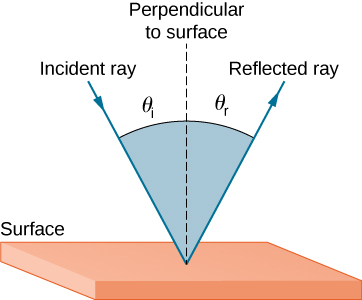
The law of reflection states that the angle of reflection equals the angle of incidence:
\[θ_r=θ_i \label{law of reflection}\]
The law of reflection is illustrated in Figure \(\PageIndex{1}\), which also shows how the angle of incidence and angle of reflection are measured relative to the perpendicular to the surface at the point where the light ray strikes.
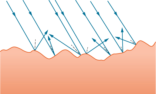
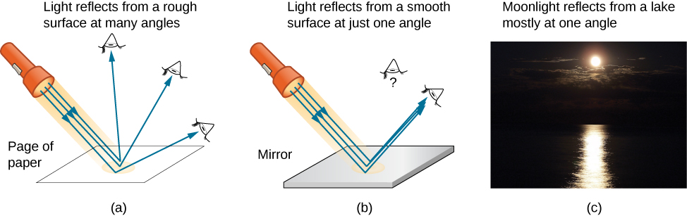
We expect to see reflections from smooth surfaces, but Figure \(\PageIndex{2}\) illustrates how a rough surface reflects light. Since the light strikes different parts of the surface at different angles, it is reflected in many different directions, or diffused. Diffused light is what allows us to see a sheet of paper from any angle, as shown in Figure \(\PageIndex{1a}\).
People, clothing, leaves, and walls all have rough surfaces and can be seen from all sides. A mirror, on the other hand, has a smooth surface (compared with the wavelength of light) and reflects light at specific angles, as illustrated in Figure \(\PageIndex{3b}\). When the Moon reflects from a lake, as shown in Figure \(\PageIndex{1c}\), a combination of these effects takes place.
Reflection from the interface between two transmissive materials
Figure \(\PageIndex{4}\):illustrates what happens when electromagnetic radiation crosses a smooth interface into a dielectric medium that has a higher refractive index (\(\eta_{t}\) > \(\eta_{i}\)). We see two phenomena: reflection and refraction (a specific type of transmission). The angle of reflection, θr, equals the angle of incidence, θi, where each is defined with respect to the surface normal. The angle of refraction, θt, (t for transmitted) is described by Snell’s law (of Refraction) which is described in the next section.
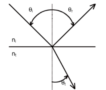
Figure \(\PageIndex{4}\): Reflection and refraction at the interface between two transmissive materials of differing refractive indices.
The radiant power of the reflected and refracted light depend on several factors. The Fresnel equations describe the dependence of the reflected light on the angle of incidence, the refractive indices of the two media and, in some cases, the polarization of the incident beam. In the case of normal incidence, the fraction of light reflected reflectance (ρ=Ir/I0) is
\(\rho=\left[\frac{n_{i}-n_{i}}{n_{i}+n_{i}}\right]^{2}\)
where Ir is the intensity of light reflected and I0 is the incident intensity. The reflectance is thus related to the difference in refractive indices between the two media. For glass and air, which have refractive indices of 1.50 and 1.00, respectively, the fraction of reflected light is 0.04. For water and diamond, which has a refractive index of 2.4, the fraction of light reflected is 0.08. It is therefore easier to see diamonds in water than it is to see glass in air.
It should be noted that reflection occurs upon each pass through an interface. Consequently for light passing through a cuvette reflection will occur at 4 interfaces and the fraction of light lost due to reflection will (ρ)4.
An of interesting tangent that is important for the ATR accessory with our FTIR
Snell's law, \(\eta_{i} \sin \theta_{i}=\eta_{t} \sin \theta_{t}\), predicts the phenomenon of total internal reflection, depicted in Figure \(\PageIndex{5}\). Whenever light is traveling from a more optically dense medium to a less optically dense medium \(\eta_{i}\) > \(\eta_{t}\), θt can appear to exceed 90. In reality, most of the incident beam is totally internally reflected. At incident angles above a critical angle specified by Eqn. 4.1, the transmitted beam becomes vanishingly small and propagates parallel to the interface. This small electric field extends beyond the boundary of the interface into the lower refractive index medium for a distance approximately equal to the wavelength of light. This electric field beyond the interface is called the evanescent field, and it can be used to excite molecules on the other side (\(\eta_{t}\)) of the interface, provided they are within a distance on the order of the wavelength of light. The evanescent field strength is dependent upon the polarization (the orientation of the electric field), the angle of the incident beam and the refractive indices of the two media. The technique of “attenuated total internal reflectance”, or ATR, is commonly used in infrared spectroscopy to make measurements of films or solids by launching an IR evanescent wave into a thin layer of the material of interest adsorbed or clamped to a crystal in which an IR beam undergoes multiple internal reflections.
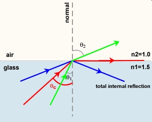
Figure \(\PageIndex{5}\): Total internal reflection for light traveling from glass to air.