
5.2: Lattice Structures in Metallic Solids
- Page ID
- 444149
\( \newcommand{\vecs}[1]{\overset { \scriptstyle \rightharpoonup} {\mathbf{#1}} } \)
\( \newcommand{\vecd}[1]{\overset{-\!-\!\rightharpoonup}{\vphantom{a}\smash {#1}}} \)
\( \newcommand{\dsum}{\displaystyle\sum\limits} \)
\( \newcommand{\dint}{\displaystyle\int\limits} \)
\( \newcommand{\dlim}{\displaystyle\lim\limits} \)
\( \newcommand{\id}{\mathrm{id}}\) \( \newcommand{\Span}{\mathrm{span}}\)
( \newcommand{\kernel}{\mathrm{null}\,}\) \( \newcommand{\range}{\mathrm{range}\,}\)
\( \newcommand{\RealPart}{\mathrm{Re}}\) \( \newcommand{\ImaginaryPart}{\mathrm{Im}}\)
\( \newcommand{\Argument}{\mathrm{Arg}}\) \( \newcommand{\norm}[1]{\| #1 \|}\)
\( \newcommand{\inner}[2]{\langle #1, #2 \rangle}\)
\( \newcommand{\Span}{\mathrm{span}}\)
\( \newcommand{\id}{\mathrm{id}}\)
\( \newcommand{\Span}{\mathrm{span}}\)
\( \newcommand{\kernel}{\mathrm{null}\,}\)
\( \newcommand{\range}{\mathrm{range}\,}\)
\( \newcommand{\RealPart}{\mathrm{Re}}\)
\( \newcommand{\ImaginaryPart}{\mathrm{Im}}\)
\( \newcommand{\Argument}{\mathrm{Arg}}\)
\( \newcommand{\norm}[1]{\| #1 \|}\)
\( \newcommand{\inner}[2]{\langle #1, #2 \rangle}\)
\( \newcommand{\Span}{\mathrm{span}}\) \( \newcommand{\AA}{\unicode[.8,0]{x212B}}\)
\( \newcommand{\vectorA}[1]{\vec{#1}} % arrow\)
\( \newcommand{\vectorAt}[1]{\vec{\text{#1}}} % arrow\)
\( \newcommand{\vectorB}[1]{\overset { \scriptstyle \rightharpoonup} {\mathbf{#1}} } \)
\( \newcommand{\vectorC}[1]{\textbf{#1}} \)
\( \newcommand{\vectorD}[1]{\overrightarrow{#1}} \)
\( \newcommand{\vectorDt}[1]{\overrightarrow{\text{#1}}} \)
\( \newcommand{\vectE}[1]{\overset{-\!-\!\rightharpoonup}{\vphantom{a}\smash{\mathbf {#1}}}} \)
\( \newcommand{\vecs}[1]{\overset { \scriptstyle \rightharpoonup} {\mathbf{#1}} } \)
\(\newcommand{\longvect}{\overrightarrow}\)
\( \newcommand{\vecd}[1]{\overset{-\!-\!\rightharpoonup}{\vphantom{a}\smash {#1}}} \)
\(\newcommand{\avec}{\mathbf a}\) \(\newcommand{\bvec}{\mathbf b}\) \(\newcommand{\cvec}{\mathbf c}\) \(\newcommand{\dvec}{\mathbf d}\) \(\newcommand{\dtil}{\widetilde{\mathbf d}}\) \(\newcommand{\evec}{\mathbf e}\) \(\newcommand{\fvec}{\mathbf f}\) \(\newcommand{\nvec}{\mathbf n}\) \(\newcommand{\pvec}{\mathbf p}\) \(\newcommand{\qvec}{\mathbf q}\) \(\newcommand{\svec}{\mathbf s}\) \(\newcommand{\tvec}{\mathbf t}\) \(\newcommand{\uvec}{\mathbf u}\) \(\newcommand{\vvec}{\mathbf v}\) \(\newcommand{\wvec}{\mathbf w}\) \(\newcommand{\xvec}{\mathbf x}\) \(\newcommand{\yvec}{\mathbf y}\) \(\newcommand{\zvec}{\mathbf z}\) \(\newcommand{\rvec}{\mathbf r}\) \(\newcommand{\mvec}{\mathbf m}\) \(\newcommand{\zerovec}{\mathbf 0}\) \(\newcommand{\onevec}{\mathbf 1}\) \(\newcommand{\real}{\mathbb R}\) \(\newcommand{\twovec}[2]{\left[\begin{array}{r}#1 \\ #2 \end{array}\right]}\) \(\newcommand{\ctwovec}[2]{\left[\begin{array}{c}#1 \\ #2 \end{array}\right]}\) \(\newcommand{\threevec}[3]{\left[\begin{array}{r}#1 \\ #2 \\ #3 \end{array}\right]}\) \(\newcommand{\cthreevec}[3]{\left[\begin{array}{c}#1 \\ #2 \\ #3 \end{array}\right]}\) \(\newcommand{\fourvec}[4]{\left[\begin{array}{r}#1 \\ #2 \\ #3 \\ #4 \end{array}\right]}\) \(\newcommand{\cfourvec}[4]{\left[\begin{array}{c}#1 \\ #2 \\ #3 \\ #4 \end{array}\right]}\) \(\newcommand{\fivevec}[5]{\left[\begin{array}{r}#1 \\ #2 \\ #3 \\ #4 \\ #5 \\ \end{array}\right]}\) \(\newcommand{\cfivevec}[5]{\left[\begin{array}{c}#1 \\ #2 \\ #3 \\ #4 \\ #5 \\ \end{array}\right]}\) \(\newcommand{\mattwo}[4]{\left[\begin{array}{rr}#1 \amp #2 \\ #3 \amp #4 \\ \end{array}\right]}\) \(\newcommand{\laspan}[1]{\text{Span}\{#1\}}\) \(\newcommand{\bcal}{\cal B}\) \(\newcommand{\ccal}{\cal C}\) \(\newcommand{\scal}{\cal S}\) \(\newcommand{\wcal}{\cal W}\) \(\newcommand{\ecal}{\cal E}\) \(\newcommand{\coords}[2]{\left\{#1\right\}_{#2}}\) \(\newcommand{\gray}[1]{\color{gray}{#1}}\) \(\newcommand{\lgray}[1]{\color{lightgray}{#1}}\) \(\newcommand{\rank}{\operatorname{rank}}\) \(\newcommand{\row}{\text{Row}}\) \(\newcommand{\col}{\text{Col}}\) \(\renewcommand{\row}{\text{Row}}\) \(\newcommand{\nul}{\text{Nul}}\) \(\newcommand{\var}{\text{Var}}\) \(\newcommand{\corr}{\text{corr}}\) \(\newcommand{\len}[1]{\left|#1\right|}\) \(\newcommand{\bbar}{\overline{\bvec}}\) \(\newcommand{\bhat}{\widehat{\bvec}}\) \(\newcommand{\bperp}{\bvec^\perp}\) \(\newcommand{\xhat}{\widehat{\xvec}}\) \(\newcommand{\vhat}{\widehat{\vvec}}\) \(\newcommand{\uhat}{\widehat{\uvec}}\) \(\newcommand{\what}{\widehat{\wvec}}\) \(\newcommand{\Sighat}{\widehat{\Sigma}}\) \(\newcommand{\lt}{<}\) \(\newcommand{\gt}{>}\) \(\newcommand{\amp}{&}\) \(\definecolor{fillinmathshade}{gray}{0.9}\)The Structures of Crystalline Metallic Solids
Over 90% of naturally occurring and man-made solids are crystalline. Most solids form with a regular arrangement of their particles because the overall attractive interactions between particles are maximized, and the total intermolecular energy is minimized, when the particles pack in the most efficient manner. The regular arrangement at an atomic level is often reflected at a macroscopic level. In this module, we will explore some of the details about the structures of metallic and ionic crystalline solids, and learn how these structures are determined experimentally.
We will begin our discussion of crystalline solids by considering elemental metals, which are relatively simple because each contains only one type of atom. A pure metal is a crystalline solid with metal atoms packed closely together in a repeating pattern. Some of the properties of metals in general, such as their malleability and ductility, are largely due to having identical atoms arranged in a regular pattern. The different properties of one metal compared to another partially depend on the sizes of their atoms and the specifics of their spatial arrangements. We will explore the similarities and differences of four of the most common metal crystal geometries in the sections that follow.
Unit Cells of Metals
The structure of a crystalline solid, whether a metal or not, is best described by considering its simplest repeating unit, which is referred to as its unit cell. The unit cell consists of lattice points that represent the locations of atoms or ions. The entire structure then consists of this unit cell repeating in three dimensions, as illustrated in Figure \(\PageIndex{1}\). In general, a unit cell is defined by the lengths of three axes (a, b, and c) and the angles (α, β, and γ) between them, as illustrated in Figure \(\PageIndex{2}\). The axes are defined as being the lengths between points in the space lattice. Consequently, unit cell axes join points with identical environments.


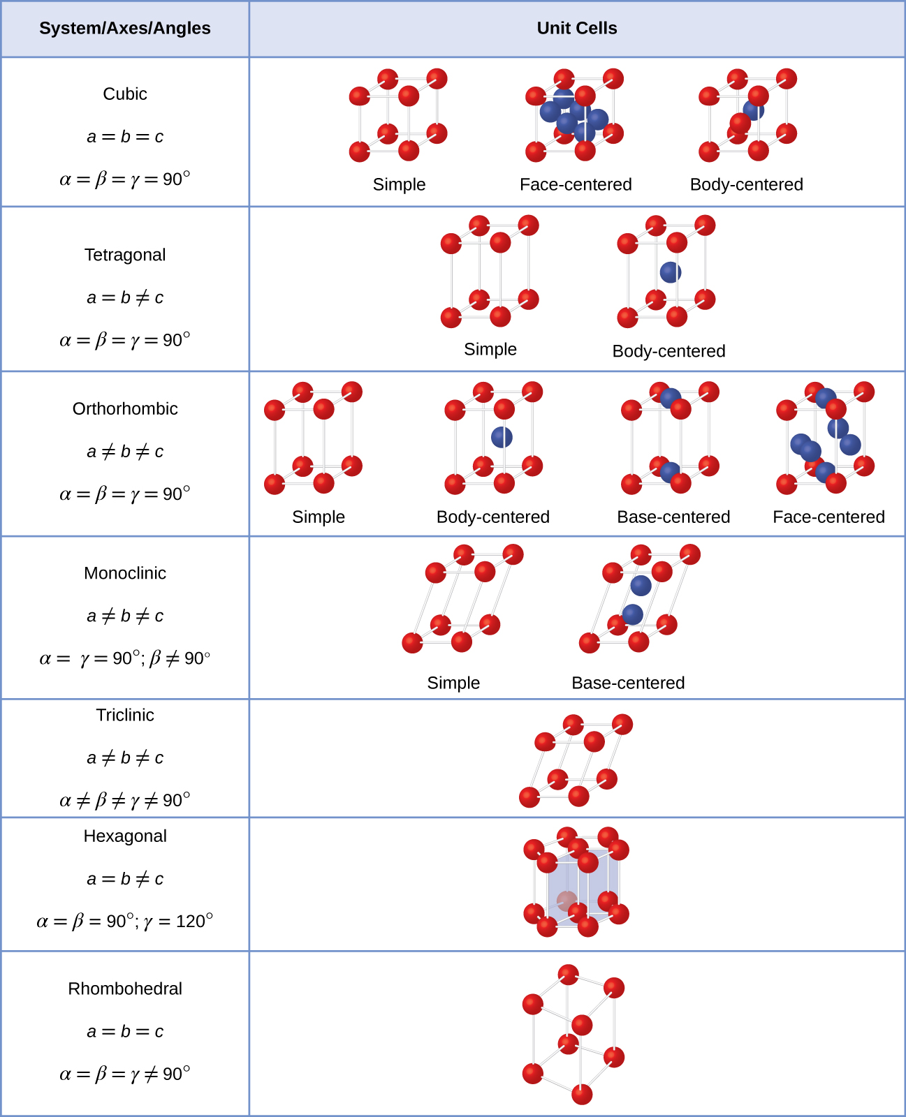
Most metal crystals are one of the four major types of unit cells. For now, we will focus on the three cubic unit cells: simple cubic , body-centered cubic unit cell, and face-centered cubic unit cell—all of which are illustrated in Figure \(\PageIndex{3}\). (Note that there are actually seven different lattice systems, some of which have more than one type of lattice, for a total of 14 different types of unit cells. These are shown in Figure \(\PageIndex{4}\).)

Simple Cubic (sc)
Let us begin our investigation of crystal lattice structure and unit cells with the most straightforward structure and the most basic unit cell. To visualize this, imagine taking a large number of identical spheres, such as tennis balls, and arranging them uniformly in a container. The simplest way to do this would be to make layers in which the spheres in one layer are directly above those in the layer below, as illustrated in Figure \(\PageIndex{5}\). This arrangement is called simple cubic structure, and the unit cell is called the simple cubic unit cell or primitive cubic unit cell.

In a simple cubic structure, the spheres are not packed as closely as they could be, and they only “fill” about 52% of the volume of the container. This is a relatively inefficient arrangement, and only one metal (polonium, Po) crystallizes in a simple cubic structure. As shown in Figure \(\PageIndex{6}\), a solid with this type of arrangement consists of planes (or layers) in which each atom contacts only the four nearest neighbors in its layer; one atom directly above it in the layer above; and one atom directly below it in the layer below. The number of other particles that each particle in a crystalline solid contacts is known as its coordination number. For a polonium atom in a simple cubic array, the coordination number is, therefore, six.
 " height="200" width="463" src="/@api/deki/files/61021/CNX_Chem_10_06_SimpleCub2.jpg">
In a simple cubic lattice, the unit cell that repeats in all directions is a cube defined by the centers of eight atoms, as shown in Figure \(\PageIndex{7}\). Atoms at adjacent corners of this unit cell contact each other, so the edge length of this cell is equal to two atomic radii, or one atomic diameter. A cubic unit cell contains only the parts of these atoms that are within it. Since an atom at a corner of a simple cubic unit cell is contained by a total of eight unit cells, only one-eighth of that atom is within a specific unit cell. And since each simple cubic unit cell has one atom at each of its eight “corners,” there is \(8×\dfrac{1}{8}=1\) atom within one simple cubic unit cell.

Body-Centered Cubic (bcc)
Some metals crystallize in an arrangement that has a cubic unit cell with atoms at all of the corners and an atom in the center, as shown in Figure \(\PageIndex{8}\). This is called a body-centered cubic (BCC) solid. Atoms in the corners of a BCC unit cell do not contact each other but contact the atom in the center. A BCC unit cell contains two atoms: one-eighth of an atom at each of the eight corners (\(8×\dfrac{1}{8}=1\) atom from the corners) plus one atom from the center. Any atom in this structure touches four atoms in the layer above it and four atoms in the layer below it. Thus, an atom in a BCC structure has a coordination number of eight.

Atoms in BCC arrangements are much more efficiently packed than in a simple cubic structure, occupying about 68% of the total volume. Isomorphous metals with a BCC structure include K, Ba, Cr, Mo, W, and Fe at room temperature. (Elements or compounds that crystallize with the same structure are said to be isomorphous.)
Face-centered Cubic (fcc) / Cubic Closest Packing (ccp)
Many other metals, such as aluminum, copper, and lead, crystallize in an arrangement that has a cubic unit cell with atoms at all of the corners and at the centers of each face, as illustrated in Figure \(\PageIndex{9}\). This arrangement is called a face-centered cubic (FCC) solid. A FCC unit cell contains four atoms: one-eighth of an atom at each of the eight corners (\(8×\dfrac{1}{8}=1\) atom from the corners) and one-half of an atom on each of the six faces (\(6×\dfrac{1}{2}=3\) atoms from the faces). The atoms at the corners touch the atoms in the centers of the adjacent faces along the face diagonals of the cube. Because the atoms are on identical lattice points, they have identical environments.

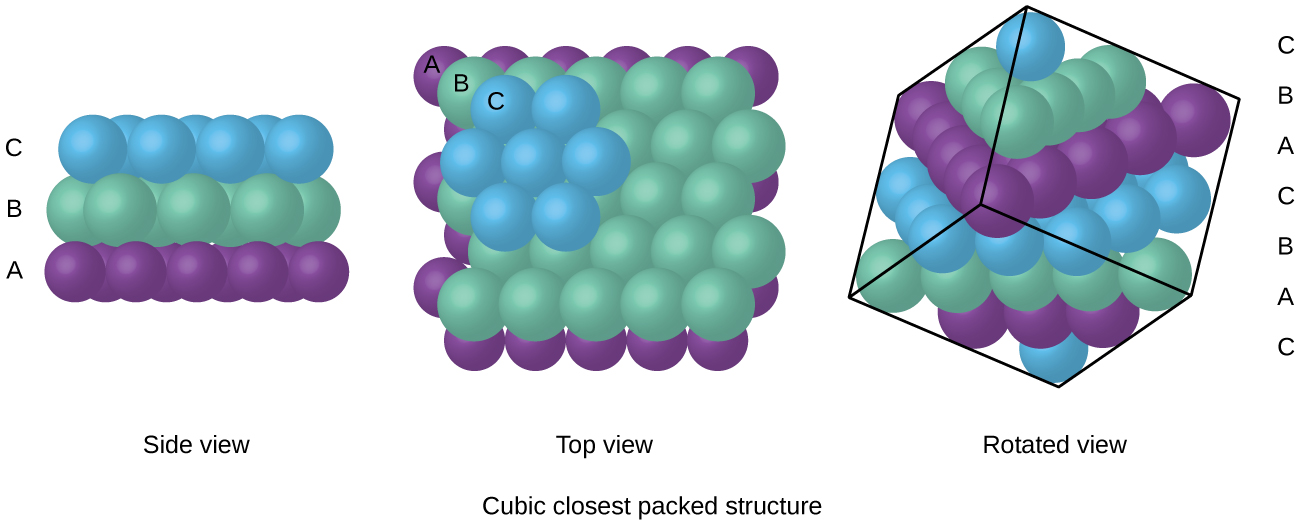
Atoms in an FCC arrangement are packed as closely together as possible, with atoms occupying 74% of the volume. This structure is also called cubic closest packing (CCP). In CCP, there are three repeating layers of hexagonally arranged atoms. Each atom contacts six atoms in its own layer, three in the layer above, and three in the layer below. In this arrangement, each atom touches 12 near neighbors, and therefore has a coordination number of 12. The fact that FCC and CCP arrangements are equivalent may not be immediately obvious, but why they are actually the same structure is illustrated in Figure \(\PageIndex{10}\).
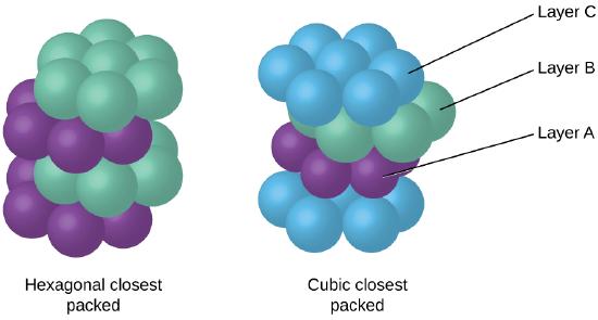
Because closer packing maximizes the overall attractions between atoms and minimizes the total intermolecular energy, the atoms in most metals pack in this manner. We find two types of closest packing in simple metallic crystalline structures: CCP, which we have already encountered, and hexagonal closest packing (HCP) shown in Figure \(\PageIndex{11}\). Both consist of repeating layers of hexagonally arranged atoms. In both types, a second layer (B) is placed on the first layer (A) so that each atom in the second layer is in contact with three atoms in the first layer. The third layer is positioned in one of two ways. In HCP, atoms in the third layer are directly above atoms in the first layer (i.e., the third layer is also type A), and the stacking consists of alternating type A and type B close-packed layers (i.e., ABABAB⋯). In CCP, atoms in the third layer are not above atoms in either of the first two layers (i.e., the third layer is type C), and the stacking consists of alternating type A, type B, and type C close-packed layers (i.e., ABCABCABC⋯). About two–thirds of all metals crystallize in closest-packed arrays with coordination numbers of 12. Metals that crystallize in an HCP structure include Cd, Co, Li, Mg, Na, and Zn, and metals that crystallize in a CCP structure include Ag, Al, Ca, Cu, Ni, Pb, and Pt.
Summary
The structures of crystalline metals and simple ionic compounds can be described in terms of packing of spheres. Metal atoms can pack in hexagonal closest-packed structures, cubic closest-packed structures, body-centered structures, and simple cubic structures.