
5.3: Lattice Structures in Ionic Solids
- Page ID
- 460913
\( \newcommand{\vecs}[1]{\overset { \scriptstyle \rightharpoonup} {\mathbf{#1}} } \)
\( \newcommand{\vecd}[1]{\overset{-\!-\!\rightharpoonup}{\vphantom{a}\smash {#1}}} \)
\( \newcommand{\id}{\mathrm{id}}\) \( \newcommand{\Span}{\mathrm{span}}\)
( \newcommand{\kernel}{\mathrm{null}\,}\) \( \newcommand{\range}{\mathrm{range}\,}\)
\( \newcommand{\RealPart}{\mathrm{Re}}\) \( \newcommand{\ImaginaryPart}{\mathrm{Im}}\)
\( \newcommand{\Argument}{\mathrm{Arg}}\) \( \newcommand{\norm}[1]{\| #1 \|}\)
\( \newcommand{\inner}[2]{\langle #1, #2 \rangle}\)
\( \newcommand{\Span}{\mathrm{span}}\)
\( \newcommand{\id}{\mathrm{id}}\)
\( \newcommand{\Span}{\mathrm{span}}\)
\( \newcommand{\kernel}{\mathrm{null}\,}\)
\( \newcommand{\range}{\mathrm{range}\,}\)
\( \newcommand{\RealPart}{\mathrm{Re}}\)
\( \newcommand{\ImaginaryPart}{\mathrm{Im}}\)
\( \newcommand{\Argument}{\mathrm{Arg}}\)
\( \newcommand{\norm}[1]{\| #1 \|}\)
\( \newcommand{\inner}[2]{\langle #1, #2 \rangle}\)
\( \newcommand{\Span}{\mathrm{span}}\) \( \newcommand{\AA}{\unicode[.8,0]{x212B}}\)
\( \newcommand{\vectorA}[1]{\vec{#1}} % arrow\)
\( \newcommand{\vectorAt}[1]{\vec{\text{#1}}} % arrow\)
\( \newcommand{\vectorB}[1]{\overset { \scriptstyle \rightharpoonup} {\mathbf{#1}} } \)
\( \newcommand{\vectorC}[1]{\textbf{#1}} \)
\( \newcommand{\vectorD}[1]{\overrightarrow{#1}} \)
\( \newcommand{\vectorDt}[1]{\overrightarrow{\text{#1}}} \)
\( \newcommand{\vectE}[1]{\overset{-\!-\!\rightharpoonup}{\vphantom{a}\smash{\mathbf {#1}}}} \)
\( \newcommand{\vecs}[1]{\overset { \scriptstyle \rightharpoonup} {\mathbf{#1}} } \)
\( \newcommand{\vecd}[1]{\overset{-\!-\!\rightharpoonup}{\vphantom{a}\smash {#1}}} \)
\(\newcommand{\avec}{\mathbf a}\) \(\newcommand{\bvec}{\mathbf b}\) \(\newcommand{\cvec}{\mathbf c}\) \(\newcommand{\dvec}{\mathbf d}\) \(\newcommand{\dtil}{\widetilde{\mathbf d}}\) \(\newcommand{\evec}{\mathbf e}\) \(\newcommand{\fvec}{\mathbf f}\) \(\newcommand{\nvec}{\mathbf n}\) \(\newcommand{\pvec}{\mathbf p}\) \(\newcommand{\qvec}{\mathbf q}\) \(\newcommand{\svec}{\mathbf s}\) \(\newcommand{\tvec}{\mathbf t}\) \(\newcommand{\uvec}{\mathbf u}\) \(\newcommand{\vvec}{\mathbf v}\) \(\newcommand{\wvec}{\mathbf w}\) \(\newcommand{\xvec}{\mathbf x}\) \(\newcommand{\yvec}{\mathbf y}\) \(\newcommand{\zvec}{\mathbf z}\) \(\newcommand{\rvec}{\mathbf r}\) \(\newcommand{\mvec}{\mathbf m}\) \(\newcommand{\zerovec}{\mathbf 0}\) \(\newcommand{\onevec}{\mathbf 1}\) \(\newcommand{\real}{\mathbb R}\) \(\newcommand{\twovec}[2]{\left[\begin{array}{r}#1 \\ #2 \end{array}\right]}\) \(\newcommand{\ctwovec}[2]{\left[\begin{array}{c}#1 \\ #2 \end{array}\right]}\) \(\newcommand{\threevec}[3]{\left[\begin{array}{r}#1 \\ #2 \\ #3 \end{array}\right]}\) \(\newcommand{\cthreevec}[3]{\left[\begin{array}{c}#1 \\ #2 \\ #3 \end{array}\right]}\) \(\newcommand{\fourvec}[4]{\left[\begin{array}{r}#1 \\ #2 \\ #3 \\ #4 \end{array}\right]}\) \(\newcommand{\cfourvec}[4]{\left[\begin{array}{c}#1 \\ #2 \\ #3 \\ #4 \end{array}\right]}\) \(\newcommand{\fivevec}[5]{\left[\begin{array}{r}#1 \\ #2 \\ #3 \\ #4 \\ #5 \\ \end{array}\right]}\) \(\newcommand{\cfivevec}[5]{\left[\begin{array}{c}#1 \\ #2 \\ #3 \\ #4 \\ #5 \\ \end{array}\right]}\) \(\newcommand{\mattwo}[4]{\left[\begin{array}{rr}#1 \amp #2 \\ #3 \amp #4 \\ \end{array}\right]}\) \(\newcommand{\laspan}[1]{\text{Span}\{#1\}}\) \(\newcommand{\bcal}{\cal B}\) \(\newcommand{\ccal}{\cal C}\) \(\newcommand{\scal}{\cal S}\) \(\newcommand{\wcal}{\cal W}\) \(\newcommand{\ecal}{\cal E}\) \(\newcommand{\coords}[2]{\left\{#1\right\}_{#2}}\) \(\newcommand{\gray}[1]{\color{gray}{#1}}\) \(\newcommand{\lgray}[1]{\color{lightgray}{#1}}\) \(\newcommand{\rank}{\operatorname{rank}}\) \(\newcommand{\row}{\text{Row}}\) \(\newcommand{\col}{\text{Col}}\) \(\renewcommand{\row}{\text{Row}}\) \(\newcommand{\nul}{\text{Nul}}\) \(\newcommand{\var}{\text{Var}}\) \(\newcommand{\corr}{\text{corr}}\) \(\newcommand{\len}[1]{\left|#1\right|}\) \(\newcommand{\bbar}{\overline{\bvec}}\) \(\newcommand{\bhat}{\widehat{\bvec}}\) \(\newcommand{\bperp}{\bvec^\perp}\) \(\newcommand{\xhat}{\widehat{\xvec}}\) \(\newcommand{\vhat}{\widehat{\vvec}}\) \(\newcommand{\uhat}{\widehat{\uvec}}\) \(\newcommand{\what}{\widehat{\wvec}}\) \(\newcommand{\Sighat}{\widehat{\Sigma}}\) \(\newcommand{\lt}{<}\) \(\newcommand{\gt}{>}\) \(\newcommand{\amp}{&}\) \(\definecolor{fillinmathshade}{gray}{0.9}\)The Structures of Crystalline Ionic Solids
Ionic crystals consist of two or more different kinds of ions that usually have different sizes. The packing of these ions into a crystal structure is more complex than the packing of metal atoms that are the same size. Most monatomic ions behave as charged spheres, and their attraction for ions of opposite charge is the same in every direction. Consequently, stable structures for ionic compounds result (1) when ions of one charge are surrounded by as many ions as possible of the opposite charge and (2) when the cations and anions are in contact with each other. Structures are determined by two principal factors: the relative sizes of the ions and the ratio of the numbers of positive and negative ions in the compound.
Anions are generally larger than their neutral atom due to the additional electrons attracted to the nucleus. Likewise, cations are generally smaller than their neutral atom due to having fewer electrons attracted to the nucleus. In simple ionic structures, we usually find the larger anions arranged in a closest-packed array. The smaller cations commonly occupy one of two types of holes (or interstices or interstitial sites) that are located between the anions. The smaller type of hole is found between three anions in one plane and one anion in an adjacent plane. The four anions surrounding this hole are arranged at the corners of a tetrahedron, so the hole is called a tetrahedral hole. The larger type of hole is found at the center of six anions (three in one layer and three in an adjacent layer) located at the corners of an octahedron; this is called an octahedral hole. Figure \(\PageIndex{1}\) illustrates both of these types of holes.

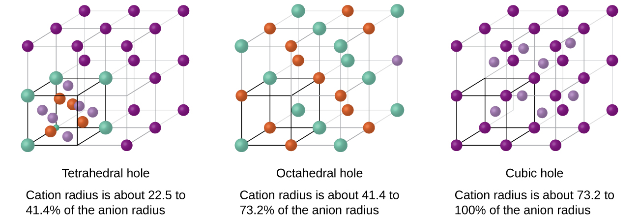
Depending on the relative sizes of the cations and anions, the cations of an ionic compound may occupy tetrahedral or octahedral holes, as illustrated in Figure \(\PageIndex{2}\). Relatively small cations occupy tetrahedral holes, and larger cations occupy octahedral holes. If the cations are too large to fit into the octahedral holes, the anions may adopt a more open structure, such as a simple cubic array. The larger cations can then occupy the larger cubic holes made possible by the more open spacing.
There are two tetrahedral holes for each anion in either an HCP or CCP array of anions. A compound that crystallizes in a closest-packed array of anions with cations in the tetrahedral holes can have a maximum cation:anion ratio of 2:1; all of the tetrahedral holes are filled at this ratio. Examples include Li2O, Na2O, Li2S, and Na2S. Compounds with a ratio of less than 2:1 may also crystallize in a closest-packed array of anions with cations in the tetrahedral holes, if the ionic sizes fit. In these compounds, however, some of the tetrahedral holes remain vacant.
Therere is one octahedral hole for each anion in either an HCP or CCP structure . Thus, compounds with cations in octahedral holes in a closest-packed array of anions can have a maximum cation:anion ratio of 1:1. In NiO, MnS, NaCl, and KH, for example, all of the octahedral holes are filled. Ratios of less than 1:1 are observed when some of the octahedral holes remain empty.
In a simple cubic array of anions, there is one cubic hole that can be occupied by a cation for each anion in the array. In CsCl, and in other compounds with the same structure, all of the cubic holes are occupied. Half of the cubic holes are occupied in SrH2, UO2, SrCl2, and CaF2.
Zinc sulfide is an important industrial source of zinc and is also used as a white pigment in paint. Zinc sulfide crystallizes with zinc ions occupying one-half of the tetrahedral holes in a closest-packed array of sulfide ions. What is the formula of zinc sulfide?
Solution
Because there are two tetrahedral holes per anion (sulfide ion) and one-half of these holes are occupied by zinc ions, there must be \(\dfrac{1}{2}×2\), or 1, zinc ion per sulfide ion. Thus, the formula is ZnS.
Aluminum oxide crystallizes with aluminum ions in two-thirds of the octahedral holes in a closest-packed array of oxide ions. What is the formula of aluminum oxide?
Solution
Because there is one octahedral hole per anion (oxide ion) and only two-thirds of these holes are occupied, the ratio of aluminum to oxygen must be \(\dfrac{2}{3}\):1, which would give \(\mathrm{Al_{2/3}O}\). The simplest whole number ratio is 2:3, so the formula is Al2O3.
Unit Cells of Ionic Compounds
Different types of ionic compounds often crystallize in the same structure when the relative sizes of their ions and their stoichiometries (the two principal features that determine structure) are similar.
Cubic Unit Cells
Many ionic compounds crystallize with cubic unit cells, and we will use these compounds to describe the general features of ionic structures. When an ionic compound is composed of cations and anions of similar size in a 1:1 ratio, it typically forms a simple cubic structure. Cesium chloride, CsCl, (Figure \(\PageIndex{3}\)) is an example of this, with Cs+ and Cl− having radii of 174 pm and 181 pm, respectively. We can think of this as chloride ions forming a simple cubic unit cell, with a cesium ion in the center; or as cesium ions forming a unit cell with a chloride ion in the center; or as simple cubic unit cells formed by Cs+ ions overlapping unit cells formed by Cl− ions. Cesium ions and chloride ions touch along the body diagonals of the unit cells. One cesium ion and one chloride ion are present per unit cell, giving the l:l stoichiometry required by the formula for cesium chloride. Note that there is no lattice point in the center of the cell, and CsCl is not a BCC structure because a cesium ion is not identical to a chloride ion.
.png?revision=1&size=bestfit&width=410&height=410) Figure \(\PageIndex{3}\): Ionic compounds with similar-sized cations and anions, such as CsCl, usually form a simple cubic structure. They can be described by unit cells with either cations at the corners or anions at the corners.
Figure \(\PageIndex{3}\): Ionic compounds with similar-sized cations and anions, such as CsCl, usually form a simple cubic structure. They can be described by unit cells with either cations at the corners or anions at the corners.We have said that the location of lattice points is arbitrary. This is illustrated by an alternate description of the CsCl structure in which the lattice points are located in the centers of the cesium ions. In this description, the cesium ions are located on the lattice points at the corners of the cell, and the chloride ion is located at the center of the cell. The two unit cells are different, but they describe identical structures.
Face-Centered Cubic Unit Cells
When an ionic compound is composed of a 1:1 ratio of cations and anions that differ significantly in size, it typically crystallizes with an FCC unit cell, like that shown in Figure \(\PageIndex{4}\). Sodium chloride, NaCl, is an example of this, with Na+ and Cl− having radii of 102 pm and 181 pm, respectively. We can think of this as chloride ions forming an FCC cell, with sodium ions located in the octahedral holes in the middle of the cell edges and in the center of the cell. The sodium and chloride ions touch each other along the cell edges. The unit cell contains four sodium ions and four chloride ions, giving the 1:1 stoichiometry required by the formula, NaCl.
 Figure \(\PageIndex{4}\): Ionic compounds with anions that are much larger than cations, such as NaCl, usually form an FCC structure. They can be described by FCC unit cells with cations in the octahedral holes. [LibreText]
The cubic form of zinc sulfide, zinc blende, also crystallizes in an FCC unit cell, as illustrated in Figure \(\PageIndex{5}\). This structure contains sulfide ions on the lattice points of an FCC lattice. (The arrangement of sulfide ions is identical to the arrangement of chloride ions in sodium chloride.) The radius of a zinc ion is only about 40% of the radius of a sulfide ion, so these small Zn2+ ions are located in alternating tetrahedral holes, that is, in one half of the tetrahedral holes. There are four zinc ions and four sulfide ions in the unit cell, giving the empirical formula ZnS.

A calcium fluoride unit cell, like that shown in Figure \(\PageIndex{6}\), is also an FCC unit cell, but in this case, the cations are located on the lattice points; equivalent calcium ions are located on the lattice points of an FCC lattice. All of the tetrahedral sites in the FCC array of calcium ions are occupied by fluoride ions. There are four calcium ions and eight fluoride ions in a unit cell, giving a calcium:fluorine ratio of 1:2, as required by the chemical formula, CaF2. Close examination of Figure \(\PageIndex{6}\) will reveal a simple cubic array of fluoride ions with calcium ions in one half of the cubic holes. The structure cannot be described in terms of a space lattice of points on the fluoride ions because the fluoride ions do not all have identical environments. The orientation of the four calcium ions about the fluoride ions differs.

Summary
The structures of crystalline metals and simple ionic compounds can be described in terms of packing of spheres. The anions in simple ionic structures commonly adopt one of these structures, and the cations occupy the spaces remaining between the anions. Small cations usually occupy tetrahedral holes in a closest-packed array of anions. Larger cations usually occupy octahedral holes. Still larger cations can occupy cubic holes in a simple cubic array of anions. The structure of a solid can be described by indicating the size and shape of a unit cell and the contents of the cell.
Problems
Lithium selenide can be described as a closest-packed array of selenide ions with lithium ions in all of the tetrahedral holes. What it the formula of lithium selenide?
- Answer
-
\(\ce{Li2Se}\)
The white pigment titanium oxide crystallizes with titanium ions in one-half of the octahedral holes in a closest-packed array of oxide ions. What is the formula of titanium oxide?
- Answer
-
\(\ce{TiO2}\)