
1.9: Analog to Digital Conversion
- Page ID
- 212105

\( \newcommand{\vecs}[1]{\overset { \scriptstyle \rightharpoonup} {\mathbf{#1}} } \)
\( \newcommand{\vecd}[1]{\overset{-\!-\!\rightharpoonup}{\vphantom{a}\smash {#1}}} \)
\( \newcommand{\id}{\mathrm{id}}\) \( \newcommand{\Span}{\mathrm{span}}\)
( \newcommand{\kernel}{\mathrm{null}\,}\) \( \newcommand{\range}{\mathrm{range}\,}\)
\( \newcommand{\RealPart}{\mathrm{Re}}\) \( \newcommand{\ImaginaryPart}{\mathrm{Im}}\)
\( \newcommand{\Argument}{\mathrm{Arg}}\) \( \newcommand{\norm}[1]{\| #1 \|}\)
\( \newcommand{\inner}[2]{\langle #1, #2 \rangle}\)
\( \newcommand{\Span}{\mathrm{span}}\)
\( \newcommand{\id}{\mathrm{id}}\)
\( \newcommand{\Span}{\mathrm{span}}\)
\( \newcommand{\kernel}{\mathrm{null}\,}\)
\( \newcommand{\range}{\mathrm{range}\,}\)
\( \newcommand{\RealPart}{\mathrm{Re}}\)
\( \newcommand{\ImaginaryPart}{\mathrm{Im}}\)
\( \newcommand{\Argument}{\mathrm{Arg}}\)
\( \newcommand{\norm}[1]{\| #1 \|}\)
\( \newcommand{\inner}[2]{\langle #1, #2 \rangle}\)
\( \newcommand{\Span}{\mathrm{span}}\) \( \newcommand{\AA}{\unicode[.8,0]{x212B}}\)
\( \newcommand{\vectorA}[1]{\vec{#1}} % arrow\)
\( \newcommand{\vectorAt}[1]{\vec{\text{#1}}} % arrow\)
\( \newcommand{\vectorB}[1]{\overset { \scriptstyle \rightharpoonup} {\mathbf{#1}} } \)
\( \newcommand{\vectorC}[1]{\textbf{#1}} \)
\( \newcommand{\vectorD}[1]{\overrightarrow{#1}} \)
\( \newcommand{\vectorDt}[1]{\overrightarrow{\text{#1}}} \)
\( \newcommand{\vectE}[1]{\overset{-\!-\!\rightharpoonup}{\vphantom{a}\smash{\mathbf {#1}}}} \)
\( \newcommand{\vecs}[1]{\overset { \scriptstyle \rightharpoonup} {\mathbf{#1}} } \)
\( \newcommand{\vecd}[1]{\overset{-\!-\!\rightharpoonup}{\vphantom{a}\smash {#1}}} \)
\(\newcommand{\avec}{\mathbf a}\) \(\newcommand{\bvec}{\mathbf b}\) \(\newcommand{\cvec}{\mathbf c}\) \(\newcommand{\dvec}{\mathbf d}\) \(\newcommand{\dtil}{\widetilde{\mathbf d}}\) \(\newcommand{\evec}{\mathbf e}\) \(\newcommand{\fvec}{\mathbf f}\) \(\newcommand{\nvec}{\mathbf n}\) \(\newcommand{\pvec}{\mathbf p}\) \(\newcommand{\qvec}{\mathbf q}\) \(\newcommand{\svec}{\mathbf s}\) \(\newcommand{\tvec}{\mathbf t}\) \(\newcommand{\uvec}{\mathbf u}\) \(\newcommand{\vvec}{\mathbf v}\) \(\newcommand{\wvec}{\mathbf w}\) \(\newcommand{\xvec}{\mathbf x}\) \(\newcommand{\yvec}{\mathbf y}\) \(\newcommand{\zvec}{\mathbf z}\) \(\newcommand{\rvec}{\mathbf r}\) \(\newcommand{\mvec}{\mathbf m}\) \(\newcommand{\zerovec}{\mathbf 0}\) \(\newcommand{\onevec}{\mathbf 1}\) \(\newcommand{\real}{\mathbb R}\) \(\newcommand{\twovec}[2]{\left[\begin{array}{r}#1 \\ #2 \end{array}\right]}\) \(\newcommand{\ctwovec}[2]{\left[\begin{array}{c}#1 \\ #2 \end{array}\right]}\) \(\newcommand{\threevec}[3]{\left[\begin{array}{r}#1 \\ #2 \\ #3 \end{array}\right]}\) \(\newcommand{\cthreevec}[3]{\left[\begin{array}{c}#1 \\ #2 \\ #3 \end{array}\right]}\) \(\newcommand{\fourvec}[4]{\left[\begin{array}{r}#1 \\ #2 \\ #3 \\ #4 \end{array}\right]}\) \(\newcommand{\cfourvec}[4]{\left[\begin{array}{c}#1 \\ #2 \\ #3 \\ #4 \end{array}\right]}\) \(\newcommand{\fivevec}[5]{\left[\begin{array}{r}#1 \\ #2 \\ #3 \\ #4 \\ #5 \\ \end{array}\right]}\) \(\newcommand{\cfivevec}[5]{\left[\begin{array}{c}#1 \\ #2 \\ #3 \\ #4 \\ #5 \\ \end{array}\right]}\) \(\newcommand{\mattwo}[4]{\left[\begin{array}{rr}#1 \amp #2 \\ #3 \amp #4 \\ \end{array}\right]}\) \(\newcommand{\laspan}[1]{\text{Span}\{#1\}}\) \(\newcommand{\bcal}{\cal B}\) \(\newcommand{\ccal}{\cal C}\) \(\newcommand{\scal}{\cal S}\) \(\newcommand{\wcal}{\cal W}\) \(\newcommand{\ecal}{\cal E}\) \(\newcommand{\coords}[2]{\left\{#1\right\}_{#2}}\) \(\newcommand{\gray}[1]{\color{gray}{#1}}\) \(\newcommand{\lgray}[1]{\color{lightgray}{#1}}\) \(\newcommand{\rank}{\operatorname{rank}}\) \(\newcommand{\row}{\text{Row}}\) \(\newcommand{\col}{\text{Col}}\) \(\renewcommand{\row}{\text{Row}}\) \(\newcommand{\nul}{\text{Nul}}\) \(\newcommand{\var}{\text{Var}}\) \(\newcommand{\corr}{\text{corr}}\) \(\newcommand{\len}[1]{\left|#1\right|}\) \(\newcommand{\bbar}{\overline{\bvec}}\) \(\newcommand{\bhat}{\widehat{\bvec}}\) \(\newcommand{\bperp}{\bvec^\perp}\) \(\newcommand{\xhat}{\widehat{\xvec}}\) \(\newcommand{\vhat}{\widehat{\vvec}}\) \(\newcommand{\uhat}{\widehat{\uvec}}\) \(\newcommand{\what}{\widehat{\wvec}}\) \(\newcommand{\Sighat}{\widehat{\Sigma}}\) \(\newcommand{\lt}{<}\) \(\newcommand{\gt}{>}\) \(\newcommand{\amp}{&}\) \(\definecolor{fillinmathshade}{gray}{0.9}\)hypothes.is tag: s20iostiot09ualr
Download Assignment: S2020IOT09
Learning Objectives
Students will be able to:
Content:
- Analog to digital converters change voltage to digital signals
- Temperature sensors sense changes in heat through heat sensitive resistors or heat sensitive diodes.
- Light sensors are light sensitive resistors or diodes.
Process:
- Build a circuit to measure light and temperature using analog to digital converters
- Use python programming to use data collected from analog to digital converters
- Use MAX31855 thermocouple amplifier to measure changes in temperature.
Prior Knowledge
- Python and IoT concepts from previous Activities
Further Reading
- https://learn.adafruit.com/tmp36-temperature-sensor/overview
- http://www.resistorguide.com/photoresistor/
Task 1: View the following YouTube videos on Analog to Digital Converters
The explanation of the analog vs digital signals
Information: MCP3008 integrated circuit chip
The Raspberry Pi computer does not have the ability to read analog signals, therefore we need to change them to digital signals. This is accomplished using an MCP3008 integrated circuit chip. This is a 10 bit chip (1024 steps) from 0 to 1 in the range of voltages that we are using. It can monitor eight analog inputs using the SPI communication protocol we used in the last activity.
This chip has 16 pins, and are numbered according to the following diagram. Pin one is indicated on the chip with a little “dimple” on the top of the chip(indicated with the arrow below). The eight analog inputs are found on the side with the dimple, and all other connections are done on the other side.
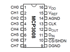
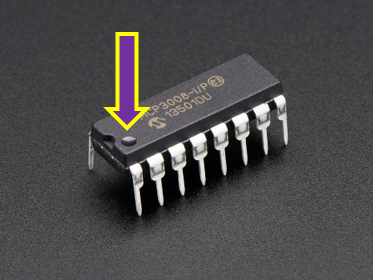
Figure \(\PageIndex{2}\): Pin one is indicated with a little “dimple”
VDD connected to 3.3V and provides the power for the chip. DGND (digital ground) is the ground for the chip itself.
The four SPI data pins are:
- DOUT (Data out from MCP3008) and connects to MISO (Master Input Slave Output)
- DIN (Data in from Raspberry Pi) and connects to MOSI (Master Output Slave Input)
- CLK (Clock Pin) and connects to the serial clock (CLK)
- CS (Chip Select) and connect to CE0
Finally the last two pins are the VREF (Reference Voltage) and the AGND (Analog Ground), which are used to change the scale. We are using 3.3V for our scale.
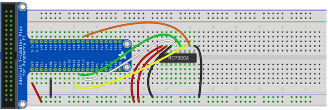
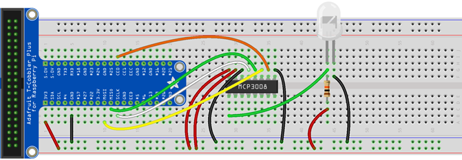
Task 2A: Start to build a circuit with an MCP3008 ADC chip
Using your breadboard with Adafruit cobbler. Place the MCP3008 chip on the board. Connect the pins using the Male to Male leads in your kit.
Pin 16 (VDD) connects to your positive rail
Pin 15 (VREF) connects to your positive rail
Pin 14 (AGND) connects to your ground rail
Pin 13 (CLK) connects to SCLK on your Adafruit cobbler (Board pin 23)
Pin 12(DOUT) connects to MISO on your Adafruit cobbler (Board pin 21)
Pin 11(DIN) connects to MOSI on your Adafruit cobbler (Board pin 19)
Pin 10 (CS) connects to CE0 on your Adafruit cobbler (Board pin 24)
Pin 9(DGND) connects to your ground rail
Information: Ambient Light Detector
Diodes only allow current to flow in one direction; that is why your LED lights only work when properly connected. The photo transistor light sensor shown below is a the reverse of an LED (light emitting diode) where instead of producing light, it takes in light and induces current to flow. The long lead is connected to ground, and the short lead is connected to a 10kW resistor. When there is no light, no current flows, and the analog voltage is near ground. When light hits the sensor, current flows, and voltage increases.
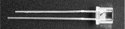
Task 2B: Connect a light sensor to your MCP3008 ADC chip
Connect the long wire from the light sensor to the ground rail. Connect the short wire to the 3.3V rail through a 10kW resistor. From this positive side voltage connect a new wire to Pin 1 on the MCP3008.
Task 3: Measure light values
For this task, enter and execute the following program with your Thonny IDE on your Raspberry Pi. Save this file with IoT_08_program1.py as the filename. The value argument for MCP3008 returns a read value from the device scaled to a value between 0 and 1.
| Python Program 1 |
|---|
from gpiozero import MCP3008
from time import sleep

adc0 = MCP3008(channel=0)

while True:
    print(adc0.value)
    sleep(1)
|
Critical thinking questions:
1. What does each line of code above tell the raspberry pi to do?
2. If your circuit is built correctly, you should have values of near 1 for when there is no light hitting the sensor (place your hand over it), and near 0 when there is ample light (shine a flashlight or your phone light). Does output indicate differens in light hitting the sensor?
3. Change your python program above to contain an IF statement that prints “Hey, who turned off the light?” if you place your hand over the sensor.
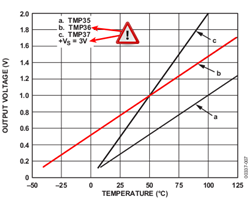
Information: TMP36
The TMP36 is a low power temperature sensor that outputs an analog signal. The voltage output is linearly proportional to the celsius temperature. The sensor uses a heat sensitive diode that changes the voltage the analog VOUT voltage allowing us to measure temperature. The device doesn’t need external calibration to provide accuracy of ±1°C at room temperature, and ±2°C over the operating range of -40°C to +125°C. The current draw is very low which means it only raises observed temperature by less than 0.1°C.
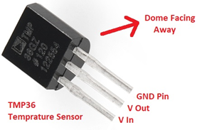
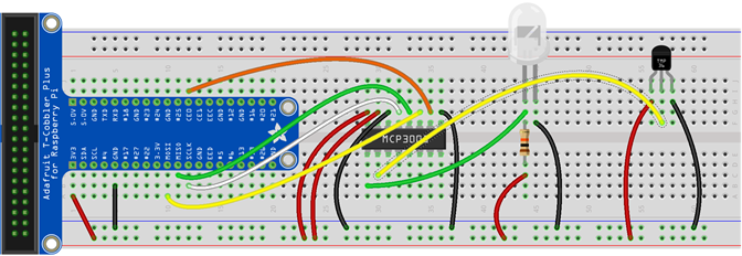
Task 4: Connect a TMP36 to your breadboard
Using the breadboard with the light sensor and MCP3008 connect your TMP36 to the circuit. You will be monitoring the TMP36 on channel 1 of the ADC. VIN goes to 3.3V on the rail with a 10KW resistor. VOUT goes to Pin 2 on the MCP3008 and GND Pin goes to ground on the rail.
Task 5: Measure light and temperature sensor values.
For this task, enter and execute the following program with your Thonny IDE on your Raspberry Pi. Save this file with IoT_08_program2.py as the filename.
| Python Program 2 |
|---|
from gpiozero import MCP3008
from time import sleep

adc0 = MCP3008(channel=0)
adc1 = MCP3008(channel=1)

while True:
    print("The value on the photoresistor is",adc0.value)
    print("The TMP digital value is", adc1.value)
    print()    sleep(1)
|
4. How does the MCP3008 know which sensor is which?
5. How does the Raspberry Pi know which sensor is which?
6. Gently grasp the TMP36 with your thumb and index fingers. What happens to the values printed to the screen? Why does this happen?
Information: TMP36 and temperature
The TMP36 device reports a 10 millivolt change for every 1°C change. If the sensor experiences a change of 100°C, the output of the device will change by 1 Volt or 1000 mV. Theoretically, the lowest voltage output would be 0 volts and the highest is 3.3 V. Because this is an imperfect device, an error voltage needs to be subtracted from the voltage reading. This is called the offset voltage. For this device the offset is 0.5 Volts. That is we need to decrease the value read on output by 0.5 V.
The values read for the TMP36 are going to be between 0 and 1, and correspond to a range of 0 to 3300 millivolts(mV). We use millivolts here instead of volts, because the specification of this device for every 1°C change, the voltage should change by 10 mV.
Therefore to convert the value from the MCP3008 to degrees C, we need to use the following equation:
Temperature = (digital value *maximum voltage value – offset voltage value)/temperature response
7. Write an equation that will allow you to convert your output from the analog to digital converter for the TMP36 sensor to degrees Celsius. How could you incorporate it into your program?
Task 6: Making meaning of the temperature data
For this task, modify IoT_08_program2 and execute the following program with your Thonny IDE on your Raspberry Pi. Save this file with IoT_08_program3.py as the filename.
| Python Program 3 |
|---|
from gpiozero import MCP3008
from time import sleep

def convert_temp(TMP36):
    return (TMP36 * 3300 - 500) / 10

adc0 = MCP3008(channel=0)
adc1 = MCP3008(channel=1)

while True:
    temp = convert_temp(adc1.value)
    print('The temperature is', temp, '\u00b0C')
    print("The value on the photoresistor is",adc0.value)
    print()    sleep(1)
|
8. In this program a function is used to convert digital values returned from a TMP36 sensor to degrees Celsius. How does this function achieve this conversion?
9. What escape character is used to allow you to print degrees Celsius to the screen?