Chapter 6.5 Delocalized Bonding and Molecular Orbitals
- Page ID
- 17713
\( \newcommand{\vecs}[1]{\overset { \scriptstyle \rightharpoonup} {\mathbf{#1}} } \)
\( \newcommand{\vecd}[1]{\overset{-\!-\!\rightharpoonup}{\vphantom{a}\smash {#1}}} \)
\( \newcommand{\id}{\mathrm{id}}\) \( \newcommand{\Span}{\mathrm{span}}\)
( \newcommand{\kernel}{\mathrm{null}\,}\) \( \newcommand{\range}{\mathrm{range}\,}\)
\( \newcommand{\RealPart}{\mathrm{Re}}\) \( \newcommand{\ImaginaryPart}{\mathrm{Im}}\)
\( \newcommand{\Argument}{\mathrm{Arg}}\) \( \newcommand{\norm}[1]{\| #1 \|}\)
\( \newcommand{\inner}[2]{\langle #1, #2 \rangle}\)
\( \newcommand{\Span}{\mathrm{span}}\)
\( \newcommand{\id}{\mathrm{id}}\)
\( \newcommand{\Span}{\mathrm{span}}\)
\( \newcommand{\kernel}{\mathrm{null}\,}\)
\( \newcommand{\range}{\mathrm{range}\,}\)
\( \newcommand{\RealPart}{\mathrm{Re}}\)
\( \newcommand{\ImaginaryPart}{\mathrm{Im}}\)
\( \newcommand{\Argument}{\mathrm{Arg}}\)
\( \newcommand{\norm}[1]{\| #1 \|}\)
\( \newcommand{\inner}[2]{\langle #1, #2 \rangle}\)
\( \newcommand{\Span}{\mathrm{span}}\) \( \newcommand{\AA}{\unicode[.8,0]{x212B}}\)
\( \newcommand{\vectorA}[1]{\vec{#1}} % arrow\)
\( \newcommand{\vectorAt}[1]{\vec{\text{#1}}} % arrow\)
\( \newcommand{\vectorB}[1]{\overset { \scriptstyle \rightharpoonup} {\mathbf{#1}} } \)
\( \newcommand{\vectorC}[1]{\textbf{#1}} \)
\( \newcommand{\vectorD}[1]{\overrightarrow{#1}} \)
\( \newcommand{\vectorDt}[1]{\overrightarrow{\text{#1}}} \)
\( \newcommand{\vectE}[1]{\overset{-\!-\!\rightharpoonup}{\vphantom{a}\smash{\mathbf {#1}}}} \)
\( \newcommand{\vecs}[1]{\overset { \scriptstyle \rightharpoonup} {\mathbf{#1}} } \)
\( \newcommand{\vecd}[1]{\overset{-\!-\!\rightharpoonup}{\vphantom{a}\smash {#1}}} \)
\(\newcommand{\avec}{\mathbf a}\) \(\newcommand{\bvec}{\mathbf b}\) \(\newcommand{\cvec}{\mathbf c}\) \(\newcommand{\dvec}{\mathbf d}\) \(\newcommand{\dtil}{\widetilde{\mathbf d}}\) \(\newcommand{\evec}{\mathbf e}\) \(\newcommand{\fvec}{\mathbf f}\) \(\newcommand{\nvec}{\mathbf n}\) \(\newcommand{\pvec}{\mathbf p}\) \(\newcommand{\qvec}{\mathbf q}\) \(\newcommand{\svec}{\mathbf s}\) \(\newcommand{\tvec}{\mathbf t}\) \(\newcommand{\uvec}{\mathbf u}\) \(\newcommand{\vvec}{\mathbf v}\) \(\newcommand{\wvec}{\mathbf w}\) \(\newcommand{\xvec}{\mathbf x}\) \(\newcommand{\yvec}{\mathbf y}\) \(\newcommand{\zvec}{\mathbf z}\) \(\newcommand{\rvec}{\mathbf r}\) \(\newcommand{\mvec}{\mathbf m}\) \(\newcommand{\zerovec}{\mathbf 0}\) \(\newcommand{\onevec}{\mathbf 1}\) \(\newcommand{\real}{\mathbb R}\) \(\newcommand{\twovec}[2]{\left[\begin{array}{r}#1 \\ #2 \end{array}\right]}\) \(\newcommand{\ctwovec}[2]{\left[\begin{array}{c}#1 \\ #2 \end{array}\right]}\) \(\newcommand{\threevec}[3]{\left[\begin{array}{r}#1 \\ #2 \\ #3 \end{array}\right]}\) \(\newcommand{\cthreevec}[3]{\left[\begin{array}{c}#1 \\ #2 \\ #3 \end{array}\right]}\) \(\newcommand{\fourvec}[4]{\left[\begin{array}{r}#1 \\ #2 \\ #3 \\ #4 \end{array}\right]}\) \(\newcommand{\cfourvec}[4]{\left[\begin{array}{c}#1 \\ #2 \\ #3 \\ #4 \end{array}\right]}\) \(\newcommand{\fivevec}[5]{\left[\begin{array}{r}#1 \\ #2 \\ #3 \\ #4 \\ #5 \\ \end{array}\right]}\) \(\newcommand{\cfivevec}[5]{\left[\begin{array}{c}#1 \\ #2 \\ #3 \\ #4 \\ #5 \\ \end{array}\right]}\) \(\newcommand{\mattwo}[4]{\left[\begin{array}{rr}#1 \amp #2 \\ #3 \amp #4 \\ \end{array}\right]}\) \(\newcommand{\laspan}[1]{\text{Span}\{#1\}}\) \(\newcommand{\bcal}{\cal B}\) \(\newcommand{\ccal}{\cal C}\) \(\newcommand{\scal}{\cal S}\) \(\newcommand{\wcal}{\cal W}\) \(\newcommand{\ecal}{\cal E}\) \(\newcommand{\coords}[2]{\left\{#1\right\}_{#2}}\) \(\newcommand{\gray}[1]{\color{gray}{#1}}\) \(\newcommand{\lgray}[1]{\color{lightgray}{#1}}\) \(\newcommand{\rank}{\operatorname{rank}}\) \(\newcommand{\row}{\text{Row}}\) \(\newcommand{\col}{\text{Col}}\) \(\renewcommand{\row}{\text{Row}}\) \(\newcommand{\nul}{\text{Nul}}\) \(\newcommand{\var}{\text{Var}}\) \(\newcommand{\corr}{\text{corr}}\) \(\newcommand{\len}[1]{\left|#1\right|}\) \(\newcommand{\bbar}{\overline{\bvec}}\) \(\newcommand{\bhat}{\widehat{\bvec}}\) \(\newcommand{\bperp}{\bvec^\perp}\) \(\newcommand{\xhat}{\widehat{\xvec}}\) \(\newcommand{\vhat}{\widehat{\vvec}}\) \(\newcommand{\uhat}{\widehat{\uvec}}\) \(\newcommand{\what}{\widehat{\wvec}}\) \(\newcommand{\Sighat}{\widehat{\Sigma}}\) \(\newcommand{\lt}{<}\) \(\newcommand{\gt}{>}\) \(\newcommand{\amp}{&}\) \(\definecolor{fillinmathshade}{gray}{0.9}\)
Learning Objectives
- To understand "resonance structures"
- To use molecular orbital theory to predict bond order.
None of the approaches we have described so far can adequately explain why some compounds are colored and others are not, why some substances with unpaired electrons are stable, and why others are effective semiconductors. These approaches also cannot describe the nature of resonance. Such limitations led to the development of a new approach to bonding in which electrons are not viewed as being localized between the nuclei of bonded atoms but are instead delocalized throughout the entire molecule. Just as with the valence bond theory, the approach we are about to discuss is based on a quantum mechanical model.
In Chapter 2, we described the electrons in isolated atoms as having certain spatial distributions, called orbitals, each with a particular orbital energy. Just as the positions and energies of electrons in atoms can be described in terms of atomic orbitals (AOs), the positions and energies of electrons in molecules can be described in terms of molecular orbitals (MOs) A particular spatial distribution of electrons in a molecule that is associated with a particular orbital energy.—a spatial distribution of electrons in a molecule that is associated with a particular orbital energy. As the name suggests, molecular orbitals are not localized on a single atom but extend over the entire molecule. Consequently, the molecular orbital approach, called molecular orbital theory A delocalized bonding model in which molecular orbitals are created from the linear combination of atomic orbitals (LCAOs), is a delocalized approach to bonding.
Note the Pattern
Molecular orbital theory is a delocalized bonding approach that explains the colors of compounds, their stability, and resonance.
Molecular Orbital Theory: A Delocalized Bonding Approach
Although the molecular orbital theory is computationally demanding, the principles on which it is based are similar to those we used to determine electron configurations for atoms. The key difference is that in molecular orbitals, the electrons are allowed to interact with more than one atomic nucleus at a time. Just as with atomic orbitals, we create an energy-level diagram by listing the molecular orbitals in order of increasing energy. We then fill the orbitals with the required number of valence electrons according to the Pauli principle. This means that each molecular orbital can accommodate a maximum of two electrons with opposite spins.
Molecular Orbitals Involving Only ns Atomic Orbitals
We begin our discussion of molecular orbitals with the simplest molecule, H2, formed from two isolated hydrogen atoms, each with a 1s1 electron configuration. As we explained in Chapter 2 electrons can behave like waves. In the molecular orbital approach, the overlapping atomic orbitals are described by mathematical equations called wave functions. (For more information on wave functions, see Section 2.5) The 1s atomic orbitals on the two hydrogen atoms interact to form two new molecular orbitals, one produced by taking the sum of the two H 1s wave functions, and the other produced by taking their difference:
\( \begin{matrix}
MO(1)= & AO(atom\; A) & +& AO(atomB) \\
MO(1)= & AO(atom\; A) & -&AO(atomB)
\end{matrix} \tag{6.5.1} \)
The molecular orbitals created from Equation 6.5.1 are called linear combinations of atomic orbitals (LCAOs) Molecular orbitals created from the sum and the difference of two wave functions (atomic orbitals). A molecule must have as many molecular orbitals as there are atomic orbitals.
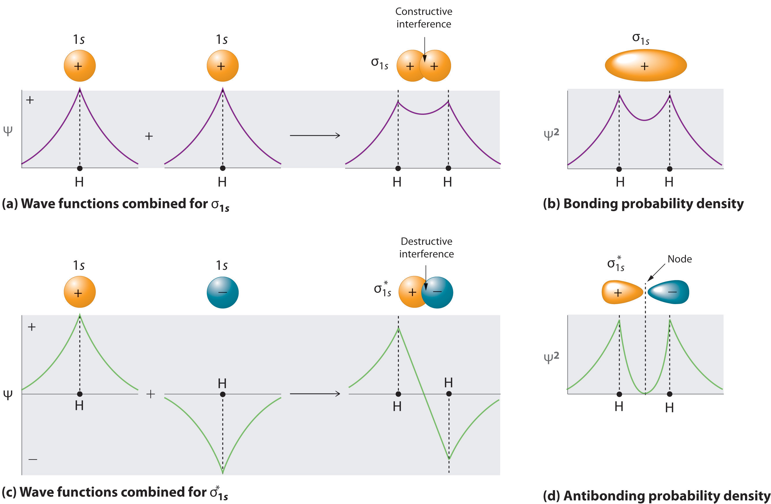
Adding two atomic orbitals corresponds to constructive interference between two waves, thus reinforcing their intensity; the internuclear electron probability density is increased. The molecular orbital corresponding to the sum of the two H 1s orbitals is called a σ1s combination (pronounced “sigma one ess”) (part (a) and part (b) in Figure 6.5.1 ). In a sigma (σ) orbital, A bonding molecular orbital in which the electron density along the internuclear axis and between the nuclei has cylindrical symmetry, the electron density along the internuclear axis and between the nuclei has cylindrical symmetry; that is, all cross-sections perpendicular to the internuclear axis are circles. The subscript 1s denotes the atomic orbitals from which the molecular orbital was derived:The ≈ sign is used rather than an = sign because we are ignoring certain constants that are not important to our argument.
Figure 6.5.1 Molecular Orbitals for the H2 Molecule
(a) This diagram shows the formation of a bonding σ1s molecular orbital for H2 as the sum of the wave functions (Ψ) of two H 1s atomic orbitals. (b) This plot of the square of the wave function (Ψ2) for the bonding σ1s molecular orbital illustrates the increased electron probability density between the two hydrogen nuclei. (Recall from Chapter 2 that the probability density is proportional to the square of the wave function.) (c) This diagram shows the formation of an antibonding \( \sigma _{1s}^{*} \) molecular orbital for H2 as the difference of the wave functions (Ψ) of two H 1s atomic orbitals. (d) This plot of the square of the wave function (Ψ2) for the \( \sigma _{1s}^{*} \) antibonding molecular orbital illustrates the node corresponding to zero electron probability density between the two hydrogen nuclei.
\( \sigma _{1s} \approx 1s\left ( A \right ) + 1s\left ( B \right ) \tag{6.5.2} \)
Conversely, subtracting one atomic orbital from another corresponds to destructive interference between two waves, which reduces their intensity and causes a decrease in the internuclear electron probability density (part (c) and part (d) in Figure 6.5.1 ). The resulting pattern contains a node where the electron density is zero. The molecular orbital corresponding to the difference is called \( \sigma _{1s}^{*} \) (“sigma one ess star”). In a sigma star (σ*) orbital An antibonding molecular orbital in which there is a region of zero electron probability (a nodal plane) perpendicular to the internuclear axis., there is a region of zero electron probability, a nodal plane, perpendicular to the internuclear axis:
\( \sigma _{1s}^{\star } \approx 1s\left ( A \right ) - 1s\left ( B \right ) \tag{6.5.3} \)
Note the Pattern
A molecule must have as many molecular orbitals as there are atomic orbitals.
The electron density in the σ1s molecular orbital is greatest between the two positively charged nuclei, and the resulting electron–nucleus electrostatic attractions reduce repulsions between the nuclei. Thus the σ1s orbital represents a bonding molecular orbital. A molecular orbital that forms when atomic orbitals or orbital lobes with the same sign interact to give increased electron probability between the nuclei due to constructive reinforcement of the wave functions. In contrast, electrons in the \( \sigma _{1s}^{\star } \) orbital are generally found in the space outside the internuclear region. Because this allows the positively charged nuclei to repel one another, the \( \sigma _{1s}^{\star } \) orbital is an antibonding molecular orbital A molecular orbital that forms when atomic orbitals or orbital lobes of opposite sign interact to give decreased electron probability between the nuclei due to destructuve reinforcement of the wave functions..
Note the Pattern
Antibonding orbitals contain a node perpendicular to the internuclear axis; bonding orbitals do not.
Energy-Level Diagrams
Because electrons in the σ1s orbital interact simultaneously with both nuclei, they have a lower energy than electrons that interact with only one nucleus. This means that the σ1s molecular orbital has a lower energy than either of the hydrogen 1s atomic orbitals. Conversely, electrons in the \( \sigma _{1s}^{\star } \) orbital interact with only one hydrogen nucleus at a time. In addition, they are farther away from the nucleus than they were in the parent hydrogen 1s atomic orbitals. Consequently, the \( \sigma _{1s}^{\star } \) molecular orbital has a higher energy than either of the hydrogen 1s atomic orbitals. The σ1s (bonding) molecular orbital is stabilized relative to the 1s atomic orbitals, and the \( \sigma _{1s}^{\star } \) (antibonding) molecular orbital is destabilized. The relative energy levels of these orbitals are shown in the energy-level diagram A schematic drawing that compares the energies of the molecular orbitals (bonding, antibonding, and nonbonding) with the energies of the parent atomic orbitals. in Figure 6.5.2
Note the Pattern
A bonding molecular orbital is always lower in energy (more stable) than the component atomic orbitals, whereas an antibonding molecular orbital is always higher in energy (less stable).
Figure 6.5.2 Molecular Orbital Energy-Level Diagram for H2
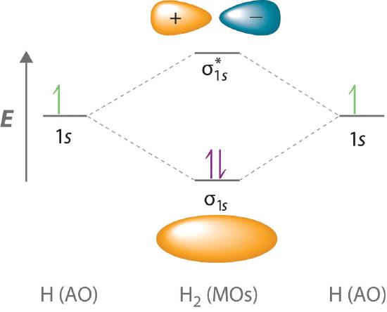
The two available electrons (one from each H atom) in this diagram fill the bonding σ1s molecular orbital. Because the energy of the σ1s molecular orbital is lower than that of the two H 1s atomic orbitals, the H2 molecule is more stable (at a lower energy) than the two isolated H atoms.
To describe the bonding in a homonuclear diatomic molecule A molecule that consists of two atoms of the same element. such as H2, we use molecular orbitals; that is, for a molecule in which two identical atoms interact, we insert the total number of valence electrons into the energy-level diagram (Figure 6.5.2 ). We fill the orbitals according to the Pauli principle and Hund’s rule: each orbital can accommodate a maximum of two electrons with opposite spins, and the orbitals are filled in order of increasing energy. Because each H atom contributes one valence electron, the resulting two electrons are exactly enough to fill the σ1s bonding molecular orbital. The two electrons enter an orbital whose energy is lower than that of the parent atomic orbitals, so the H2 molecule is more stable than the two isolated hydrogen atoms. Thus molecular orbital theory correctly predicts that H2 is a stable molecule. Because bonds form when electrons are concentrated in the space between nuclei, this approach is also consistent with our earlier discussion of electron-pair bonds.
Bond Order in Molecular Orbital Theory
In the Lewis electron structures described in Chapter 4 , the number of electron pairs holding two atoms together was called the bond order. In the molecular orbital approach, bond order One-half the net number of bonding electrons in a molecule. is defined as one-half the net number of bonding electrons:
\( bond\; order=\dfrac{number\; of \; bonding\; electrons-number\; of \; antibonding\; electrons}{2} \tag{6.5.4} \)
To calculate the bond order of H2, we see from Figure 6.5.2 that the σ1s (bonding) molecular orbital contains two electrons, while the \( \sigma _{1s}^{\star } \) (antibonding) molecular orbital is empty. The bond order of H2 is therefore
\( \dfrac{2-0}{2}=1 \tag{5.3.5} \)
This result corresponds to the single covalent bond predicted by Lewis dot symbols. Thus molecular orbital theory and the Lewis electron-pair approach agree that a single bond containing two electrons has a bond order of 1. Double and triple bonds contain four or six electrons, respectively, and correspond to bond orders of 2 and 3.
We can use energy-level diagrams such as the one in Figure 6.5.2 to describe the bonding in other pairs of atoms and ions where n = 1, such as the H2+ ion, the He2+ ion, and the He2 molecule. Again, we fill the lowest-energy molecular orbitals first while being sure not to violate the Pauli principle or Hund’s rule.
Part (a) in Figure 6.5.3 shows the energy-level diagram for the H2+ ion, which contains two protons and only one electron. The single electron occupies the σ1s bonding molecular orbital, giving a (σ1s)1 electron configuration. The number of electrons in an orbital is indicated by a superscript. In this case, the bond order is (1-0)/2=1/2 Because the bond order is greater than zero, the H2+ ion should be more stable than an isolated H atom and a proton. We can therefore use a molecular orbital energy-level diagram and the calculated bond order to predict the relative stability of species such as H2+. With a bond order of only 1/2 the bond in H2+ should be weaker than in the H2 molecule, and the H–H bond should be longer. As shown in Table 6.5.1 , these predictions agree with the experimental data.
Part (b) in Figure 5.3.3 is the molecular orbital energy-level diagram for He2+. This ion has a total of three valence electrons. Because the first two electrons completely fill the σ1s molecular orbital, the Pauli principle states that the third electron must be in the \( \sigma _{1s}^{\star} \) antibonding orbital, giving a \( \left (\sigma _{1s} \right )^{2}\left (\sigma _{1s}^{\star } \right )^{1} \) electron configuration. This electron configuration gives a bond order of (2-1)/2=1/2. As with H2+, the He2+ ion should be stable, but the He–He bond should be weaker and longer than in H2. In fact, the He2+ ion can be prepared, and its properties are consistent with our predictions (Table 6.5.1 ).
Figure 6.5.3 Molecular Orbital Energy-Level Diagrams for Diatomic Molecules with Only 1s Atomic Orbitals
(a) The H2+ ion, (b) the He2+ ion, and (c) the He2 molecule are shown here.
Table 6.5.1 Molecular Orbital Electron Configurations, Bond Orders, Bond Lengths, and Bond Energies for some Simple Homonuclear Diatomic Molecules and Ions
| Molecule or Ion | Electron Configuration | Bond Order | Bond Length (pm) | Bond Energy (kJ/mol) |
|---|---|---|---|---|
| H2+ | (σ1s)1 | 1/2 | 106 | 269 |
| H2 | (σ1s)2 | 1 | 74 | 436 |
| He2+ | \( \left (\sigma _{1s} \right )^{2}\left (\sigma _{1s}^{\star } \right )^{1} \) | 1/2 | 108 | 251 |
| He2 | \( \left (\sigma _{1s} \right )^{2}\left (\sigma _{1s}^{\star } \right )^{2} \) | 0 | not observed | not observed |
Finally, we examine the He2 molecule, formed from two He atoms with 1s2 electron configurations. Part (c) in Figure 6.5.3 is the molecular orbital energy-level diagram for He2. With a total of four valence electrons, both the σ1s bonding and \( \sigma _{1s}^{\star } \) antibonding orbitals must contain two electrons. This gives a \( \left (\sigma _{1s} \right )^{2}\left (\sigma _{1s}^{\star } \right )^{1} \) electron configuration, with a predicted bond order of (2 − 2) ÷ 2 = 0, which indicates that the He2 molecule has no net bond and is not a stable species. Experiments show that the He2 molecule is actually less stable than two isolated He atoms due to unfavorable electron–electron and nucleus–nucleus interactions.
In molecular orbital theory, electrons in antibonding orbitals effectively cancel the stabilization resulting from electrons in bonding orbitals. Consequently, any system that has equal numbers of bonding and antibonding electrons will have a bond order of 0, and it is predicted to be unstable and therefore not to exist in nature. In contrast to Lewis electron structures and the valence bond approach, molecular orbital theory is able to accommodate systems with an odd number of electrons, such as the H2+ ion.
Note the Pattern
In contrast to Lewis electron structures and the valence bond approach, molecular orbital theory can accommodate systems with an odd number of electrons.
Example 11
Use a molecular orbital energy-level diagram, such as those in Figure 6.5.3 , to predict the bond order in the He22+ ion. Is this a stable species?
Given: chemical species
Asked for: molecular orbital energy-level diagram, bond order, and stability
Strategy:
A Combine the two He valence atomic orbitals to produce bonding and antibonding molecular orbitals. Draw the molecular orbital energy-level diagram for the system.
B Determine the total number of valence electrons in the He22+ ion. Fill the molecular orbitals in the energy-level diagram beginning with the orbital with the lowest energy. Be sure to obey the Pauli principle and Hund’s rule while doing so.
C Calculate the bond order and predict whether the species is stable.
Solution:
A Two He 1s atomic orbitals combine to give two molecular orbitals: a σ1s bonding orbital at lower energy than the atomic orbitals and a \( \sigma _{1s}^{\star } \) antibonding orbital at higher energy. The bonding in any diatomic molecule with two He atoms can be described using the following molecular orbital diagram:
B The He22+ ion has only two valence electrons (two from each He atom minus two for the +2 charge). We can also view He22+ as being formed from two He+ ions, each of which has a single valence electron in the 1s atomic orbital. We can now fill the molecular orbital diagram:
The two electrons occupy the lowest-energy molecular orbital, which is the bonding (σ1s) orbital, giving a (σ1s)2 electron configuration. To avoid violating the Pauli principle, the electron spins must be paired. C So the bond order is
\( \frac{2-0}{2} =1 \)
He22+ is therefore predicted to contain a single He–He bond. Thus it should be a stable species.
Exercise
Use a molecular orbital energy-level diagram to predict the valence-electron configuration and bond order of the H22− ion. Is this a stable species?
Answer: H22− has a valence electron configuration of \( \left (\sigma _{1s} \right )^{2}\left (\sigma _{1s}^{\star } \right )^{2} \) with a bond order of 0. It is therefore predicted to be unstable.
So far, our discussion of molecular orbitals has been confined to the interaction of valence orbitals, which tend to lie farthest from the nucleus. When two atoms are close enough for their valence orbitals to overlap significantly, the filled inner electron shells are largely unperturbed; hence they do not need to be considered in a molecular orbital scheme. Also, when the inner orbitals are completely filled, they contain exactly enough electrons to completely fill both the bonding and antibonding molecular orbitals that arise from their interaction. Thus the interaction of filled shells always gives a bond order of 0, so filled shells are not a factor when predicting the stability of a species. This means that we can focus our attention on the molecular orbitals derived from valence atomic orbitals.
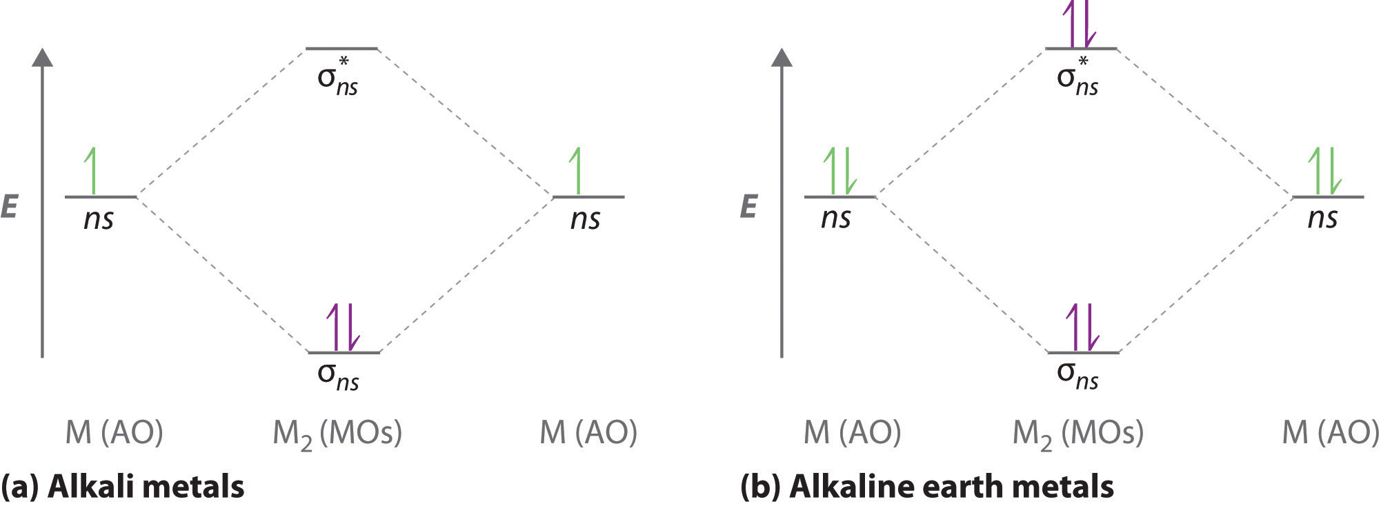
A molecular orbital diagram that can be applied to any homonuclear diatomic molecule with two identical alkali metal atoms (Li2 and Cs2, for example) is shown in part (a) in Figure 6.5.4, where M represents the metal atom. Only two energy levels are important for describing the valence electron molecular orbitals of these species: a σns bonding molecular orbital and a σ*ns antibonding molecular orbital. Because each alkali metal (M) has an ns1 valence electron configuration, the M2 molecule has two valence electrons that fill the σns bonding orbital. As a result, a bond order of 1 is predicted for all homonuclear diatomic species formed from the alkali metals (Li2, Na2, K2, Rb2, and Cs2). The general features of these M2 diagrams are identical to the diagram for the H2 molecule in Figure 6.5.2. Experimentally, all are found to be stable in the gas phase, and some are even stable in solution.
Figure 6.5.4 Molecular Orbital Energy-Level Diagrams for Alkali Metal and Alkaline Earth Metal Diatomic (M2) Molecules
(a) For alkali metal diatomic molecules, the two valence electrons are enough to fill the σns (bonding) level, giving a bond order of 1. (b) For alkaline earth metal diatomic molecules, the four valence electrons fill both the σns (bonding) and the σns* (nonbonding) levels, leading to a predicted bond order of 0.
Similarly, the molecular orbital diagrams for homonuclear diatomic compounds of the alkaline earth metals (such as Be2), in which each metal atom has an ns2 valence electron configuration, resemble the diagram for the He2 molecule in part (c) in Figure 6.5.3 As shown in part (b) in Figure 6.5.4 , this is indeed the case. All the homonuclear alkaline earth diatomic molecules have four valence electrons, which fill both the σns bonding orbital and the σns* antibonding orbital and give a bond order of 0. Thus Be2, Mg2, Ca2, Sr2, and Ba2 are all expected to be unstable, in agreement with experimental data.In the solid state, however, all the alkali metals and the alkaline earth metals exist as extended lattices held together by metallic bonding. At low temperatures, Be2 is stable.
Example 12
Use a qualitative molecular orbital energy-level diagram to predict the valence electron configuration, bond order, and likely existence of the Na2− ion.
Given: chemical species
Asked for: molecular orbital energy-level diagram, valence electron configuration, bond order, and stability
Strategy:
A Combine the two sodium valence atomic orbitals to produce bonding and antibonding molecular orbitals. Draw the molecular orbital energy-level diagram for this system.
B Determine the total number of valence electrons in the Na2− ion. Fill the molecular orbitals in the energy-level diagram beginning with the orbital with the lowest energy. Be sure to obey the Pauli principle and Hund’s rule while doing so.
C Calculate the bond order and predict whether the species is stable.
Solution:
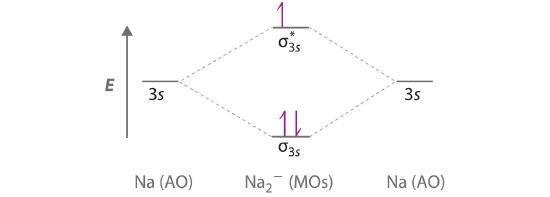
A Because sodium has a [Ne]3s1 electron configuration, the molecular orbital energy-level diagram is qualitatively identical to the diagram for the interaction of two 1s atomic orbitals. B The Na2− ion has a total of three valence electrons (one from each Na atom and one for the negative charge), resulting in a filled σ3s molecular orbital, a half-filled σ3s* and a \( \left ( \sigma _{3s} \right )^{2}\left ( \sigma _{3s}^{\star } \right )^{1} \) electron configuration.
C The bond order is (2-1)÷2=1/2 With a fractional bond order, we predict that the Na2− ion exists but is highly reactive.
Exercise
Use a qualitative molecular orbital energy-level diagram to predict the valence electron configuration, bond order, and likely existence of the Ca2+ ion.
Answer: Ca2+ has a \( \left ( \sigma _{4s} \right )^{2}\left ( \sigma _{4s}^{\star } \right )^{1} \) electron configurations and a bond order of 1/2 and should exist.
Molecular Orbitals Formed from ns and np Atomic Orbitals
Atomic orbitals other than ns orbitals can also interact to form molecular orbitals. Because individual p, d, and f orbitals are not spherically symmetrical, however, we need to define a coordinate system so we know which lobes are interacting in three-dimensional space. Recall from Section 2.5 that for each np subshell, for example, there are npx, npy, and npz orbitals (Figure 2.5.6). All have the same energy and are therefore degenerate, but they have different spatial orientations.\( \sigma _{np_{z}}=np_{z}\left ( A \right )-np_{z}\left ( B \right ) \tag{5.3.6}\)
Just as with ns orbitals, we can form molecular orbitals from np orbitals by taking their mathematical sum and difference. When two positive lobes with the appropriate spatial orientation overlap, as illustrated for two npz atomic orbitals in part (a) in Figure 6.3.5, it is the mathematical difference of their wave functions that results in constructive interference, which in turn increases the electron probability density between the two atoms. The difference therefore corresponds to a molecular orbital called a \( \sigma _{np_{z}} \) bonding molecular orbital because, just as with the σ orbitals discussed previously, it is symmetrical about the internuclear axis (in this case, the z-axis):
\( \sigma _{np_{z}}=np_{z}\left ( A \right )-np_{z}\left ( B \right ) \tag{6.5.6}\)
The other possible combination of the two npz orbitals is the mathematical sum:
\( \sigma _{np_{z}}=np_{z}\left ( A \right )+np_{z}\left ( B \right ) \tag{6.5.7}\)
In this combination, shown in part (b) in Figure 6.5.5, the positive lobe of one npz atomic orbital overlaps the negative lobe of the other, leading to destructive interference of the two waves and creating a node between the two atoms. Hence this is an antibonding molecular orbital. Because it, too, is symmetrical about the internuclear axis, this molecular orbital is called a \( \sigma _{np_{z}}=np_{z}\left ( A \right )-np_{z}\left ( B \right ) \) antibonding molecular orbital. Whenever orbitals combine, the bonding combination is always lower in energy (more stable) than the atomic orbitals from which it was derived, and the antibonding combination is higher in energy (less stable).
Figure 6.5.5 Formation of Molecular Orbitals from npz Atomic Orbitals on Adjacent Atoms
(a) By convention, in a linear molecule or ion, the z-axis always corresponds to the internuclear axis, with +z to the right. As a result, the signs of the lobes of the npz atomic orbitals on the two atoms alternate − + − +, from left to right. In this case, the σ (bonding) molecular orbital corresponds to the mathematical difference, in which the overlap of lobes with the same sign results in increased probability density between the nuclei. (b) In contrast, the σ* (antibonding) molecular orbital corresponds to the mathematical sum, in which the overlap of lobes with opposite signs results in a nodal plane of zero probability density perpendicular to the internuclear axis.
Note the Pattern
Overlap of atomic orbital lobes with the same sign produces a bonding molecular orbital, regardless of whether it corresponds to the sum or the difference of the atomic orbitals.
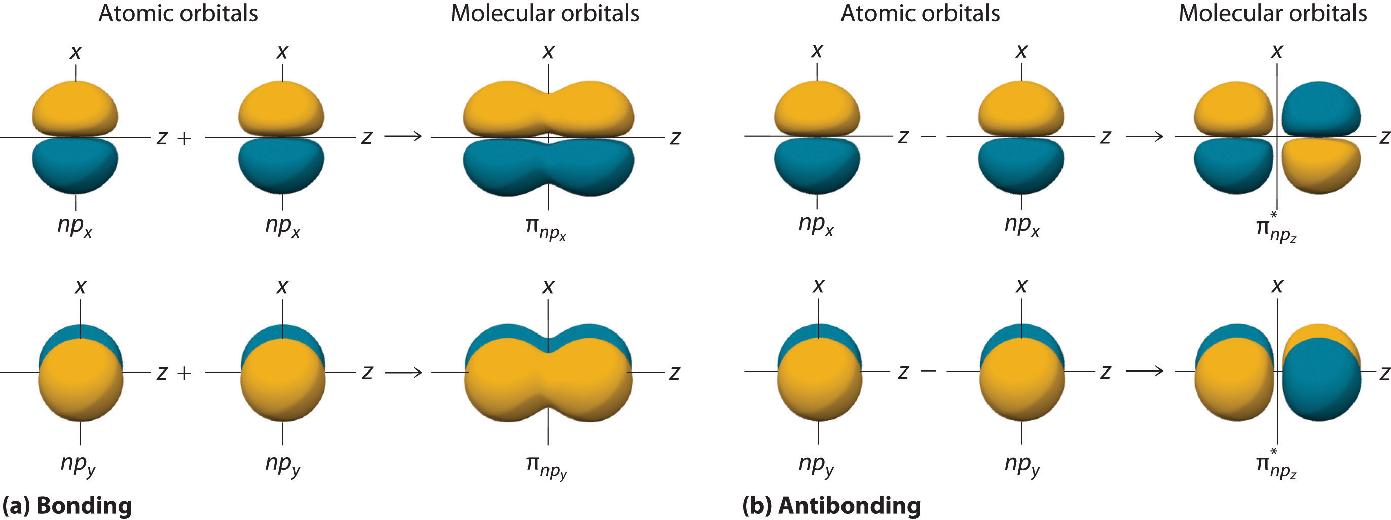
The remaining p orbitals on each of the two atoms, npx and npy, do not point directly toward each other. Instead, they are perpendicular to the internuclear axis. If we arbitrarily label the axes as shown in Figure 6.5.6, we see that we have two pairs of np orbitals: the two npx orbitals lying in the plane of the page, and two npy orbitals perpendicular to the plane. Although these two pairs are equivalent in energy, the npx orbital on one atom can interact with only the npx orbital on the other, and the npy orbital on one atom can interact with only the npy on the other. These interactions are side-to-side rather than the head-to-head interactions characteristic of σ orbitals. Each pair of overlapping atomic orbitals again forms two molecular orbitals: one corresponds to the arithmetic sum of the two atomic orbitals and one to the difference. The sum of these side-to-side interactions increases the electron probability in the region above and below a line connecting the nuclei, so it is a bonding molecular orbital that is called a pi (π) orbitalA bonding molecular orbital formed from the side-to-side interactions of two or more parallel np atomic orbitals.. The difference results in the overlap of orbital lobes with opposite signs, which produces a nodal plane perpendicular to the internuclear axis; hence it is an antibonding molecular orbital, called a pi star (π*) orbital An antibonding molecular orbital formed from the difference of the side-to-side interactions of two or more parallel np atomic orbitals, creating a nodal plane perpendicular to the internuclear axis..
\( \pi _{np_{x}}=np_{x}\left ( A \right )+np_{x}\left ( B \right ) \tag{6.5.8}\)
\( \pi ^{\star }_{np_{x}}=np_{x}\left ( A \right )-np_{x}\left ( B \right ) \tag{6.5.9}\)
The two npy orbitals can also combine using side-to-side interactions to produce a bonding \( \pi _{np_{y}} \) molecular orbital and an antibonding \( \pi _{np_{y}}^{\star } \) molecular orbital. Because the npx and npy atomic orbitals interact in the same way (side-to-side) and have the same energy, the \( \pi _{np_{x}} \) and \( \pi _{np_{y}} \)molecular orbitals are a degenerate pair, as are the \( \pi _{np_{x}}^{\star } \) and \( \pi _{np_{y}}^{\star } \) molecular orbitals.
Figure 6.5.6 Formation of π Molecular Orbitals from npx and npy Atomic Orbitals on Adjacent Atoms
(a) Because the signs of the lobes of both the npx and the npy atomic orbitals on adjacent atoms are the same, in both cases the mathematical sum corresponds to a π (bonding) molecular orbital. (b) In contrast, in both cases, the mathematical difference corresponds to a π* (antibonding) molecular orbital, with a nodal plane of zero probability density perpendicular to the internuclear axis.
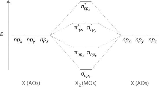
Figure 6.5.7 is an energy-level diagram that can be applied to two identical interacting atoms that have three np atomic orbitals each. There are six degenerate p atomic orbitals (three from each atom) that combine to form six molecular orbitals, three bonding and three antibonding. The bonding molecular orbitals are lower in energy than the atomic orbitals because of the increased stability associated with the formation of a bond. Conversely, the antibonding molecular orbitals are higher in energy, as shown. The energy difference between the σ and σ* molecular orbitals is significantly greater than the difference between the two π and π* sets. The reason for this is that the atomic orbital overlap and thus the strength of the interaction are greater for a σ bond than a π bond, which means that the σ molecular orbital is more stable (lower in energy) than the π molecular orbitals.
Figure 6.5.7 The Relative Energies of the σ and π Molecular Orbitals Derived from npx, npy, and npz Orbitals on Identical Adjacent Atoms
Because the two npz orbitals point directly at each other, their orbital overlap is greater, so the difference in energy between the σ and σ* molecular orbitals is greater than the energy difference between the π and π* orbitals.
Although many combinations of atomic orbitals form molecular orbitals, we will discuss only one other interaction: an ns atomic orbital on one atom with an npz atomic orbital on another. As shown in Figure 6.5.8 , the sum of the two atomic wave functions (ns + npz) produces a σ bonding molecular orbital. Their difference (ns − npz) produces a σ* antibonding molecular orbital, which has a nodal plane of zero probability density perpendicular to the internuclear axis.
Figure 6.5.8 Formation of Molecular Orbitals from an ns Atomic Orbital on One Atom and an npz Atomic Orbital on an Adjacent Atom
(a) The mathematical sum results in a σ (bonding) molecular orbital, with increased probability density between the nuclei. (b) The mathematical difference results in a σ* (antibonding) molecular orbital, with a nodal plane of zero probability density perpendicular to the internuclear axis.
Molecular Orbital Diagrams for Period 2 Homonuclear Diatomic Molecules
We now describe examples of systems involving period 2 homonuclear diatomic molecules, such as N2, O2, and F2. When we draw a molecular orbital diagram for a molecule, there are four key points to remember:
- The number of molecular orbitals produced is the same as the number of atomic orbitals used to create them (the law of conservation of orbitals A law that states that the number of molecular orbitals produced is the same as the number of atomic orbitals used to create them.).
- As the overlap between two atomic orbitals increases, the difference in energy between the resulting bonding and antibonding molecular orbitals increases.
- When two atomic orbitals combine to form a pair of molecular orbitals, the bonding molecular orbital is stabilized about as much as the antibonding molecular orbital is destabilized.
- The interaction between atomic orbitals is greatest when they have the same energy.
Note the Pattern
The number of molecular orbitals is always equal to the total number of atomic orbitals we started with.
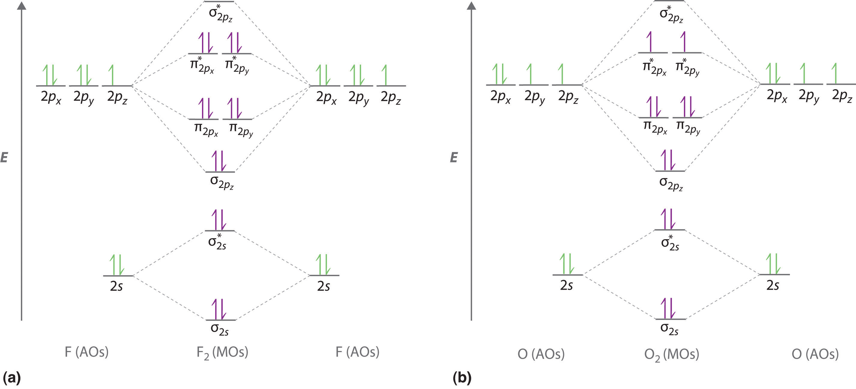
We illustrate how to use these points by constructing a molecular orbital energy-level diagram for F2. We use the diagram in part (a) in Figure 6.5.9 ; the n = 1 orbitals (σ1s and σ1s*) are located well below those of the n = 2 level and are not shown. As illustrated in the diagram, the σ2s and σ2s* molecular orbitals are much lower in energy than the molecular orbitals derived from the 2p atomic orbitals because of the large difference in energy between the 2s and 2p atomic orbitals of fluorine. The lowest-energy molecular orbital derived from the three 2p orbitals on each F is \( \sigma _{2p_{z}} \) and the next most stable are the two degenerate orbitals, \( \pi _{2p_{x}} \) and \( \pi _{2p_{y}} \). For each bonding orbital in the diagram, there is an antibonding orbital, and the antibonding orbital is destabilized by about as much as the corresponding bonding orbital is stabilized. As a result, the \( \sigma ^{\star }_{2p_{z}} \) orbital is higher in energy than either of the degenerate \( \pi _{2p_{x}}^{\star } \) and \( \pi _{2p_{y}}^{\star } \) orbitals. We can now fill the orbitals, beginning with the one that is lowest in energy.
Each fluorine has 7 valence electrons, so there are a total of 14 valence electrons in the F2 molecule. Starting at the lowest energy level, the electrons are placed in the orbitals according to the Pauli principle and Hund’s rule. Two electrons each fill the σ2s and σ2s* orbitals, 2 fill the \( \sigma _{2p_{z}} \) orbital, 4 fill the two degenerate π orbitals, and 4 fill the two degenerate π* orbitals, for a total of 14 electrons. To determine what type of bonding the molecular orbital approach predicts F2 to have, we must calculate the bond order. According to our diagram, there are 8 bonding electrons and 6 antibonding electrons, giving a bond order of (8 − 6) ÷ 2 = 1. Thus F2 is predicted to have a stable F–F single bond, in agreement with experimental data.
We now turn to a molecular orbital description of the bonding in O2. It so happens that the molecular orbital description of this molecule provided an explanation for a long-standing puzzle that could not be explained using other bonding models. To obtain the molecular orbital energy-level diagram for O2, we need to place 12 valence electrons (6 from each O atom) in the energy-level diagram shown in part (b) in Figure 6.5.9. We again fill the orbitals according to Hund’s rule and the Pauli principle, beginning with the orbital that is lowest in energy. Two electrons each are needed to fill the σ2s and σ2s* orbitals, 2 more to fill the \( \sigma _{2p_{z}} \) orbital, and 4 to fill the degenerate \( \pi _{2p_{x}}^{\star } \) and \( \pi _{2p_{y}}^{\star } \) orbitals. According to Hund’s rule, the last 2 electrons must be placed in separate π* orbitals with their spins parallel, giving two unpaired electrons. This leads to a predicted bond order of (8 − 4) ÷ 2 = 2, which corresponds to a double bond, in agreement with experimental data: the O–O bond length is 120.7 pm, and the bond energy is 498.4 kJ/mol at 298 K.
Figure 6.5.9 Molecular Orbital Energy-Level Diagrams for Homonuclear Diatomic Molecules
(a) For F2, with 14 valence electrons (7 from each F atom), all of the energy levels except the highest, \( \sigma ^{\star }_{2p_{z}} \) are filled. This diagram shows 8 electrons in bonding orbitals and 6 in antibonding orbitals, resulting in a bond order of 1. (b) For O2, with 12 valence electrons (6 from each O atom), there are only 2 electrons to place in the \( \left ( \pi ^{\star }_{np_{x}},\; \pi ^{\star }_{np_{y}} \right ) \) pair of orbitals. Hund’s rule dictates that one electron occupies each orbital, and their spins are parallel, giving the O2 molecule two unpaired electrons. This diagram shows 8 electrons in bonding orbitals and 4 in antibonding orbitals, resulting in a predicted bond order of 2.
None of the other bonding models can predict the presence of two unpaired electrons in O2. Chemists had long wondered why, unlike most other substances, liquid O2 is attracted into a magnetic field. As shown in Figure 6.5.10 , it actually remains suspended between the poles of a magnet until the liquid boils away. The only way to explain this behavior was for O2 to have unpaired electrons, making it paramagnetic, exactly as predicted by molecular orbital theory. This result was one of the earliest triumphs of molecular orbital theory over the other bonding approaches we have discussed.
Figure 6.5.10 Liquid O2 Suspended between the Poles of a Magnet
Because the O2 molecule has two unpaired electrons, it is paramagnetic. Consequently, it is attracted into a magnetic field, which allows it to remain suspended between the poles of a powerful magnet until it evaporates.
The magnetic properties of O2 are not just a laboratory curiosity; they are absolutely crucial to the existence of life. Because Earth’s atmosphere contains 20% oxygen, all organic compounds, including those that compose our body tissues, should react rapidly with air to form H2O, CO2, and N2 in an exothermic reaction. Fortunately for us, however, this reaction is very, very slow. The reason for the unexpected stability of organic compounds in an oxygen atmosphere is that virtually all organic compounds, as well as H2O, CO2, and N2, have only paired electrons, whereas oxygen has two unpaired electrons. Thus the reaction of O2 with organic compounds to give H2O, CO2, and N2 would require that at least one of the electrons on O2 change its spin during the reaction. This would require a large input of energy, an obstacle that chemists call a spin barrier. Consequently, reactions of this type are usually exceedingly slow. If they were not so slow, all organic substances, including this book and you, would disappear in a puff of smoke!
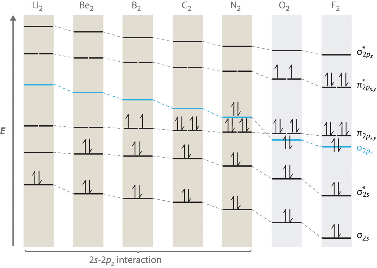
For period 2 diatomic molecules to the left of N2 in the periodic table, a slightly different molecular orbital energy-level diagram is needed because the \( \sigma _{2p_{z}} \) molecular orbital is slightly higher in energy than the degenerate \( \pi ^{\star }_{np_{x}} \) and \( \pi ^{\star }_{np_{y}} \) orbitals. The difference in energy between the 2s and 2p atomic orbitals increases from Li2 to F2 due to increasing nuclear charge and poor screening of the 2s electrons by electrons in the 2p subshell. The bonding interaction between the 2s orbital on one atom and the 2pz orbital on the other is most important when the two orbitals have similar energies. This interaction decreases the energy of the σ2s orbital and increases the energy of the \( \sigma _{2p_{z}} \) orbital. Thus for Li2, Be2, B2, C2, and N2, the \( \sigma _{2p_{z}} \) orbital is higher in energy than the \( \sigma _{3p_{z}} \) orbitals, as shown in Figure 6.5.11 Experimentally, it is found that the energy gap between the ns and np atomic orbitals increases as the nuclear charge increases (Figure 6.5.11 ). Thus for example, the \( \sigma _{2p_{z}} \) molecular orbital is at a lower energy than the \( \pi _{2p_{x,y}} \) pair.
Figure 6.5.11 Molecular Orbital Energy-Level Diagrams for the Diatomic Molecules of the Period 2 Elements
Unlike earlier diagrams, only the molecular orbital energy levels for the molecules are shown here. For simplicity, the atomic orbital energy levels for the component atoms have been omitted. For Li2 through N2, the \( \sigma _{2p_{z}} \) orbital is higher in energy than the \( \pi _{2p_{x,y}} \) orbitals. In contrast, the \( \sigma _{2p_{z}} \) orbital is lower in energy than the \( \pi _{2p_{x,y}} \) orbitals for O2 and F2 due to the increase in the energy difference between the 2s and 2p atomic orbitals as the nuclear charge increases across the row.
Completing the diagram for N2 in the same manner as demonstrated previously, we find that the 10 valence electrons result in 8 bonding electrons and 2 antibonding electrons, for a predicted bond order of 3, a triple bond. Experimental data show that the N–N bond is significantly shorter than the F–F bond (109.8 pm in N2 versus 141.2 pm in F2), and the bond energy is much greater for N2 than for F2 (945.3 kJ/mol versus 158.8 kJ/mol, respectively). Thus the N2 bond is much shorter and stronger than the F2 bond, consistent with what we would expect when comparing a triple bond with a single bond.
Example 13
Use a qualitative molecular orbital energy-level diagram to predict the electron configuration, the bond order, and the number of unpaired electrons in S2, a bright blue gas at high temperatures.
Given: chemical species
Asked for: molecular orbital energy-level diagram, bond order, and number of unpaired electrons
Strategy:
A Write the valence electron configuration of sulfur and determine the type of molecular orbitals formed in S2. Predict the relative energies of the molecular orbitals based on how close in energy the valence atomic orbitals are to one another.
B Draw the molecular orbital energy-level diagram for this system and determine the total number of valence electrons in S2.
C Fill the molecular orbitals in order of increasing energy, being sure to obey the Pauli principle and Hund’s rule.
D Calculate the bond order and describe the bonding.
Solution:
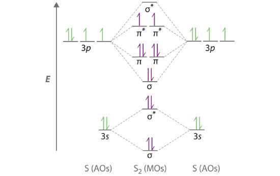
A Sulfur has a [Ne]3s23p4 valence electron configuration. To create a molecular orbital energy-level diagram similar to those in Figure 6.5.9 and Figure 6.5.11 , we need to know how close in energy the 3s and 3p atomic orbitals are because their energy separation will determine whether the \( \pi _{3p_{x,y}} \) or the \( \sigma _{3p_{z}} \)> molecular orbital is higher in energy. Because the ns–np energy gap increases as the nuclear charge increases (Figure 5.3.11 ), the \( \sigma _{3p_{z}} \) molecular orbital will be lower in energy than the \( \pi _{3p_{x,y}} \) pair.
B The molecular orbital energy-level diagram is as follows:
Each sulfur atom contributes 6 valence electrons, for a total of 12 valence electrons.
C Ten valence electrons are used to fill the orbitals through \( \pi _{3p_{x}} \) and \( \pi _{3p_{y}} \), leaving 2 electrons to occupy the degenerate \( \pi ^{\star }_{3p_{x}} \) and \( \pi ^{\star }_{3p_{y}} \) pair. From Hund’s rule, the remaining 2 electrons must occupy these orbitals separately with their spins aligned. With the numbers of electrons written as superscripts, the electron configuration of S2 is \( \left ( \sigma _{3s} \right )^{2}\left ( \sigma ^{\star }_{3s} \right )^{2}\left ( \sigma _{3p_{z}} \right )^{2}\left ( \pi _{3p_{x,y}} \right )^{4}\left ( \pi _{3p ^{\star }_{x,y}} \right )^{2} \) with 2 unpaired electrons. The bond order is (8 − 4) ÷ 2 = 2, so we predict an S=S double bond.
Exercise
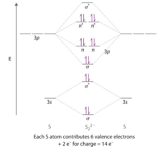
Use a qualitative molecular orbital energy-level diagram to predict the electron configuration, the bond order, and the number of unpaired electrons in the peroxide ion (O22−).
Answer: \( \left ( \sigma _{2s} \right )^{2}\left ( \sigma ^{\star }_{2s} \right )^{2}\left ( \sigma _{2p_{z}} \right )^{2}\left ( \pi _{2p_{x,y}} \right )^{4}\left ( \pi _{2p ^{\star }_{x,y}} \right )^{4} \) bond order of 1; no unpaired electrons
Molecular Orbitals for Heteronuclear Diatomic Molecules
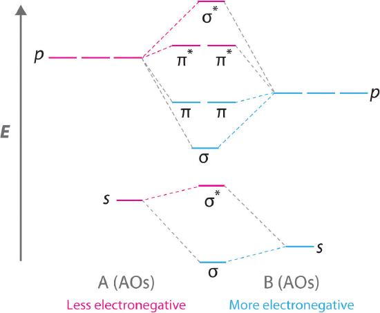
Diatomic molecules with two different atoms are called heteronuclear diatomic molecules A molecule that consists of two atoms of different elements.. When two nonidentical atoms interact to form a chemical bond, the interacting atomic orbitals do not have the same energy. If, for example, element B is more electronegative than element A (χB > χA), the net result is a “skewed” molecular orbital energy-level diagram, such as the one shown for a hypothetical A–B molecule in Figure 6.5.12 . The atomic orbitals of element B are uniformly lower in energy than the corresponding atomic orbitals of element A because of the enhanced stability of the electrons in element B. The molecular orbitals are no longer symmetrical, and the energies of the bonding molecular orbitals are more similar to those of the atomic orbitals of B. Hence the electron density of bonding electrons is likely to be closer to the more electronegative atom. In this way, molecular orbital theory can describe a polar covalent bond.
Figure 6.5.12 Molecular Orbital Energy-Level Diagram for a Heteronuclear Diatomic Molecule AB, Where χB > χA
The bonding molecular orbitals are closer in energy to the atomic orbitals of the more electronegative B atom. Consequently, the electrons in the bonding orbitals are not shared equally between the two atoms. On average, they are closer to the B atom, resulting in a polar covalent bond.
Note the Pattern
A molecular orbital energy-level diagram is always skewed toward the more electronegative atom.
An Odd Number of Valence Electrons: NO
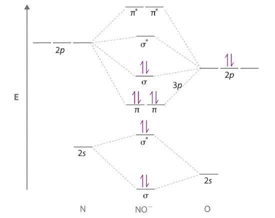
Nitric oxide (NO) is an example of a heteronuclear diatomic molecule. The reaction of O2 with N2 at high temperatures in internal combustion engines forms nitric oxide, which undergoes a complex reaction with O2 to produce NO2, which in turn is responsible for the brown color we associate with air pollution. Recently, however, nitric oxide has also been recognized to be a vital biological messenger involved in regulating blood pressure and long-term memory in mammals.
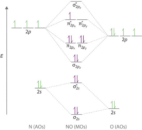
Because NO has an odd number of valence electrons (5 from nitrogen and 6 from oxygen, for a total of 11), its bonding and properties cannot be successfully explained by either the Lewis electron-pair approach or valence bond theory. The molecular orbital energy-level diagram for NO (Figure 6.5.13 ) shows that the general pattern is similar to that for the O2 molecule (see Figure 6.5.11 ). Because 10 electrons are sufficient to fill all the bonding molecular orbitals derived from 2p atomic orbitals, the 11th electron must occupy one of the degenerate π* orbitals. The predicted bond order for NO is therefore (8-3) ÷ 2 = 2 1/2 . Experimental data, showing an N–O bond length of 115 pm and N–O bond energy of 631 kJ/mol, are consistent with this description. These values lie between those of the N2 and O2 molecules, which have triple and double bonds, respectively. As we stated earlier, molecular orbital theory can therefore explain the bonding in molecules with an odd number of electrons, such as NO, whereas Lewis electron structures cannot.
Figure 6.5.13 Molecular Orbital Energy-Level Diagram for NO
Because NO has 11 valence electrons, it is paramagnetic, with a single electron occupying the \( \left ( \pi ^{\star }_{2p_{x}},\; \pi ^{\star }_{2p_{y}} \right ) \) pair of orbitals.
Molecular orbital theory can also tell us something about the chemistry of NO. As indicated in the energy-level diagram in Figure 6.5.13 , NO has a single electron in a relatively high-energy molecular orbital. We might therefore expect it to have similar reactivity as alkali metals such as Li and Na with their single valence electrons. In fact, NO is easily oxidized to the NO+ cation, which is isoelectronic with N2 and has a bond order of 3, corresponding to an N≡O triple bond.
Nonbonding Molecular Orbitals
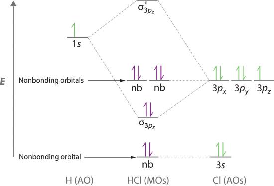
Molecular orbital theory is also able to explain the presence of lone pairs of electrons. Consider, for example, the HCl molecule, whose Lewis electron structure has three lone pairs of electrons on the chlorine atom. Using the molecular orbital approach to describe the bonding in HCl, we can see from Figure 6.3.14 that the 1s orbital of atomic hydrogen is closest in energy to the 3p orbitals of chlorine. Consequently, the filled Cl 3s atomic orbital is not involved in bonding to any appreciable extent, and the only important interactions are those between the H 1s and Cl 3p orbitals. Of the three p orbitals, only one, designated as 3pz, can interact with the H 1s orbital. The 3px and 3py atomic orbitals have no net overlap with the 1s orbital on hydrogen, so they are not involved in bonding. Because the energies of the Cl 3s, 3px, and 3py orbitals do not change when HCl forms, they are called nonbonding molecular orbitals A molecular orbital that forms when atomic orbitals or orbital lobes interact only very weakly, creating essentially no change in the electron probability density between the nuclei.. A nonbonding molecular orbital occupied by a pair of electrons is the molecular orbital equivalent of a lone pair of electrons. By definition, electrons in nonbonding orbitals have no effect on bond order, so they are not counted in the calculation of bond order. Thus the predicted bond order of HCl is (2 − 0) ÷ 2 = 1. Because the σ bonding molecular orbital is closer in energy to the Cl 3pz than to the H 1s atomic orbital, the electrons in the σ orbital are concentrated closer to the chlorine atom than to hydrogen. A molecular orbital approach to bonding can therefore be used to describe the polarization of the H–Cl bond to give \( H^{\delta +} -- Cl^{\delta -} \)
Figure 6.5.14 Molecular Orbital Energy-Level Diagram for HCl
The hydrogen 1s atomic orbital interacts most strongly with the 3pz orbital on chlorine, producing a bonding/antibonding pair of molecular orbitals. The other electrons on Cl are best viewed as nonbonding. As a result, only the bonding σ orbital is occupied by electrons, giving a bond order of 1.
Note the Pattern
Electrons in nonbonding molecular orbitals have no effect on bond order.
Example 14
Use a “skewed” molecular orbital energy-level diagram like the one in Figure 6.5.12 to describe the bonding in the cyanide ion (CN−). What is the bond order?
Given: chemical species
Asked for: “skewed” molecular orbital energy-level diagram, bonding description, and bond order
Strategy:
A Calculate the total number of valence electrons in CN−. Then place these electrons in a molecular orbital energy-level diagram like Figure 6.5.12 in order of increasing energy. Be sure to obey the Pauli principle and Hund’s rule while doing so.
B Calculate the bond order and describe the bonding in CN−.
Solution:
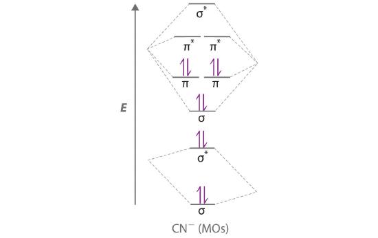
A The CN− ion has a total of 10 valence electrons: 4 from C, 5 from N, and 1 for the −1 charge. Placing these electrons in an energy-level diagram like Figure 6.5.12 fills the five lowest-energy orbitals, as shown here:
Because χN > χC, the atomic orbitals of N (on the right) are lower in energy than those of C. B The resulting valence electron configuration gives a predicted bond order of (8 − 2) ÷ 2 = 3, indicating that the CN− ion has a triple bond, analogous to that in N2.
Exercise
Use a qualitative molecular orbital energy-level diagram to describe the bonding in the hypochlorite ion (OCl−). What is the bond order?
Answer: All molecular orbitals except the highest-energy σ* are filled, giving a bond order of 1.
Although the molecular orbital approach reveals a great deal about the bonding in a given molecule, the procedure quickly becomes computationally intensive for molecules of even moderate complexity. Furthermore, because the computed molecular orbitals extend over the entire molecule, they are often difficult to represent in a way that is easy to visualize. Therefore we do not use a pure molecular orbital approach to describe the bonding in molecules or ions with more than two atoms. Instead, we use a valence bond approach and a molecular orbital approach to explain, among other things, the concept of resonance, which cannot adequately be explained using other methods.
Summary
A molecular orbital (MO) is an allowed spatial distribution of electrons in a molecule that is associated with a particular orbital energy. Unlike an atomic orbital (AO), which is centered on a single atom, a molecular orbital extends over all the atoms in a molecule or ion. Hence the molecular orbital theory of bonding is a delocalized approach. Molecular orbitals are constructed using linear combinations of atomic orbitals (LCAOs), which are usually the mathematical sums and differences of wave functions that describe overlapping atomic orbitals. Atomic orbitals interact to form three types of molecular orbitals.
- Orbitals or orbital lobes with the same sign interact to give increased electron probability along the plane of the internuclear axis because of constructive reinforcement of the wave functions. Consequently, electrons in such molecular orbitals help to hold the positively charged nuclei together. Such orbitals are bonding molecular orbitals, and they are always lower in energy than the parent atomic orbitals.
- Orbitals or orbital lobes with opposite signs interact to give decreased electron probability density between the nuclei because of destructive interference of the wave functions. Consequently, electrons in such molecular orbitals are primarily located outside the internuclear region, leading to increased repulsions between the positively charged nuclei. These orbitals are called antibonding molecular orbitals, and they are always higher in energy than the parent atomic orbitals.
- Some atomic orbitals interact only very weakly, and the resulting molecular orbitals give essentially no change in the electron probability density between the nuclei. Hence electrons in such orbitals have no effect on the bonding in a molecule or ion. These orbitals are nonbonding molecular orbitals, and they have approximately the same energy as the parent atomic orbitals.
A completely bonding molecular orbital contains no nodes (regions of zero electron probability) perpendicular to the internuclear axis, whereas a completely antibonding molecular orbital contains at least one node perpendicular to the internuclear axis. A sigma (σ) orbital (bonding) or a sigma star (σ*) orbital (antibonding) is symmetrical about the internuclear axis. Hence all cross-sections perpendicular to that axis are circular. Both a pi (π) orbital (bonding) and a pi star (π*) orbital (antibonding) possess a nodal plane that contains the nuclei, with electron density localized on both sides of the plane.
The energies of the molecular orbitals versus those of the parent atomic orbitals can be shown schematically in an energy-level diagram. The electron configuration of a molecule is shown by placing the correct number of electrons in the appropriate energy-level diagram, starting with the lowest-energy orbital and obeying the Pauli principle; that is, placing only two electrons with opposite spin in each orbital. From the completed energy-level diagram, we can calculate the bond order, defined as one-half the net number of bonding electrons. In bond orders, electrons in antibonding molecular orbitals cancel electrons in bonding molecular orbitals, while electrons in nonbonding orbitals have no effect and are not counted. Bond orders of 1, 2, and 3 correspond to single, double, and triple bonds, respectively. Molecules with predicted bond orders of 0 are generally less stable than the isolated atoms and do not normally exist.
Molecular orbital energy-level diagrams for diatomic molecules can be created if the electron configuration of the parent atoms is known, following a few simple rules. Most important, the number of molecular orbitals in a molecule is the same as the number of atomic orbitals that interact. The difference between bonding and antibonding molecular orbital combinations is proportional to the overlap of the parent orbitals and decreases as the energy difference between the parent atomic orbitals increases. With such an approach, the electronic structures of virtually all commonly encountered homonuclear diatomic molecules, molecules with two identical atoms, can be understood. The molecular orbital approach correctly predicts that the O2 molecule has two unpaired electrons and hence is attracted into a magnetic field. In contrast, most substances have only paired electrons. A similar procedure can be applied to molecules with two dissimilar atoms, called heteronuclear diatomic molecules, using a molecular orbital energy-level diagram that is skewed or tilted toward the more electronegative element. Molecular orbital theory is able to describe the bonding in a molecule with an odd number of electrons such as NO and even to predict something about its chemistry.
Key Takeaway
- Molecular orbital theory, a delocalized approach to bonding, can often explain a compound’s color, why a compound with unpaired electrons is stable, semiconductor behavior, and resonance, none of which can be explained using a localized approach.
Conceptual Problems
-
What is the distinction between an atomic orbital and a molecular orbital? How many electrons can a molecular orbital accommodate?
-
Why is the molecular orbital approach to bonding called a delocalized approach?
-
How is the energy of an electron affected by interacting with more than one positively charged atomic nucleus at a time? Does the energy of the system increase, decrease, or remain unchanged? Why?
-
Constructive and destructive interference of waves can be used to understand how bonding and antibonding molecular orbitals are formed from atomic orbitals. Does constructive interference of waves result in increased or decreased electron probability density between the nuclei? Is the result of constructive interference best described as a bonding molecular orbital or an antibonding molecular orbital?
-
What is a “node” in molecular orbital theory? How is it similar to the nodes found in atomic orbitals?
-
What is the difference between an s orbital and a σ orbital? How are the two similar?
-
Why is a σ1s molecular orbital lower in energy than the two s atomic orbitals from which it is derived? Why is a σ*1s molecular orbital higher in energy than the two s atomic orbitals from which it is derived?
-
What is meant by the term bond order in molecular orbital theory? How is the bond order determined from molecular orbital theory different from the bond order obtained using Lewis electron structures? How is it similar?
-
What is the effect of placing an electron in an antibonding orbital on the bond order, the stability of the molecule, and the reactivity of a molecule?
-
How can the molecular orbital approach to bonding be used to predict a molecule’s stability? What advantages does this method have over the Lewis electron-pair approach to bonding?
-
What is the relationship between bond length and bond order? What effect do antibonding electrons have on bond length? on bond strength?
-
Draw a diagram that illustrates how atomic p orbitals can form both σ and π molecular orbitals. Which type of molecular orbital typically results in a stronger bond?
-
What is the minimum number of nodes in σ, π, σ*, and π*? How are the nodes in bonding orbitals different from the nodes in antibonding orbitals?
-
It is possible to form both σ and π molecular orbitals with the overlap of a d orbital with a p orbital, yet it is possible to form only σ molecular orbitals between s and d orbitals. Illustrate why this is so with a diagram showing the three types of overlap between this set of orbitals. Include a fourth image that shows why s and d orbitals cannot combine to form a π molecular orbital.
-
Is it possible for an npx orbital on one atom to interact with an npy orbital on another atom to produce molecular orbitals? Why or why not? Can the same be said of npy and npz orbitals on adjacent atoms?
-
What is meant by degenerate orbitals in molecular orbital theory? Is it possible for σ molecular orbitals to form a degenerate pair? Explain your answer.
-
Why are bonding molecular orbitals lower in energy than the parent atomic orbitals? Why are antibonding molecular orbitals higher in energy than the parent atomic orbitals?
-
What is meant by the law of conservation of orbitals?
-
Atomic orbitals on different atoms have different energies. When atomic orbitals from nonidentical atoms are combined to form molecular orbitals, what is the effect of this difference in energy on the resulting molecular orbitals?
-
If two atomic orbitals have different energies, how does this affect the orbital overlap and the molecular orbitals formed by combining the atomic orbitals?
-
Are the Al–Cl bonds in AlCl3 stronger, the same strength, or weaker than the Al–Br bonds in AlBr3? Why?
-
Are the Ga–Cl bonds in GaCl3 stronger, the same strength, or weaker than the Sb–Cl bonds in SbCl3? Why?
-
What is meant by a nonbonding molecular orbital, and how is it formed? How does the energy of a nonbonding orbital compare with the energy of bonding or antibonding molecular orbitals derived from the same atomic orbitals?
-
Many features of molecular orbital theory have analogs in Lewis electron structures. How do Lewis electron structures represent
- nonbonding electrons?
- electrons in bonding molecular orbitals?
-
How does electron screening affect the energy difference between the 2s and 2p atomic orbitals of the period 2 elements? How does the energy difference between the 2s and 2p atomic orbitals depend on the effective nuclear charge?
-
For σ versus π, π versus σ*, and σ* versus π*, which of the resulting molecular orbitals is lower in energy?
-
The energy of a σ molecular orbital is usually lower than the energy of a π molecular orbital derived from the same set of atomic orbitals. Under specific conditions, however, the order can be reversed. What causes this reversal? In which portion of the periodic table is this kind of orbital energy reversal most likely to be observed?
-
Is the \( \sigma _{2p_{z}} \) molecular orbital stabilized or destabilized by interaction with the σ2s molecular orbital in N2? in O2? In which molecule is this interaction most important?
-
Explain how the Lewis electron-pair approach and molecular orbital theory differ in their treatment of bonding in O2.
-
Why is it crucial to our existence that O2 is paramagnetic?
-
Will NO or CO react more quickly with O2? Explain your answer.
-
How is the energy-level diagram of a heteronuclear diatomic molecule, such as CO, different from that of a homonuclear diatomic molecule, such as N2?
-
How does molecular orbital theory describe the existence of polar bonds? How is this apparent in the molecular orbital diagram of HCl?
Answers
-
An atomic orbital is a region of space around an atom that has a non-zero probability for an electron with a particular energy. Analogously, a molecular orbital is a region of space in a molecule that has a non-zero probability for an electron with a particular energy. Both an atomic orbital and a molecular orbital can contain two electrons.
-
-
-
-
-
-
-
-
-
-
-
-
-
-
No. Because an npx orbital on one atom is perpendicular to an npy orbital on an adjacent atom, the net overlap between the two is zero. This is also true for npy and npz orbitals on adjacent atoms.
-
-
-
-
-
-
-
-
-
-
-
-
-
-
-
-
-
-
Numerical Problems
-
Use a qualitative molecular orbital energy-level diagram to describe the bonding in S22−. What is the bond order? How many unpaired electrons does it have?
-
Use a qualitative molecular orbital energy-level diagram to describe the bonding in F22+. What is the bond order? How many unpaired electrons does it have?
-
If three atomic orbitals combine to form molecular orbitals, how many molecular orbitals are generated? How many molecular orbitals result from the combination of four atomic orbitals? From five?
-
If two atoms interact to form a bond, and each atom has four atomic orbitals, how many molecular orbitals will form?
-
Sketch the possible ways of combining two 1s orbitals on adjacent atoms. How many molecular orbitals can be formed by this combination? Be sure to indicate any nodal planes.
-
Sketch the four possible ways of combining two 2p orbitals on adjacent atoms. How many molecular orbitals can be formed by this combination? Be sure to indicate any nodal planes.
-
If a diatomic molecule has a bond order of 2 and six bonding electrons, how many antibonding electrons must it have? What would be the corresponding Lewis electron structure (disregarding lone pairs)? What would be the effect of a one-electron reduction on the bond distance?
-
What is the bond order of a diatomic molecule with six bonding electrons and no antibonding electrons? If an analogous diatomic molecule has six bonding electrons and four antibonding electrons, which has the stronger bond? the shorter bond distance? If the highest occupied molecular orbital in both molecules is bonding, how will a one-electron oxidation affect the bond length?
-
Qualitatively discuss how the bond distance in a diatomic molecule would be affected by adding an electron to
- an antibonding orbital.
- a bonding orbital.
-
Explain why the oxidation of O2 decreases the bond distance, whereas the oxidation of N2 increases the N–N distance. Could Lewis electron structures be employed to answer this problem?
-
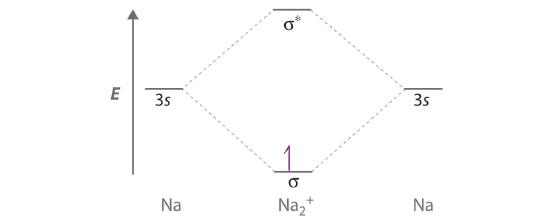
Draw a molecular orbital energy-level diagram for Na2+. What is the bond order in this ion? Is this ion likely to be a stable species? If not, would you recommend an oxidation or a reduction to improve stability? Explain your answer. Based on your answers, will Na2+, Na2, or Na2− be the most stable? Why?
-
Draw a molecular orbital energy-level diagram for Xe2+, showing only the valence orbitals and electrons. What is the bond order in this ion? Is this ion likely to be a stable species? If not, would you recommend an oxidation or a reduction to improve stability? Explain your answer. Based on your answers, will Xe22+, Xe2+, or Xe2 be most stable? Why?
-
Draw a molecular orbital energy-level diagram for O22− and predict its valence electron configuration, bond order, and stability.
-
Draw a molecular orbital energy-level diagram for C22– and predict its valence electron configuration, bond order, and stability.
-
If all the p orbitals in the valence shells of two atoms interact, how many molecular orbitals are formed? Why is it not possible to form three π orbitals (and the corresponding antibonding orbitals) from the set of six p orbitals?
-
Draw a complete energy-level diagram for B2. Determine the bond order and whether the molecule is paramagnetic or diamagnetic. Explain your rationale for the order of the molecular orbitals.
-
Sketch a molecular orbital energy-level diagram for each ion. Based on your diagram, what is the bond order of each species?
- NO+
- NO−
-
The diatomic molecule BN has never been detected. Assume that its molecular orbital diagram would be similar to that shown for CN− in Section 5.3 "Delocalized Bonding and Molecular Orbitals" but that the <( \sigma _{2p_{z}} \) molecular orbital is higher in energy than the \( \pi _{2p_{x,y}} \) molecular orbitals.
- Sketch a molecular orbital diagram for BN.
- Based on your diagram, what would be the bond order of this molecule?
- Would you expect BN to be stable? Why or why not?
-
Of the species BN, CO, C2, and N2, which are isoelectronic?
-
Of the species CN−, NO+, B22−, and O2+, which are isoelectronic?
Answers
-
-
The number of molecular orbitals is always equal to the number of atomic orbitals you start with. Thus, combining three atomic orbitals gives three molecular orbitals, and combining four or five atomic orbitals will give four or five molecular orbitals, respectively.
-
-
-
-
-
- Adding an electron to an antibonding molecular orbital will decrease the bond order, thereby increasing the bond distance.
- Adding an electron to a bonding molecular orbital will increase the bond order, thereby decreasing the bond distance.
-
-
Sodium contains only a single valence electron in its 3s atomic orbital. Combining two 3s atomic orbitals gives two molecular orbitals; as shown in the diagram, these are a σ (bonding) orbital and a σ* (antibonding) orbital.
Although each sodium atom contributes one valence electron, the +1 charge indicates that one electron has been removed. Placing the single electron in the lowest energy molecular orbital gives a \( \sigma ^{1}_{3s} \) electronic configuration and a bond order of 0.5. Consequently, Na2+ should be a stable species. Oxidizing Na2+ by one electron to give Na22+ would remove the electron in the σ3s molecular orbital, giving a bond order of 0. Conversely, reducing Na2+ by one electron to give Na2 would put an additional electron into the σ3s molecular orbital, giving a bond order of 1. Thus, reduction to Na2 would produce a more stable species than oxidation to Na22+. The Na2− ion would have two electrons in the bonding σ3s molecular orbital and one electron in the σ3s* antibonding molecular orbital, giving a bond order of 0.5. Thus, Na2 is the most stable of the three species.
-
-
-
-
-
-
- The NO+ ion has 10 valence electrons, which fill all the molecular orbitals up to and including the σ2p. With eight electrons in bonding molecular orbitals and two electrons in antibonding orbitals, the bond order in NO+ is (8 − 2)/2 = 3.
- The NO− ion contains two more electrons, which fill the \( \sigma ^{\star }_{2p} \) molecular orbital. The bond order in NO− is (8 − 4)/2 = 2.
-
-
BN and C2 are isoelectronic, with 12 valence electrons, while N2 and CO are isoelectronic, with 14 valence electrons.
-
Contributors
- Anonymous
Modified by Joshua Halpern
Paramagnetism of O2 Video by Harvard Natural Sciences Lecture Demos on YouTube


