17.2: Electrochemical Cells
- Page ID
- 151768
\( \newcommand{\vecs}[1]{\overset { \scriptstyle \rightharpoonup} {\mathbf{#1}} } \)
\( \newcommand{\vecd}[1]{\overset{-\!-\!\rightharpoonup}{\vphantom{a}\smash {#1}}} \)
\( \newcommand{\id}{\mathrm{id}}\) \( \newcommand{\Span}{\mathrm{span}}\)
( \newcommand{\kernel}{\mathrm{null}\,}\) \( \newcommand{\range}{\mathrm{range}\,}\)
\( \newcommand{\RealPart}{\mathrm{Re}}\) \( \newcommand{\ImaginaryPart}{\mathrm{Im}}\)
\( \newcommand{\Argument}{\mathrm{Arg}}\) \( \newcommand{\norm}[1]{\| #1 \|}\)
\( \newcommand{\inner}[2]{\langle #1, #2 \rangle}\)
\( \newcommand{\Span}{\mathrm{span}}\)
\( \newcommand{\id}{\mathrm{id}}\)
\( \newcommand{\Span}{\mathrm{span}}\)
\( \newcommand{\kernel}{\mathrm{null}\,}\)
\( \newcommand{\range}{\mathrm{range}\,}\)
\( \newcommand{\RealPart}{\mathrm{Re}}\)
\( \newcommand{\ImaginaryPart}{\mathrm{Im}}\)
\( \newcommand{\Argument}{\mathrm{Arg}}\)
\( \newcommand{\norm}[1]{\| #1 \|}\)
\( \newcommand{\inner}[2]{\langle #1, #2 \rangle}\)
\( \newcommand{\Span}{\mathrm{span}}\) \( \newcommand{\AA}{\unicode[.8,0]{x212B}}\)
\( \newcommand{\vectorA}[1]{\vec{#1}} % arrow\)
\( \newcommand{\vectorAt}[1]{\vec{\text{#1}}} % arrow\)
\( \newcommand{\vectorB}[1]{\overset { \scriptstyle \rightharpoonup} {\mathbf{#1}} } \)
\( \newcommand{\vectorC}[1]{\textbf{#1}} \)
\( \newcommand{\vectorD}[1]{\overrightarrow{#1}} \)
\( \newcommand{\vectorDt}[1]{\overrightarrow{\text{#1}}} \)
\( \newcommand{\vectE}[1]{\overset{-\!-\!\rightharpoonup}{\vphantom{a}\smash{\mathbf {#1}}}} \)
\( \newcommand{\vecs}[1]{\overset { \scriptstyle \rightharpoonup} {\mathbf{#1}} } \)
\( \newcommand{\vecd}[1]{\overset{-\!-\!\rightharpoonup}{\vphantom{a}\smash {#1}}} \)
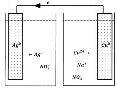
\(\newcommand{\avec}{\mathbf a}\) \(\newcommand{\bvec}{\mathbf b}\) \(\newcommand{\cvec}{\mathbf c}\) \(\newcommand{\dvec}{\mathbf d}\) \(\newcommand{\dtil}{\widetilde{\mathbf d}}\) \(\newcommand{\evec}{\mathbf e}\) \(\newcommand{\fvec}{\mathbf f}\) \(\newcommand{\nvec}{\mathbf n}\) \(\newcommand{\pvec}{\mathbf p}\) \(\newcommand{\qvec}{\mathbf q}\) \(\newcommand{\svec}{\mathbf s}\) \(\newcommand{\tvec}{\mathbf t}\) \(\newcommand{\uvec}{\mathbf u}\) \(\newcommand{\vvec}{\mathbf v}\) \(\newcommand{\wvec}{\mathbf w}\) \(\newcommand{\xvec}{\mathbf x}\) \(\newcommand{\yvec}{\mathbf y}\) \(\newcommand{\zvec}{\mathbf z}\) \(\newcommand{\rvec}{\mathbf r}\) \(\newcommand{\mvec}{\mathbf m}\) \(\newcommand{\zerovec}{\mathbf 0}\) \(\newcommand{\onevec}{\mathbf 1}\) \(\newcommand{\real}{\mathbb R}\) \(\newcommand{\twovec}[2]{\left[\begin{array}{r}#1 \\ #2 \end{array}\right]}\) \(\newcommand{\ctwovec}[2]{\left[\begin{array}{c}#1 \\ #2 \end{array}\right]}\) \(\newcommand{\threevec}[3]{\left[\begin{array}{r}#1 \\ #2 \\ #3 \end{array}\right]}\) \(\newcommand{\cthreevec}[3]{\left[\begin{array}{c}#1 \\ #2 \\ #3 \end{array}\right]}\) \(\newcommand{\fourvec}[4]{\left[\begin{array}{r}#1 \\ #2 \\ #3 \\ #4 \end{array}\right]}\) \(\newcommand{\cfourvec}[4]{\left[\begin{array}{c}#1 \\ #2 \\ #3 \\ #4 \end{array}\right]}\) \(\newcommand{\fivevec}[5]{\left[\begin{array}{r}#1 \\ #2 \\ #3 \\ #4 \\ #5 \\ \end{array}\right]}\) \(\newcommand{\cfivevec}[5]{\left[\begin{array}{c}#1 \\ #2 \\ #3 \\ #4 \\ #5 \\ \end{array}\right]}\) \(\newcommand{\mattwo}[4]{\left[\begin{array}{rr}#1 \amp #2 \\ #3 \amp #4 \\ \end{array}\right]}\) \(\newcommand{\laspan}[1]{\text{Span}\{#1\}}\) \(\newcommand{\bcal}{\cal B}\) \(\newcommand{\ccal}{\cal C}\) \(\newcommand{\scal}{\cal S}\) \(\newcommand{\wcal}{\cal W}\) \(\newcommand{\ecal}{\cal E}\) \(\newcommand{\coords}[2]{\left\{#1\right\}_{#2}}\) \(\newcommand{\gray}[1]{\color{gray}{#1}}\) \(\newcommand{\lgray}[1]{\color{lightgray}{#1}}\) \(\newcommand{\rank}{\operatorname{rank}}\) \(\newcommand{\row}{\text{Row}}\) \(\newcommand{\col}{\text{Col}}\) \(\renewcommand{\row}{\text{Row}}\) \(\newcommand{\nul}{\text{Nul}}\) \(\newcommand{\var}{\text{Var}}\) \(\newcommand{\corr}{\text{corr}}\) \(\newcommand{\len}[1]{\left|#1\right|}\) \(\newcommand{\bbar}{\overline{\bvec}}\) \(\newcommand{\bhat}{\widehat{\bvec}}\) \(\newcommand{\bperp}{\bvec^\perp}\) \(\newcommand{\xhat}{\widehat{\xvec}}\) \(\newcommand{\vhat}{\widehat{\vvec}}\) \(\newcommand{\uhat}{\widehat{\uvec}}\) \(\newcommand{\what}{\widehat{\wvec}}\) \(\newcommand{\Sighat}{\widehat{\Sigma}}\) \(\newcommand{\lt}{<}\) \(\newcommand{\gt}{>}\) \(\newcommand{\amp}{&}\) \(\definecolor{fillinmathshade}{gray}{0.9}\)We can extend the idea of carrying out the electron loss and electron gain steps in different physical locations. Suppose that the only aqueous species in contact with the silver metal are silver ions and nitrate ions; the silver metal is also in contact with a length of copper wire, whose other end dips into a separate reservoir containing an aqueous solution of sodium nitrate. This arrangement is sketched in Figure 1. When we create this arrangement, nothing happens. We do not see any visible change in the silver metal, and the water contacting the copper wire never turns blue. On the one hand, this result does not surprise us. We are accustomed to the idea that reactants must be able to contact one another in order for reaction to occur.

On the other hand, the original experiment really does show that silver ions can accept electrons in one location while copper atoms give them up in another, so long as we provide a metal bridge on which the electrons can move between the two locations. Why should this not continue to happen in the new experimental arrangement? In fact, it does. It is just that the reaction occurs to only a very small extent before stopping altogether. The reason is easy to appreciate. After a very small number of silver ions are reduced, the silver nitrate solution contains more nitrate ions than silver ions; the solution as a whole has a negative charge. In the other reservoir, a small number of cupric ions dissolve, but there is no increase in the number of counter ions, so this solution acquires a positive charge. These net charges polarize the metal that connects them; the metal has an excess of positive charge at the copper-solution end and an excess of negative charge at the silver-solution end. This polarization opposes the motion of a negatively charged electron from the copper-solution end toward the silver-solution end. When the polarization becomes sufficiently great, electron flow ceases and no further reaction can occur.
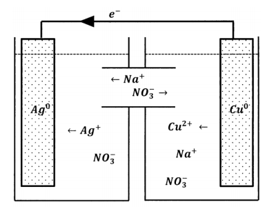
By this analysis, the anions that the cupric solution needs in order to achieve electroneutrality are present in the silver-ion solution. The reaction stops because the anions have no way to get from one solution to the other. Evidently, the way to make the reaction proceed is to modify the two-reservoir experiment so that nitrate ions can move from the silver-solution reservoir to the copper-solution reservoir. Alternatively, we could introduce a modification that allows copper ions to move in the opposite direction or one that allows both kinds of movement. We can achieve the latter by connecting the two solutions with a tube containing sodium nitrate solution, as diagrammed in Figure 2. Now, nitrate ions can move between the reservoirs and maintain electroneutrality in both of them. However, silver ions can also move between the reservoirs. When we do this experiment, we observe that electrons do flow through the wire, indicating that silver-ion reduction and copper-atom oxidation are occurring at the separated sites. However, after a short time, the solutions mix; silver ions migrate through the aqueous medium and react directly with the copper metal. Because the mixing is poorly controllable, the reproducibility of this experiment is poor.

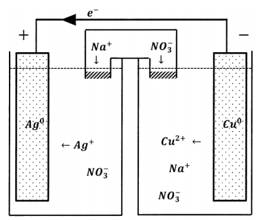
Evidently, we need a way to permit the exchange of ions between the two reservoirs that does not permit the wholesale transfer of reactive species. One device that accomplishes this is called a salt bridge. The requirement we face is that ions should be able to migrate from reservoir to reservoir so as to maintain electroneutrality. However, we do not want ions that participate in electrode reactions to migrate. A salt bridge is simply a salt solution that we use to connect the two reservoirs. To avoid introducing unwanted ions into the reservoir solutions, we prepare the salt-bridge solution using a salt whose ions are not readily oxidized or reduced. Alkali metal salts with nitrate, perchlorate, or halide anions are often used. To avoid mixing the reservoir solutions with the salt bridge solution, we plug each end of the salt bridge with a porous material that permits diffusion of ions but inhibits bulk movement of solution in or out of the bridge. The inhibition of bulk movement can be made much more effective by filling the bridge with a gel, so that the solution is unable to undergo bulk motion in any part of the bridge.
With a salt bridge in place, inert ions can move from one reservoir to the other to maintain electroneutrality. Under these conditions, we see an electrical current through the external circuit and a compensating diffusion of ions through the salt bridge. The salt bridge completes the circuit. Transport of electrons from one electrode to the other carries charge in one direction; motion of ionic species through the salt bridge carries negative charge through the solution in the opposite direction. This compensating ionic motion has anions moving opposite to the electron motion and cations moving in the same direction as the electrons.

We have just described one kind of electrochemical cell. As diagrammed in Figure 3, it has four principal features: two reservoirs within which reactions can occur, a wire through which electrons can pass from one reservoir to the other, and a salt bridge through which ionic species can pass. Many similar electrochemical cells can be constructed. The reservoirs can contain a wide variety of reagents. Because each reservoir must be able to exchange electrons with the connecting wire, each must contain an electrically conducting solid that serves as a terminal and a current collector, and often participates in the chemical change as a reactant or as a catalyst. The combination of reagents and current collector is called a half-cell. The current collector itself is called an electrode, although this term is often applied to the whole half-cell as well. In this case, the wire is the external circuit. In applications of chemical interest, the external circuit typically contains devices to measure the electrochemical cell’s properties as a circuit element.
If we view this electrochemical cell as a device for producing an electrical current, we see that it has a number of practical limitations. Two of the most important relate to the performance of the salt bridge. Whenever electrons move through the external circuit, the salt bridge must accept a charge-compensating number of ions from one reservoir and release the same quantity of ionic charge to the other reservoir. We construct the salt bridge so that ions can pass into and out of it only by diffusion. Consequently, the rate at which ions can diffuse through the salt bridge limits the rate at which electrons can flow through the external circuit. Since diffusion is a slow process over the macroscopic dimensions of the bridge, the cell can pass only a small current. From an electrical perspective, slow diffusion of ions through the salt bridge causes a surplus of positively charged species to develop at one end of the salt bridge and a surplus of negatively charged species to develop at the other. This charge imbalance means that there is a potential gradient across the salt bridge, whose effect is to oppose the flow of further current.
The second limitation of the cell attributable to the properties of the salt bridge is that the amount of current the cell can produce before its performance characteristics change dramatically is limited by the amount of inert salt in the bridge. After a relatively small charge passes through the cell, migration of reactive species from one reservoir to the other becomes significant. Effective electrochemical power sources must use other methods to separate reactants and products while allowing for the transport of ions between half-cells.
Despite these limitations, such electrochemical cells are very effective tools for the study of the thermodynamics of electrochemical reactions. The principle interaction between electrochemistry and thermodynamics revolves around the relationship between the free energy change for the reaction and the properties of the electrochemical cell viewed as a circuit element. In Section 17.14, we see that the Gibbs free energy change for the chemical reaction is proportional to the electrical potential that develops across the terminals of the corresponding electrochemical cell.
In experiments, we find that the electrical potential difference across a cell depends on the amount of current that is being drawn from the cell. Because the movement of ions and other substances within the cell is slow compared to the rate at which a wire can transfer electrons from one terminal to another, potential differences that develop within an operating cell decrease the electrical potential across the terminals. Only when the current being drawn from the cell is zero does the electrical potential correspond precisely to the Gibbs free energy change of the chemical reaction occurring in the cell. This should not surprise us. The experimental measurement of any entropy-dependent thermodynamic function must be made on a system that is undergoing reversible change. A reversible change in an electrochemical cell is a change in which the current flow is zero.
Measuring the electrical potential at zero current is experimentally straightforward, at least in principle. We connect the cell to some reference device that provides a known and variable electrical potential. The connection is made such that the electrical potential from the reference device opposes the potential from the electrochemical cell; that is, we connect the positive terminal of the reference device to the positive terminal of the cell, and the negative terminal of the device to the negative terminal of the cell. (See Section 17.7.) We then vary the potential of the reference device until current flow in the circuit stops. When this occurs the potential drop being supplied by the reference device must be precisely equal to the potential drop across the electrochemical cell, which is the datum we want.
In practice, the reference device is another “standard” electrochemical cell, whose potential drop is defined to have a particular value at specified conditions. Modern electronics make it possible to do the actual measurements with great sophistication. The necessary measurements can also be done with very basic equipment. The principles remain the same. In the basic experiment, a variable resistor is used to adjust the potential drop across the standard cell until it exactly matches that of the cell being studied. When this potential is reached, current flow ceases. Current flow is monitored using a sensitive galvanometer. It is not necessary to actually measure the current. Since we are interested in locating the potential drop at which the current flow is zero, it is sufficient to find the potential drop at which the galvanometer detects no current. The accuracy of the potential measurement depends on the stability of the standard cell potential, the accuracy of the variable resistor, and the sensitivity of the galvanometer.


