17.7: The Direction of Electron Flow and its Implications
- Page ID
- 151772
\( \newcommand{\vecs}[1]{\overset { \scriptstyle \rightharpoonup} {\mathbf{#1}} } \)
\( \newcommand{\vecd}[1]{\overset{-\!-\!\rightharpoonup}{\vphantom{a}\smash {#1}}} \)
\( \newcommand{\id}{\mathrm{id}}\) \( \newcommand{\Span}{\mathrm{span}}\)
( \newcommand{\kernel}{\mathrm{null}\,}\) \( \newcommand{\range}{\mathrm{range}\,}\)
\( \newcommand{\RealPart}{\mathrm{Re}}\) \( \newcommand{\ImaginaryPart}{\mathrm{Im}}\)
\( \newcommand{\Argument}{\mathrm{Arg}}\) \( \newcommand{\norm}[1]{\| #1 \|}\)
\( \newcommand{\inner}[2]{\langle #1, #2 \rangle}\)
\( \newcommand{\Span}{\mathrm{span}}\)
\( \newcommand{\id}{\mathrm{id}}\)
\( \newcommand{\Span}{\mathrm{span}}\)
\( \newcommand{\kernel}{\mathrm{null}\,}\)
\( \newcommand{\range}{\mathrm{range}\,}\)
\( \newcommand{\RealPart}{\mathrm{Re}}\)
\( \newcommand{\ImaginaryPart}{\mathrm{Im}}\)
\( \newcommand{\Argument}{\mathrm{Arg}}\)
\( \newcommand{\norm}[1]{\| #1 \|}\)
\( \newcommand{\inner}[2]{\langle #1, #2 \rangle}\)
\( \newcommand{\Span}{\mathrm{span}}\) \( \newcommand{\AA}{\unicode[.8,0]{x212B}}\)
\( \newcommand{\vectorA}[1]{\vec{#1}} % arrow\)
\( \newcommand{\vectorAt}[1]{\vec{\text{#1}}} % arrow\)
\( \newcommand{\vectorB}[1]{\overset { \scriptstyle \rightharpoonup} {\mathbf{#1}} } \)
\( \newcommand{\vectorC}[1]{\textbf{#1}} \)
\( \newcommand{\vectorD}[1]{\overrightarrow{#1}} \)
\( \newcommand{\vectorDt}[1]{\overrightarrow{\text{#1}}} \)
\( \newcommand{\vectE}[1]{\overset{-\!-\!\rightharpoonup}{\vphantom{a}\smash{\mathbf {#1}}}} \)
\( \newcommand{\vecs}[1]{\overset { \scriptstyle \rightharpoonup} {\mathbf{#1}} } \)
\( \newcommand{\vecd}[1]{\overset{-\!-\!\rightharpoonup}{\vphantom{a}\smash {#1}}} \)
\(\newcommand{\avec}{\mathbf a}\) \(\newcommand{\bvec}{\mathbf b}\) \(\newcommand{\cvec}{\mathbf c}\) \(\newcommand{\dvec}{\mathbf d}\) \(\newcommand{\dtil}{\widetilde{\mathbf d}}\) \(\newcommand{\evec}{\mathbf e}\) \(\newcommand{\fvec}{\mathbf f}\) \(\newcommand{\nvec}{\mathbf n}\) \(\newcommand{\pvec}{\mathbf p}\) \(\newcommand{\qvec}{\mathbf q}\) \(\newcommand{\svec}{\mathbf s}\) \(\newcommand{\tvec}{\mathbf t}\) \(\newcommand{\uvec}{\mathbf u}\) \(\newcommand{\vvec}{\mathbf v}\) \(\newcommand{\wvec}{\mathbf w}\) \(\newcommand{\xvec}{\mathbf x}\) \(\newcommand{\yvec}{\mathbf y}\) \(\newcommand{\zvec}{\mathbf z}\) \(\newcommand{\rvec}{\mathbf r}\) \(\newcommand{\mvec}{\mathbf m}\) \(\newcommand{\zerovec}{\mathbf 0}\) \(\newcommand{\onevec}{\mathbf 1}\) \(\newcommand{\real}{\mathbb R}\) \(\newcommand{\twovec}[2]{\left[\begin{array}{r}#1 \\ #2 \end{array}\right]}\) \(\newcommand{\ctwovec}[2]{\left[\begin{array}{c}#1 \\ #2 \end{array}\right]}\) \(\newcommand{\threevec}[3]{\left[\begin{array}{r}#1 \\ #2 \\ #3 \end{array}\right]}\) \(\newcommand{\cthreevec}[3]{\left[\begin{array}{c}#1 \\ #2 \\ #3 \end{array}\right]}\) \(\newcommand{\fourvec}[4]{\left[\begin{array}{r}#1 \\ #2 \\ #3 \\ #4 \end{array}\right]}\) \(\newcommand{\cfourvec}[4]{\left[\begin{array}{c}#1 \\ #2 \\ #3 \\ #4 \end{array}\right]}\) \(\newcommand{\fivevec}[5]{\left[\begin{array}{r}#1 \\ #2 \\ #3 \\ #4 \\ #5 \\ \end{array}\right]}\) \(\newcommand{\cfivevec}[5]{\left[\begin{array}{c}#1 \\ #2 \\ #3 \\ #4 \\ #5 \\ \end{array}\right]}\) \(\newcommand{\mattwo}[4]{\left[\begin{array}{rr}#1 \amp #2 \\ #3 \amp #4 \\ \end{array}\right]}\) \(\newcommand{\laspan}[1]{\text{Span}\{#1\}}\) \(\newcommand{\bcal}{\cal B}\) \(\newcommand{\ccal}{\cal C}\) \(\newcommand{\scal}{\cal S}\) \(\newcommand{\wcal}{\cal W}\) \(\newcommand{\ecal}{\cal E}\) \(\newcommand{\coords}[2]{\left\{#1\right\}_{#2}}\) \(\newcommand{\gray}[1]{\color{gray}{#1}}\) \(\newcommand{\lgray}[1]{\color{lightgray}{#1}}\) \(\newcommand{\rank}{\operatorname{rank}}\) \(\newcommand{\row}{\text{Row}}\) \(\newcommand{\col}{\text{Col}}\) \(\renewcommand{\row}{\text{Row}}\) \(\newcommand{\nul}{\text{Nul}}\) \(\newcommand{\var}{\text{Var}}\) \(\newcommand{\corr}{\text{corr}}\) \(\newcommand{\len}[1]{\left|#1\right|}\) \(\newcommand{\bbar}{\overline{\bvec}}\) \(\newcommand{\bhat}{\widehat{\bvec}}\) \(\newcommand{\bperp}{\bvec^\perp}\) \(\newcommand{\xhat}{\widehat{\xvec}}\) \(\newcommand{\vhat}{\widehat{\vvec}}\) \(\newcommand{\uhat}{\widehat{\uvec}}\) \(\newcommand{\what}{\widehat{\wvec}}\) \(\newcommand{\Sighat}{\widehat{\Sigma}}\) \(\newcommand{\lt}{<}\) \(\newcommand{\gt}{>}\) \(\newcommand{\amp}{&}\) \(\definecolor{fillinmathshade}{gray}{0.9}\)
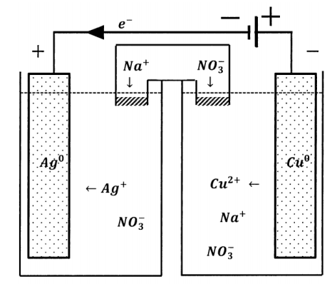
We can incorporate another potential source into the external circuit of an electrochemical cell. If we do so in such a way that the two electrical potentials augment one another, as diagrammed in Figure 4, the potential drop around the new external circuit is the sum of the potential drops of the two sources taken independently. The direction of electron flow is unchanged. An electron anywhere in the external circuit is propelled in the same direction by either potential source. The effective potential difference in the composite circuit is the sum of the potentials that the sources exhibit when each acts alone.

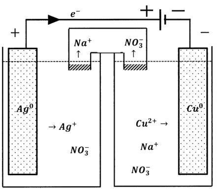
Alternatively, we can connect the two potential sources so that they oppose one another, as diagrammed in Figure 5. Now an electron in the external circuit is pushed in one direction by one of the potential sources and in the opposite direction by the other potential source. The effective potential difference in the composite circuit is the difference between the potentials that the sources exhibit when each acts alone. In the composite circuit, the direction of electron flow is determined by the potential source whose potential difference is greater.
This has a dramatic effect on the direction of the reaction occurring in the weaker cell. In the composite cell, the direction of electron flow through the weaker cell is opposite to the direction of electron flow when the weaker cell is operating as a galvanic cell. Since the direction of electron flow in the external circuit determines the directions in which the half-reactions occur, the chemical reaction that occurs in the cell must occur in the opposite direction also. When the direction of current flow through a cell is determined by connection to a greater potential difference in this fashion, the cell is called an electrolytic cell. Reduction occurs at the negative terminal of an electrolytic cell. In an electrolytic cell, the cathode is the electrically negative electrode. The direction of current flow in any cell can be reversed by the application of a sufficiently large counter-potential.
When a cell operates as a source of current (that is, as a galvanic cell), the cell reaction is a spontaneous process. Since, as the cell reaction proceeds, electrons move through a potential difference in the external circuit, the reaction releases energy in the cell’s surroundings. If the external circuit is simply a resistor, as when the terminals are short-circuited, the energy is released as heat. Let \(q\) be the heat released and let \(Q\) be the amount of charge passed through the external circuit in a time interval \(\Delta t\). The heat-release rate is given by
\[\frac{q}{\Delta t}=\frac{\Delta E}{\Delta t}=\frac{Q\mathcal{E}}{\Delta t} \nonumber \]
The electrical current is \(I={Q}/{\Delta t}\). If the resistor follows Ohm’s law, \(\mathcal{E}=IR\), where \(R\) is the magnitude of the resistance, the heat release rate becomes
\[\frac{q}{\Delta t}=I^2R \nonumber \]
As the reaction proceeds and energy is dissipated in the external circuit, the ability of the cell to supply further energy is continuously diminished. The energy delivered to the surroundings through the external circuit comes at the expense of the cell’s internal energy and corresponds to the depletion of the cell reactants.
When the chemical reaction occurring within a cell is driven by the application of an externally supplied potential difference, the opposite occurs. In the driven (electrolytic) cell, the direction of the cell reaction is opposite the direction of the spontaneous reaction that occurs when the cell operates galvanically. The electrolytic process produces the chemical reagents that are consumed in the spontaneous cell reaction. The external circuit delivers energy to the electrolytic cell, increasing its content of spontaneous-direction reactants and thereby increasing its ability to do work.
In summary, the essential difference between electrolytic and galvanic cells lies in the factor that determines the direction of current flow and, correspondingly, the direction in which the cell reaction occurs. In a galvanic cell, a spontaneous chemical reaction occurs and this reaction determines the direction of current flow and the signs of the electrode potentials. In an electrolytic cell, the sign of the electrode potentials is determined by an applied potential source, which determines the direction of current flow; the cell reaction proceeds in the non-spontaneous direction.


