7.22: A Quantum Circuit for a Michelson Interferometer
- Page ID
- 141691

Schematic diagram of a Mach‐Zehnder interferometer (MZI).
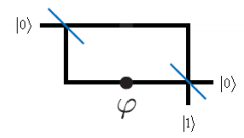
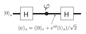
The following quantum circuit simulates the MZI.
The arms of the MZI are represented by the following orthonormal basis.
\[ | 0 \rangle = \begin{pmatrix} 1 \\ 0 \end{pmatrix} \nonumber \]
\[ |1 \rangle = \begin{pmatrix} 0 \\ 1 \end{pmatrix} \nonumber \]
The matrices representing the Hadamard and phase shift gates are:
\[ H = \frac{1}{ \sqrt{2}} \begin{pmatrix} 1 & 1 \\ 1 & -1 \end{pmatrix} \nonumber \]
\[ A ( \theta) = \begin{pmatrix} 1 & 0 \\ 0 & e^{i \phi} \end{pmatrix} \nonumber \]
Step‐by‐step through the circuit. The first Hadamard gate creates a superposition of the |0 > and |1 > states. The phase shifter operates on the lower arm of the MZI. The final Hadamard gate allows interference between the two arms of the MZI.
\[ H \begin{pmatrix} 1 \\ 0 \end{pmatrix} \rightarrow \begin{pmatrix} \frac{ \sqrt{2}}{2} \\ \frac{ \sqrt{2}}{2} \end{pmatrix} \nonumber \]
\[ A ( \phi) H \begin{pmatrix} 1 \\ 0 \end{pmatrix} \rightarrow \begin{pmatrix} \frac{ \sqrt{2}}{2} \\ \frac{ \sqrt{2} e^{ \phi i}}{2} \end{pmatrix} \nonumber \]
\[ H A ( \phi) H \begin{pmatrix} 1 \\ 0 \end{pmatrix} \rightarrow \begin{pmatrix} \frac{ e^{ \phi i}}{2} + \frac{1}{2} \\ \frac{1}{2} - \frac{ e^{ \phi i}}{2} \end{pmatrix} \nonumber \]
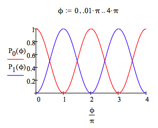
Probability of detection at the |0 > port:
\[ P_0 ( \phi) = \left[ \left| \begin{pmatrix} 1 & 0 \end{pmatrix} H A( \phi) H \begin{pmatrix} 1 \\ 0 \end{pmatrix} \right| \right]^2 |_{simplify}^{assume,~ \phi = real} \rightarrow \frac{ \cos \phi}{2} + \frac{1}{2} \nonumber \]
Probability of detection at the |1 > port:
\[ P_1 ( \phi) = \left[ \left| \begin{pmatrix} 0 & 1 \end{pmatrix} H A( \phi) H \begin{pmatrix} 1 \\ 0 \end{pmatrix} \right| \right]^2 |_{simplify}^{assume,~ \phi = real} \rightarrow \frac{1}{2} - \frac{ \cos \phi}{2} \nonumber \]
A graphical representation of the above calculations shows the interference effects as a function of ϕ.