
Microscopy - Overview
- Page ID
- 332
\( \newcommand{\vecs}[1]{\overset { \scriptstyle \rightharpoonup} {\mathbf{#1}} } \)
\( \newcommand{\vecd}[1]{\overset{-\!-\!\rightharpoonup}{\vphantom{a}\smash {#1}}} \)
\( \newcommand{\dsum}{\displaystyle\sum\limits} \)
\( \newcommand{\dint}{\displaystyle\int\limits} \)
\( \newcommand{\dlim}{\displaystyle\lim\limits} \)
\( \newcommand{\id}{\mathrm{id}}\) \( \newcommand{\Span}{\mathrm{span}}\)
( \newcommand{\kernel}{\mathrm{null}\,}\) \( \newcommand{\range}{\mathrm{range}\,}\)
\( \newcommand{\RealPart}{\mathrm{Re}}\) \( \newcommand{\ImaginaryPart}{\mathrm{Im}}\)
\( \newcommand{\Argument}{\mathrm{Arg}}\) \( \newcommand{\norm}[1]{\| #1 \|}\)
\( \newcommand{\inner}[2]{\langle #1, #2 \rangle}\)
\( \newcommand{\Span}{\mathrm{span}}\)
\( \newcommand{\id}{\mathrm{id}}\)
\( \newcommand{\Span}{\mathrm{span}}\)
\( \newcommand{\kernel}{\mathrm{null}\,}\)
\( \newcommand{\range}{\mathrm{range}\,}\)
\( \newcommand{\RealPart}{\mathrm{Re}}\)
\( \newcommand{\ImaginaryPart}{\mathrm{Im}}\)
\( \newcommand{\Argument}{\mathrm{Arg}}\)
\( \newcommand{\norm}[1]{\| #1 \|}\)
\( \newcommand{\inner}[2]{\langle #1, #2 \rangle}\)
\( \newcommand{\Span}{\mathrm{span}}\) \( \newcommand{\AA}{\unicode[.8,0]{x212B}}\)
\( \newcommand{\vectorA}[1]{\vec{#1}} % arrow\)
\( \newcommand{\vectorAt}[1]{\vec{\text{#1}}} % arrow\)
\( \newcommand{\vectorB}[1]{\overset { \scriptstyle \rightharpoonup} {\mathbf{#1}} } \)
\( \newcommand{\vectorC}[1]{\textbf{#1}} \)
\( \newcommand{\vectorD}[1]{\overrightarrow{#1}} \)
\( \newcommand{\vectorDt}[1]{\overrightarrow{\text{#1}}} \)
\( \newcommand{\vectE}[1]{\overset{-\!-\!\rightharpoonup}{\vphantom{a}\smash{\mathbf {#1}}}} \)
\( \newcommand{\vecs}[1]{\overset { \scriptstyle \rightharpoonup} {\mathbf{#1}} } \)
\(\newcommand{\longvect}{\overrightarrow}\)
\( \newcommand{\vecd}[1]{\overset{-\!-\!\rightharpoonup}{\vphantom{a}\smash {#1}}} \)
\(\newcommand{\avec}{\mathbf a}\) \(\newcommand{\bvec}{\mathbf b}\) \(\newcommand{\cvec}{\mathbf c}\) \(\newcommand{\dvec}{\mathbf d}\) \(\newcommand{\dtil}{\widetilde{\mathbf d}}\) \(\newcommand{\evec}{\mathbf e}\) \(\newcommand{\fvec}{\mathbf f}\) \(\newcommand{\nvec}{\mathbf n}\) \(\newcommand{\pvec}{\mathbf p}\) \(\newcommand{\qvec}{\mathbf q}\) \(\newcommand{\svec}{\mathbf s}\) \(\newcommand{\tvec}{\mathbf t}\) \(\newcommand{\uvec}{\mathbf u}\) \(\newcommand{\vvec}{\mathbf v}\) \(\newcommand{\wvec}{\mathbf w}\) \(\newcommand{\xvec}{\mathbf x}\) \(\newcommand{\yvec}{\mathbf y}\) \(\newcommand{\zvec}{\mathbf z}\) \(\newcommand{\rvec}{\mathbf r}\) \(\newcommand{\mvec}{\mathbf m}\) \(\newcommand{\zerovec}{\mathbf 0}\) \(\newcommand{\onevec}{\mathbf 1}\) \(\newcommand{\real}{\mathbb R}\) \(\newcommand{\twovec}[2]{\left[\begin{array}{r}#1 \\ #2 \end{array}\right]}\) \(\newcommand{\ctwovec}[2]{\left[\begin{array}{c}#1 \\ #2 \end{array}\right]}\) \(\newcommand{\threevec}[3]{\left[\begin{array}{r}#1 \\ #2 \\ #3 \end{array}\right]}\) \(\newcommand{\cthreevec}[3]{\left[\begin{array}{c}#1 \\ #2 \\ #3 \end{array}\right]}\) \(\newcommand{\fourvec}[4]{\left[\begin{array}{r}#1 \\ #2 \\ #3 \\ #4 \end{array}\right]}\) \(\newcommand{\cfourvec}[4]{\left[\begin{array}{c}#1 \\ #2 \\ #3 \\ #4 \end{array}\right]}\) \(\newcommand{\fivevec}[5]{\left[\begin{array}{r}#1 \\ #2 \\ #3 \\ #4 \\ #5 \\ \end{array}\right]}\) \(\newcommand{\cfivevec}[5]{\left[\begin{array}{c}#1 \\ #2 \\ #3 \\ #4 \\ #5 \\ \end{array}\right]}\) \(\newcommand{\mattwo}[4]{\left[\begin{array}{rr}#1 \amp #2 \\ #3 \amp #4 \\ \end{array}\right]}\) \(\newcommand{\laspan}[1]{\text{Span}\{#1\}}\) \(\newcommand{\bcal}{\cal B}\) \(\newcommand{\ccal}{\cal C}\) \(\newcommand{\scal}{\cal S}\) \(\newcommand{\wcal}{\cal W}\) \(\newcommand{\ecal}{\cal E}\) \(\newcommand{\coords}[2]{\left\{#1\right\}_{#2}}\) \(\newcommand{\gray}[1]{\color{gray}{#1}}\) \(\newcommand{\lgray}[1]{\color{lightgray}{#1}}\) \(\newcommand{\rank}{\operatorname{rank}}\) \(\newcommand{\row}{\text{Row}}\) \(\newcommand{\col}{\text{Col}}\) \(\renewcommand{\row}{\text{Row}}\) \(\newcommand{\nul}{\text{Nul}}\) \(\newcommand{\var}{\text{Var}}\) \(\newcommand{\corr}{\text{corr}}\) \(\newcommand{\len}[1]{\left|#1\right|}\) \(\newcommand{\bbar}{\overline{\bvec}}\) \(\newcommand{\bhat}{\widehat{\bvec}}\) \(\newcommand{\bperp}{\bvec^\perp}\) \(\newcommand{\xhat}{\widehat{\xvec}}\) \(\newcommand{\vhat}{\widehat{\vvec}}\) \(\newcommand{\uhat}{\widehat{\uvec}}\) \(\newcommand{\what}{\widehat{\wvec}}\) \(\newcommand{\Sighat}{\widehat{\Sigma}}\) \(\newcommand{\lt}{<}\) \(\newcommand{\gt}{>}\) \(\newcommand{\amp}{&}\) \(\definecolor{fillinmathshade}{gray}{0.9}\)The word microscopy comes from the Greek words for small and to view. On April 13, 1625, Giovanni Faber coined the term microscope. A microscope is an instrument that enables us to view small objects that are otherwise invisible to our naked eye. One way that microscopes allow us to see smaller objects is through the process of magnification, i.e. enlarging the image of the object. When a microscope enlarges an image of a 1 mm object to 10 mm, this is a 10 x magnification.
Introduction
Lens: The lens is the part of a microscope that bends a beam of light and focuses this on the object or sample.
Spatial Resolution
The resolution of a microscope is the smallest distance between two objects that results in two images that are distinguishable from each other. For example, the resolution of our eyes ranges from 0.1 to 0.2 mm. This means that our eyes can distinguish between two objects that are separated by 0.1 to 0.2 mm.
Light Microscopy
Early Light Microscopes
- There is evidence of people using different kinds of materials (beads, crystals, water droplets) as lenses and using light as medium to see smaller objects. However, it is not very clear who invented the first microscope and when this happened.
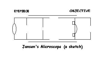
- In 1595, Hans Jansen or his son Zacharias of Holland invented the first compound microscope. A compound microscope is a microscope with two or more lenses.
- A person by the name of Robert Hooke (1635-1703) also liked to make and use compound microscopes. His microscopes enabled him to see small objects such as eyes of insects and point of needles.
- Around 1668, Antony van Leeuwenhoek (1632-1723), a Dutch draper, started making simple microscopes (microscopes with single lenses). He made over 500 single lens microscopes and some of these could magnify up to 300 times.
Polarizing Microscope
Light has both a particle and a wave property. A beam of light can be polarized by lining up its vibrations with each other. Thus, the polarizing microscope polarizes light in order to magnify images. This microscope also determines properties of materials that transmit light, whether they are crystalline or non crystalline.
The optical features of transparent material were recognized when William Henry Fox Talbot added two Nicol prisms (prisms that can polarize light) to a microscope. However, it was Henry Clifton Sorby (1826-1908) who used polarized light microscopy to study thinned sections of transparent rocks. He showed that through their optical properties, these thinned sections of minerals could be analyzed.
The polarizing microscope can be divided into three major component sets:
- Stand holds the body tube and the stage
- Optical system consists of the source of light, usually a lamp
- System for production of plane polarized light these devices consist of a polarizer and an analyser and these determine the resolving power or resolution
The quality of magnification depends on the objective lens and the smaller the diameter of the outermost lens, the higher the magnification.
Reflected Light Microscopy
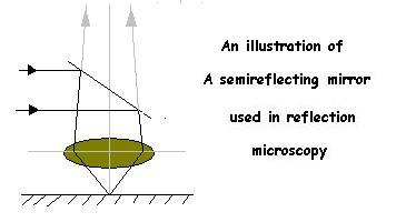
In 1740, Dr. Johann N. Lieberkuhn authenticated an instrument for illuminating opaque materials that had a cup shaped mirror encircling the objective lens of a microscope. This mirror is called a reflector. A reflector has a concave reflecting surface and a lens in its center. This evenly illuminates the specimen when the specimen is fixed up to the light and the light rays reflected from it and to the specimen.
Henry Clifton Sorby used a small reflector and attached this over the objective lens of his microscope. When he used this to study steel, he was able to see residues and distinguish these from the hard components of the steel. From then on, several scientists that study minerals also used reflected light microscopes and this technology improved throughout time.
Near-Field Scanning Light Microscope
Professor Michael Isaacson of Cornell University invented this type of a microscope. This microscope also uses light but not lenses. In order to focus the light on a sample, Isaacson passed light through a very tiny hole. The hole and the sample are so closed together that the light beam does not spread out. This type of a microscope enabled Isaacson's team to resolve up to 40 nm when they used yellow-green light. In this type of a microscope, the resolution is not really limited by the wavelength of light but the amount of the sample since it is very small.
Electron Microscopy
Because they only have resolutions in the micrometer range by using visible light, the light microscopes cannot be used to see in the nanometer range. In order to see in the nanometer range, we would need something that has higher energy than visible light. A physicist named de Broglie came up with an equation that shows the shorter the wavelength of a wave, the higher the energy it has. From the wave-particle duality, we know that matter, like light, can have both wave and particle properties. This means that we can also use matter, like electrons, instead of light. Electrons have shorter wavelengths than light and thus have higher energy and better resolution.
Electron microscopes use electrons to focus on a sample. In 1926-1927, Busch demonstrated that an appropriately shaped magnetic field could be used as a lens. This discovery made it possible to use magnetic fields to focus the electron beam for electron microscopes.
Transmission Electron Microscope (TEM)
After Busch’s discovery and development of electron microscopes, companies in different parts of the world developed and produced a prototype of an electron microscope called Transmission Electron Microscopes (TEM). In TEM, the beam of electrons goes through the sample and their interactions are seen on the side of the sample where the beam exits. Then, the image is gathered on a screen. TEMs consist of three major parts:
- Electron source (electron gun)
- System of image production
- System of image recording
TEM has a typical resolution of approximately 2 nm. However, the sample has to be thin enough to transmit electrons so it cannot be used to look at living cells.
Scanning Electron Microscope (SEM)
In 1942, Zworykin, Hillier, and R.L. Snyder developed another type of an electron microscope called Scanning Electron Microscope (SEM). SEM is another example of an electron microscope and is arguably the most widely used electron beam instrument. In SEM, the electron beam excites the sample and its radiation is detected and photographed. SEM is a mapping device—a beam of electrons scanning across the surface of the sample creates the overall image. SEM also consists of major parts:
- Electron source (electron gun)
- System of lenses
- Collector of electrons
- System of image production
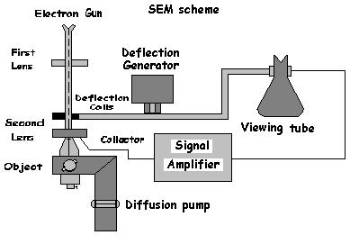
SEM’s resolution is about 20 nm and its magnification is about 200,000x. SEM cannot be used to study living cells as well since the sample for this process must be very dry.
Scanning Probe Microscopy (SPM)
Scanning probe microscopes are also capable of magnifying or creating images of samples in the nanometer range. Some of them can even give details up to the atomic level.
Examples of Scanning Probe Microscopes
Scanning Tunneling Microscopy (STM)
Briab Josephson shared when he explained Tunneling. This phenomenon eventually led to the development of Scanning Tunneling Microscopes by Heinrich Rohrer and Gerd Binnig around 1979. Rohrer and Binnig received the Nobel Prize in physics in 1986. The STM uses an electron conductor needle, composed of either platinum-rhodium or tungsten, as a probe to scan across the surface of a solid that conducts electricity as well. The tip of the needle is usually very fine; it may even be a single atom that is 0.2 nm wide. Electrons tunnel across the space between the tip of the needle and the specimen surface when the tip and the surface are very close to each other. The tunneling current is very sensitive to the distance of the tip from the surface. As a result, the needle moves up and down depending on the surface of the solid—a piezoelectric cylinder monitors this movement. The three-dimensional image of the surface is then projected on a computer screen.
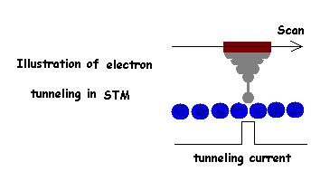
The STM has a resolution of about 0.1 nm. However, the fact that the needle-tip and the sample must be electrical conductors limits the amount of materials that can be studied using this technology.
Atomic Force Microscope (AFM)
In 1986, Binnig, Berger, and Calvin Quate invented the first derivative of the STM—the Atomic Force Microscope. The AFM is another type of a scanning microscope that scans the surface of the sample. It is different from the STM because it does not measure the current between the tip of the needle and the sample. The AFM has a stylus with a sharp tip that is attached on the end of a long a cantilever. As the stylus scans the sample, the force of the surface pushes or pulls it. The cantilever deflects as a result and a laser beam is used to measure this deflection. This deflection is then turned into a three dimensional topographic image by a computer.
With AFM, a much higher resolution is attained with less sample damage. The AFM can be used on non-conducting samples as well as on liquid samples because there is no current applied on the sample. Thus the AFM can be used to study biological molecules such as cells and proteins.
References
- Atkins, Peter and de Paula, Julio. Physical Chemistry for the Life Sciences. New York, N.Y.: W. H. Freeman Company, 2006. (344-345, 356-357).
- Croft, William J. Under the Microscope: a brief history of microscopy. Singapore: Mainland Press, 2006.
- Rochow, Theodore George and Tucker, Paul Arthur. Introduction to Microscopy by means of light, electrons, x rays, or acoustics. New York, N.Y.: Plenum Press, 1994. (1-18)