23.1: Reference Electrodes
- Page ID
- 333586

\( \newcommand{\vecs}[1]{\overset { \scriptstyle \rightharpoonup} {\mathbf{#1}} } \)
\( \newcommand{\vecd}[1]{\overset{-\!-\!\rightharpoonup}{\vphantom{a}\smash {#1}}} \)
\( \newcommand{\dsum}{\displaystyle\sum\limits} \)
\( \newcommand{\dint}{\displaystyle\int\limits} \)
\( \newcommand{\dlim}{\displaystyle\lim\limits} \)
\( \newcommand{\id}{\mathrm{id}}\) \( \newcommand{\Span}{\mathrm{span}}\)
( \newcommand{\kernel}{\mathrm{null}\,}\) \( \newcommand{\range}{\mathrm{range}\,}\)
\( \newcommand{\RealPart}{\mathrm{Re}}\) \( \newcommand{\ImaginaryPart}{\mathrm{Im}}\)
\( \newcommand{\Argument}{\mathrm{Arg}}\) \( \newcommand{\norm}[1]{\| #1 \|}\)
\( \newcommand{\inner}[2]{\langle #1, #2 \rangle}\)
\( \newcommand{\Span}{\mathrm{span}}\)
\( \newcommand{\id}{\mathrm{id}}\)
\( \newcommand{\Span}{\mathrm{span}}\)
\( \newcommand{\kernel}{\mathrm{null}\,}\)
\( \newcommand{\range}{\mathrm{range}\,}\)
\( \newcommand{\RealPart}{\mathrm{Re}}\)
\( \newcommand{\ImaginaryPart}{\mathrm{Im}}\)
\( \newcommand{\Argument}{\mathrm{Arg}}\)
\( \newcommand{\norm}[1]{\| #1 \|}\)
\( \newcommand{\inner}[2]{\langle #1, #2 \rangle}\)
\( \newcommand{\Span}{\mathrm{span}}\) \( \newcommand{\AA}{\unicode[.8,0]{x212B}}\)
\( \newcommand{\vectorA}[1]{\vec{#1}} % arrow\)
\( \newcommand{\vectorAt}[1]{\vec{\text{#1}}} % arrow\)
\( \newcommand{\vectorB}[1]{\overset { \scriptstyle \rightharpoonup} {\mathbf{#1}} } \)
\( \newcommand{\vectorC}[1]{\textbf{#1}} \)
\( \newcommand{\vectorD}[1]{\overrightarrow{#1}} \)
\( \newcommand{\vectorDt}[1]{\overrightarrow{\text{#1}}} \)
\( \newcommand{\vectE}[1]{\overset{-\!-\!\rightharpoonup}{\vphantom{a}\smash{\mathbf {#1}}}} \)
\( \newcommand{\vecs}[1]{\overset { \scriptstyle \rightharpoonup} {\mathbf{#1}} } \)
\(\newcommand{\longvect}{\overrightarrow}\)
\( \newcommand{\vecd}[1]{\overset{-\!-\!\rightharpoonup}{\vphantom{a}\smash {#1}}} \)
\(\newcommand{\avec}{\mathbf a}\) \(\newcommand{\bvec}{\mathbf b}\) \(\newcommand{\cvec}{\mathbf c}\) \(\newcommand{\dvec}{\mathbf d}\) \(\newcommand{\dtil}{\widetilde{\mathbf d}}\) \(\newcommand{\evec}{\mathbf e}\) \(\newcommand{\fvec}{\mathbf f}\) \(\newcommand{\nvec}{\mathbf n}\) \(\newcommand{\pvec}{\mathbf p}\) \(\newcommand{\qvec}{\mathbf q}\) \(\newcommand{\svec}{\mathbf s}\) \(\newcommand{\tvec}{\mathbf t}\) \(\newcommand{\uvec}{\mathbf u}\) \(\newcommand{\vvec}{\mathbf v}\) \(\newcommand{\wvec}{\mathbf w}\) \(\newcommand{\xvec}{\mathbf x}\) \(\newcommand{\yvec}{\mathbf y}\) \(\newcommand{\zvec}{\mathbf z}\) \(\newcommand{\rvec}{\mathbf r}\) \(\newcommand{\mvec}{\mathbf m}\) \(\newcommand{\zerovec}{\mathbf 0}\) \(\newcommand{\onevec}{\mathbf 1}\) \(\newcommand{\real}{\mathbb R}\) \(\newcommand{\twovec}[2]{\left[\begin{array}{r}#1 \\ #2 \end{array}\right]}\) \(\newcommand{\ctwovec}[2]{\left[\begin{array}{c}#1 \\ #2 \end{array}\right]}\) \(\newcommand{\threevec}[3]{\left[\begin{array}{r}#1 \\ #2 \\ #3 \end{array}\right]}\) \(\newcommand{\cthreevec}[3]{\left[\begin{array}{c}#1 \\ #2 \\ #3 \end{array}\right]}\) \(\newcommand{\fourvec}[4]{\left[\begin{array}{r}#1 \\ #2 \\ #3 \\ #4 \end{array}\right]}\) \(\newcommand{\cfourvec}[4]{\left[\begin{array}{c}#1 \\ #2 \\ #3 \\ #4 \end{array}\right]}\) \(\newcommand{\fivevec}[5]{\left[\begin{array}{r}#1 \\ #2 \\ #3 \\ #4 \\ #5 \\ \end{array}\right]}\) \(\newcommand{\cfivevec}[5]{\left[\begin{array}{c}#1 \\ #2 \\ #3 \\ #4 \\ #5 \\ \end{array}\right]}\) \(\newcommand{\mattwo}[4]{\left[\begin{array}{rr}#1 \amp #2 \\ #3 \amp #4 \\ \end{array}\right]}\) \(\newcommand{\laspan}[1]{\text{Span}\{#1\}}\) \(\newcommand{\bcal}{\cal B}\) \(\newcommand{\ccal}{\cal C}\) \(\newcommand{\scal}{\cal S}\) \(\newcommand{\wcal}{\cal W}\) \(\newcommand{\ecal}{\cal E}\) \(\newcommand{\coords}[2]{\left\{#1\right\}_{#2}}\) \(\newcommand{\gray}[1]{\color{gray}{#1}}\) \(\newcommand{\lgray}[1]{\color{lightgray}{#1}}\) \(\newcommand{\rank}{\operatorname{rank}}\) \(\newcommand{\row}{\text{Row}}\) \(\newcommand{\col}{\text{Col}}\) \(\renewcommand{\row}{\text{Row}}\) \(\newcommand{\nul}{\text{Nul}}\) \(\newcommand{\var}{\text{Var}}\) \(\newcommand{\corr}{\text{corr}}\) \(\newcommand{\len}[1]{\left|#1\right|}\) \(\newcommand{\bbar}{\overline{\bvec}}\) \(\newcommand{\bhat}{\widehat{\bvec}}\) \(\newcommand{\bperp}{\bvec^\perp}\) \(\newcommand{\xhat}{\widehat{\xvec}}\) \(\newcommand{\vhat}{\widehat{\vvec}}\) \(\newcommand{\uhat}{\widehat{\uvec}}\) \(\newcommand{\what}{\widehat{\wvec}}\) \(\newcommand{\Sighat}{\widehat{\Sigma}}\) \(\newcommand{\lt}{<}\) \(\newcommand{\gt}{>}\) \(\newcommand{\amp}{&}\) \(\definecolor{fillinmathshade}{gray}{0.9}\)In potentiometry we measure the difference between the potential of two electrodes. The potential of one electrode—the working or indicator electrode—responds to the analyte’s activity and the other electrode—the counter or reference electrode—has a known, fixed potential. By convention, the reference electrode is the anode; thus, the short hand notation for a potentiometric electrochemical cell is
reference electrode || indicator electrode
and the cell potential is
\[E_{\mathrm{cell}}=E_{\mathrm{ind}}-E_{\mathrm{ref}} \nonumber \]
The ideal reference electrode provides a stable, known potential so that we can attribute any change in Ecell to the analyte’s effect on the indicator electrode’s potential. In addition, the reference electrode should be easy to make and easy to use. Although the standard hydrogen electrode is the reference electrode used to define electrode potentials, it use is not common. Instead, the two reference electrodes discussed in this section find the most applications.
Calomel Electrodes
A calomel reference electrode is based on the following redox couple between Hg2Cl2 and Hg (calomel is the common name for Hg2Cl2)
\[\mathrm{Hg}_{2} \mathrm{Cl}_{2}(s)+2 e^{-}\rightleftharpoons2 \mathrm{Hg}(l)+2 \mathrm{Cl}^{-}(a q) \nonumber \]
for which the potential is
\[E=E_{\mathrm{Hg}_{2} \mathrm{Cl}_{2} / \mathrm{Hg}}^{\mathrm{o}}-\frac{0.05916}{2} \log \left(a_{\text{Cl}^-}\right)^{2}=+0.2682 \mathrm{V}-\frac{0.05916}{2} \log \left(a_{\text{Cl}^-}\right)^{2} \nonumber \]
The potential of a calomel electrode, therefore, depends on the activity of Cl– in equilibrium with Hg and Hg2Cl2.
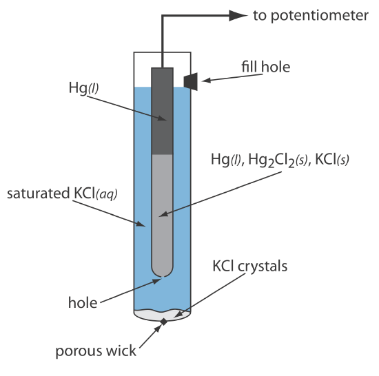
As shown in Figure \(\PageIndex{1}\), in a saturated calomel electrode (SCE) the concentration of Cl– is determined by the solubility of KCl. The electrode consists of an inner tube packed with a paste of Hg, Hg2Cl2, and KCl, situated within a second tube that contains a saturated solution of KCl. A small hole connects the two tubes and a porous wick serves as a salt bridge to the solution in which the SCE is immersed. A stopper in the outer tube provides an opening for adding addition saturated KCl. The short hand notation for this cell is
\[\mathrm{Hg}(l) | \mathrm{Hg}_{2} \mathrm{Cl}_{2}(s), \mathrm{KCl}(a q, \text { sat'd }) \| \nonumber \]
Because the concentration of Cl– is fixed by the solubility of KCl, the potential of an SCE remains constant even if we lose some of the inner solution to evaporation. A significant disadvantage of the SCE is that the solubility of KCl is sensitive to a change in temperature. At higher temperatures the solubility of KCl increases and the electrode’s potential decreases. For example, the potential of the SCE is +0.2444 V at 25oC and +0.2376 V at 35oC. The potential of a calomel electrode that contains an unsaturated solution of KCl is less dependent on the temperature, but its potential changes if the concentration, and thus the activity of Cl–, increases due to evaporation.
For example, the potential of a calomel electrode is +0.280 V when the concentration of KCl is 1.00 M and +0.336 V when the concentration of KCl is 0.100 M. If the activity of Cl– is 1.00, the potential is +0.2682 V.
Silver/Silver Chloride Electrodes
Another common reference electrode is the silver/silver chloride electrode, which is based on the reduction of AgCl to Ag.
\[\operatorname{AgCl}(s)+e^{-} \rightleftharpoons \mathrm{Ag}(s)+\mathrm{Cl}^{-}(a q) \nonumber \]
As is the case for the calomel electrode, the activity of Cl– determines the potential of the Ag/AgCl electrode; thus
\[E = E_\text{AgCl/Ag}^{\circ}-0.05916 \log a_{\text{Cl}^-} = 0.2223 \text{ V} - 0.05916 \log a_{\text{Cl}^-} \nonumber \]
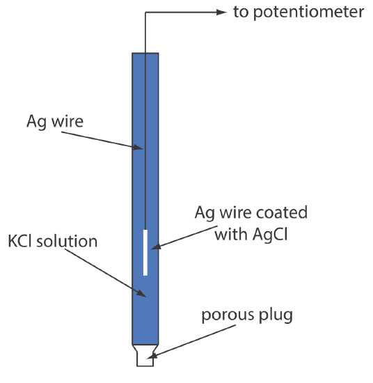
When prepared using a saturated solution of KCl, the electrode's potential is +0.197 V at 25oC. Another common Ag/AgCl electrode uses a solution of 3.5 M KCl and has a potential of +0.205 V at 25oC. As you might expect, the potential of a Ag/AgCl electrode using a saturated solution of KCl is more sensitive to a change in temperature than an electrode that uses an unsaturated solution of KCl.
A typical Ag/AgCl electrode is shown in Figure \(\PageIndex{2}\) and consists of a silver wire, the end of which is coated with a thin film of AgCl, immersed in a solution that contains the desired concentration of KCl. A porous plug serves as the salt bridge. The electrode’s short hand notation is
\[\operatorname{Ag}(s) | \operatorname{Ag} \mathrm{Cl}(s), \mathrm{KCl}\left(a q, a_{\mathrm{Cl}^{-}}=x\right) \| \nonumber \]
Converting Potentials Between Reference Electrodes
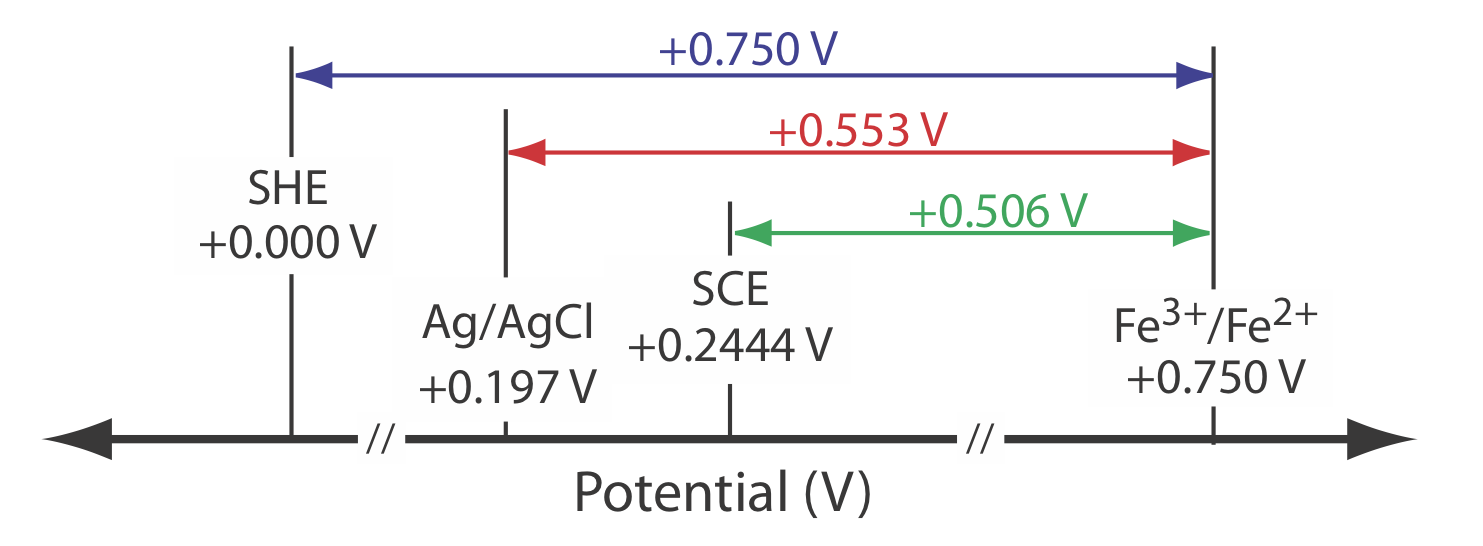
The standard state reduction potentials in most tables are reported relative to the standard hydrogen electrode’s potential of +0.00 V. Because we rarely use the SHE as a reference electrode, we need to convert an indicator electrode’s potential to its equivalent value when using a different reference electrode. As shown in the following example, this is easy to do.
The potential for an Fe3+/Fe2+ half-cell is +0.750 V relative to the standard hydrogen electrode. What is its potential if we use a saturated calomel electrode or a saturated silver/silver chloride electrode?
Solution
When we use a standard hydrogen electrode the potential of the electrochemical cell is
\[E_\text{cell} = E_{\text{Fe}^{3+}/\text{Fe}^{2+}} - E_\text{SHE} = 0.750 \text{ V} -0.000 \text{ V} = 0.750 \text{ V} \nonumber \]
We can use the same equation to calculate the potential if we use a saturated calomel electrode
\[E_\text{cell} = E_{\text{Fe}^{3+}/\text{Fe}^{2+}} - E_\text{SHE} = 0.750 \text{ V} -0.2444 \text{ V} = 0.506 \text{ V} \nonumber \]
or a saturated silver/silver chloride electrode
\[E_\text{cell} = E_{\text{Fe}^{3+}/\text{Fe}^{2+}} - E_\text{SHE} = 0.750 \text{ V} -0.197 \text{ V} = 0.553 \text{ V} \nonumber \]
Figure \(\PageIndex{3}\) provides a pictorial representation of the relationship between these different potentials.