
3.4: Mathematical Operations Using Operational Amplifiers
- Page ID
- 406445

\( \newcommand{\vecs}[1]{\overset { \scriptstyle \rightharpoonup} {\mathbf{#1}} } \)
\( \newcommand{\vecd}[1]{\overset{-\!-\!\rightharpoonup}{\vphantom{a}\smash {#1}}} \)
\( \newcommand{\id}{\mathrm{id}}\) \( \newcommand{\Span}{\mathrm{span}}\)
( \newcommand{\kernel}{\mathrm{null}\,}\) \( \newcommand{\range}{\mathrm{range}\,}\)
\( \newcommand{\RealPart}{\mathrm{Re}}\) \( \newcommand{\ImaginaryPart}{\mathrm{Im}}\)
\( \newcommand{\Argument}{\mathrm{Arg}}\) \( \newcommand{\norm}[1]{\| #1 \|}\)
\( \newcommand{\inner}[2]{\langle #1, #2 \rangle}\)
\( \newcommand{\Span}{\mathrm{span}}\)
\( \newcommand{\id}{\mathrm{id}}\)
\( \newcommand{\Span}{\mathrm{span}}\)
\( \newcommand{\kernel}{\mathrm{null}\,}\)
\( \newcommand{\range}{\mathrm{range}\,}\)
\( \newcommand{\RealPart}{\mathrm{Re}}\)
\( \newcommand{\ImaginaryPart}{\mathrm{Im}}\)
\( \newcommand{\Argument}{\mathrm{Arg}}\)
\( \newcommand{\norm}[1]{\| #1 \|}\)
\( \newcommand{\inner}[2]{\langle #1, #2 \rangle}\)
\( \newcommand{\Span}{\mathrm{span}}\) \( \newcommand{\AA}{\unicode[.8,0]{x212B}}\)
\( \newcommand{\vectorA}[1]{\vec{#1}} % arrow\)
\( \newcommand{\vectorAt}[1]{\vec{\text{#1}}} % arrow\)
\( \newcommand{\vectorB}[1]{\overset { \scriptstyle \rightharpoonup} {\mathbf{#1}} } \)
\( \newcommand{\vectorC}[1]{\textbf{#1}} \)
\( \newcommand{\vectorD}[1]{\overrightarrow{#1}} \)
\( \newcommand{\vectorDt}[1]{\overrightarrow{\text{#1}}} \)
\( \newcommand{\vectE}[1]{\overset{-\!-\!\rightharpoonup}{\vphantom{a}\smash{\mathbf {#1}}}} \)
\( \newcommand{\vecs}[1]{\overset { \scriptstyle \rightharpoonup} {\mathbf{#1}} } \)
\( \newcommand{\vecd}[1]{\overset{-\!-\!\rightharpoonup}{\vphantom{a}\smash {#1}}} \)
\(\newcommand{\avec}{\mathbf a}\) \(\newcommand{\bvec}{\mathbf b}\) \(\newcommand{\cvec}{\mathbf c}\) \(\newcommand{\dvec}{\mathbf d}\) \(\newcommand{\dtil}{\widetilde{\mathbf d}}\) \(\newcommand{\evec}{\mathbf e}\) \(\newcommand{\fvec}{\mathbf f}\) \(\newcommand{\nvec}{\mathbf n}\) \(\newcommand{\pvec}{\mathbf p}\) \(\newcommand{\qvec}{\mathbf q}\) \(\newcommand{\svec}{\mathbf s}\) \(\newcommand{\tvec}{\mathbf t}\) \(\newcommand{\uvec}{\mathbf u}\) \(\newcommand{\vvec}{\mathbf v}\) \(\newcommand{\wvec}{\mathbf w}\) \(\newcommand{\xvec}{\mathbf x}\) \(\newcommand{\yvec}{\mathbf y}\) \(\newcommand{\zvec}{\mathbf z}\) \(\newcommand{\rvec}{\mathbf r}\) \(\newcommand{\mvec}{\mathbf m}\) \(\newcommand{\zerovec}{\mathbf 0}\) \(\newcommand{\onevec}{\mathbf 1}\) \(\newcommand{\real}{\mathbb R}\) \(\newcommand{\twovec}[2]{\left[\begin{array}{r}#1 \\ #2 \end{array}\right]}\) \(\newcommand{\ctwovec}[2]{\left[\begin{array}{c}#1 \\ #2 \end{array}\right]}\) \(\newcommand{\threevec}[3]{\left[\begin{array}{r}#1 \\ #2 \\ #3 \end{array}\right]}\) \(\newcommand{\cthreevec}[3]{\left[\begin{array}{c}#1 \\ #2 \\ #3 \end{array}\right]}\) \(\newcommand{\fourvec}[4]{\left[\begin{array}{r}#1 \\ #2 \\ #3 \\ #4 \end{array}\right]}\) \(\newcommand{\cfourvec}[4]{\left[\begin{array}{c}#1 \\ #2 \\ #3 \\ #4 \end{array}\right]}\) \(\newcommand{\fivevec}[5]{\left[\begin{array}{r}#1 \\ #2 \\ #3 \\ #4 \\ #5 \\ \end{array}\right]}\) \(\newcommand{\cfivevec}[5]{\left[\begin{array}{c}#1 \\ #2 \\ #3 \\ #4 \\ #5 \\ \end{array}\right]}\) \(\newcommand{\mattwo}[4]{\left[\begin{array}{rr}#1 \amp #2 \\ #3 \amp #4 \\ \end{array}\right]}\) \(\newcommand{\laspan}[1]{\text{Span}\{#1\}}\) \(\newcommand{\bcal}{\cal B}\) \(\newcommand{\ccal}{\cal C}\) \(\newcommand{\scal}{\cal S}\) \(\newcommand{\wcal}{\cal W}\) \(\newcommand{\ecal}{\cal E}\) \(\newcommand{\coords}[2]{\left\{#1\right\}_{#2}}\) \(\newcommand{\gray}[1]{\color{gray}{#1}}\) \(\newcommand{\lgray}[1]{\color{lightgray}{#1}}\) \(\newcommand{\rank}{\operatorname{rank}}\) \(\newcommand{\row}{\text{Row}}\) \(\newcommand{\col}{\text{Col}}\) \(\renewcommand{\row}{\text{Row}}\) \(\newcommand{\nul}{\text{Nul}}\) \(\newcommand{\var}{\text{Var}}\) \(\newcommand{\corr}{\text{corr}}\) \(\newcommand{\len}[1]{\left|#1\right|}\) \(\newcommand{\bbar}{\overline{\bvec}}\) \(\newcommand{\bhat}{\widehat{\bvec}}\) \(\newcommand{\bperp}{\bvec^\perp}\) \(\newcommand{\xhat}{\widehat{\xvec}}\) \(\newcommand{\vhat}{\widehat{\vvec}}\) \(\newcommand{\uhat}{\widehat{\uvec}}\) \(\newcommand{\what}{\widehat{\wvec}}\) \(\newcommand{\Sighat}{\widehat{\Sigma}}\) \(\newcommand{\lt}{<}\) \(\newcommand{\gt}{>}\) \(\newcommand{\amp}{&}\) \(\definecolor{fillinmathshade}{gray}{0.9}\)The circuit for comparing two voltages is an example of using an operational amplifier to complete a mathematical operation. In this section we will examine several additional examples of mathematical operations completed using operational amplifiers.
Multiplication and Division by a Constant
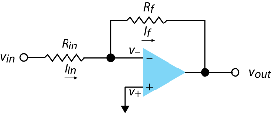
The inverting amplifier that we considered earlier, and that is reproduced here in Figure \(\PageIndex{1}\), returns an output voltage, \(v_{out}\) that multiplies the input voltage by an amount that depends on the ratio of the resistors \(R_{in}\) and \(R_f\).
\[v_{out} = - v_{in} \times \frac{R_f}{R_{in}} \label{math1} \]
Multiplication takes place when \(R_f > R_{in}\) and division takes place when \(R_{in} > R_f\). Note that there is a reversal in the sign of the voltage.
Addition or Subtraction
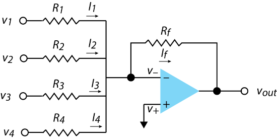
Figure \(\PageIndex{2}\) shows an operational amplifier circuit that adds together four separate input voltages. From our earlier analysis of circuits, you should see that
\[I_f = I_1 + I_2 + I_3 + I_4 \label{math2} \]
We can replace \(I_f\) in this equation using Ohm's law; thus
\[v_{out} = - R_f \times \left( \frac{v_1}{R_1} + \frac{v_2}{R_2} + \frac{v_3}{R_3} + \frac{v_4}{R_4} \right) \label{math3} \]
If all five of the resistors are identical, then \(v_{out}\) is a simple summation of the four input voltages.
\[v_{out} = - (v_1 + v_2 + v_3 + v_4) \label{math4} \]
If we choose \(R_f\) such that it is \(0.25 \times R_1\) and set \(R_1 = R_2 = R_3 = R_4\), then the output voltage is the average of the input voltages
\[v_{out} = - \frac{v_1 + v_2 + v_3 + v_4}{4} \label{math5} \]
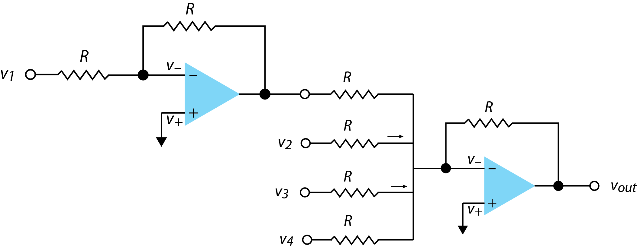
The voltage comparator covered in the last section subtracts one voltage from another. When more than two voltages are involved, then we can adapt the voltage adder circuit in Figure \(\PageIndex{2}\) to include subtraction by first running the voltage we wish to subtract through the inverting amplifier introduced in Chapter 3.2. Figure \(\PageIndex{3}\) shows this where \(v_{out} = - (v_4 + v_3 + v_2 - v_1)\).
Integration
Figure \(\PageIndex{4}\) shows an operational amplifier circuit that we can use to integrate a time-dependent signal. The circuit has a feedback loop, but it is built around a capacitor instead of a resistor because it stores charge over time. The circuit also has two switches that allow us to use the circuit over a specific period of time. When the hold switch is open, the input voltage cannot enter the circuit. Closing the hold switch sets \(t = t_0\). As long as the reset switch is open, current moves through the feedback loop. Opening the hold switch sets \(t = t_f\), where \(t_f\) is the total elapsed time. When this cycle is over, closing the reset switch drains the capacitor so that it is ready for its next use.
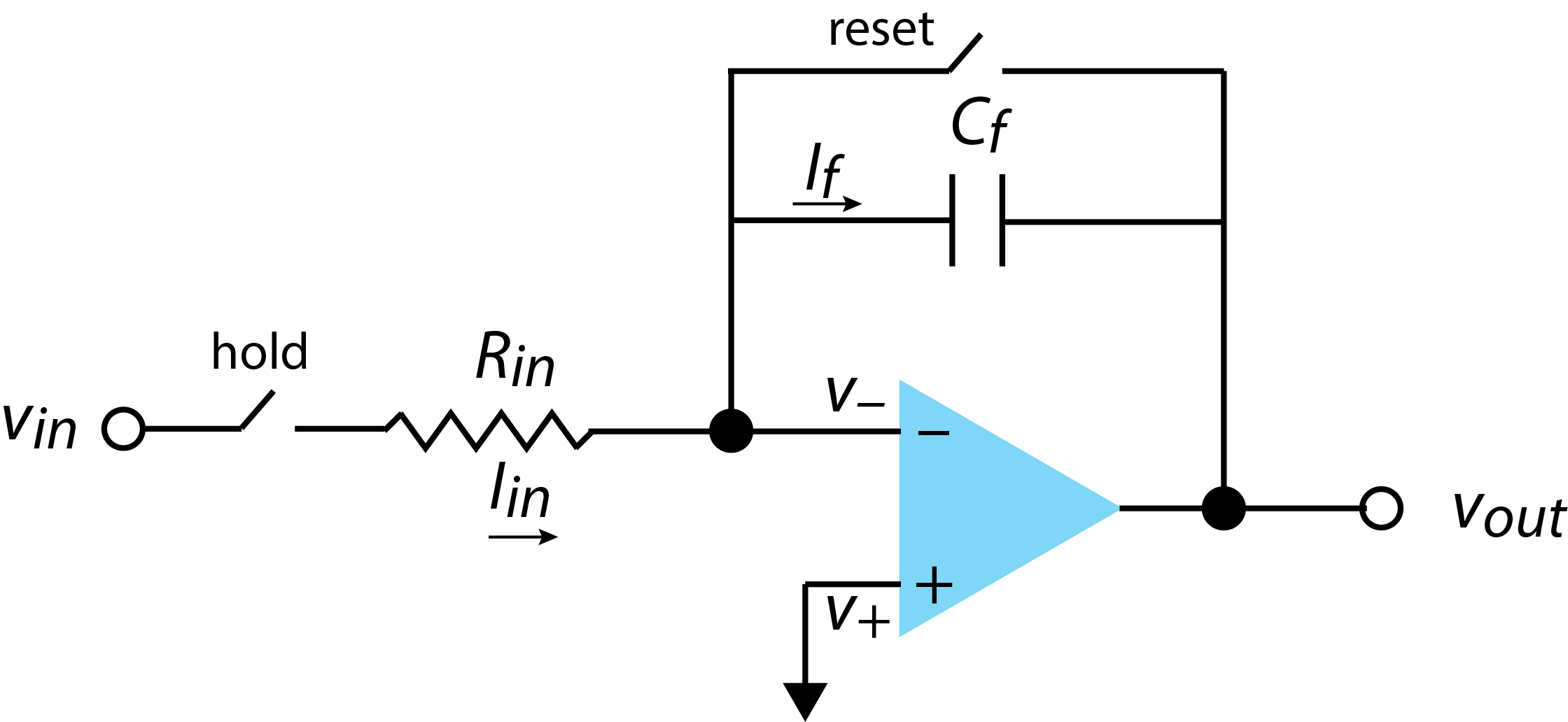
As we have seen several times, the current into the summing point, \(I_{in}\) is equal to the current in the feedback loop.
\[I_{in} = I_f \label{int1} \]
From Chapter 2, we know that the current in the feedback loop is \(I_f = - C_f \frac{d v_{out}}{dt}\) and, we know from Ohm's law that \(i_{in} = \frac{V_{in}}{R_{in}}\). Substituting both relationships into Equation \ref{int1} gives
\[\frac{V_{in}}{R_{in}} = - C_f \frac{d v_{out}}{dt} \label{int2} \]
Rearranging this equation
\[d v_{out} = -\frac{v_{in}}{R_i C_f} dt \label{int3} \]
and integrating over time gives
\[\int_{v_{out,1}}^{v_{out,2}} d v_{out} = -\frac{1}{R_{in} C_f} \int_{t_1}^{t_2} v_{in} dt \label{int4} \]
If we begin the integration having previously discharged the capacitor and define \(t_1\) as the the moment we close the hold switch and define \(t_2\) as the moment we reopen the hold switch, then Equation \ref{int4} becomes
\[v_{out} = -\frac{1}{R_{in} C_f} \int_{0}^{t} v_{in} dt \label{int5} \]
and the output voltage is the integral of the input voltage multiplied by \((-R_{in} C_f)^{-1}\).
Differentiation
Reversing the capacitor and the resistor in the circuit in Figure \(\PageIndex{4}\) coverts the circuit from one that returns the integral of the input signal, into one that returns the derivative of the input signal; Figure \(\PageIndex{5}\) shows the resulting circuit.
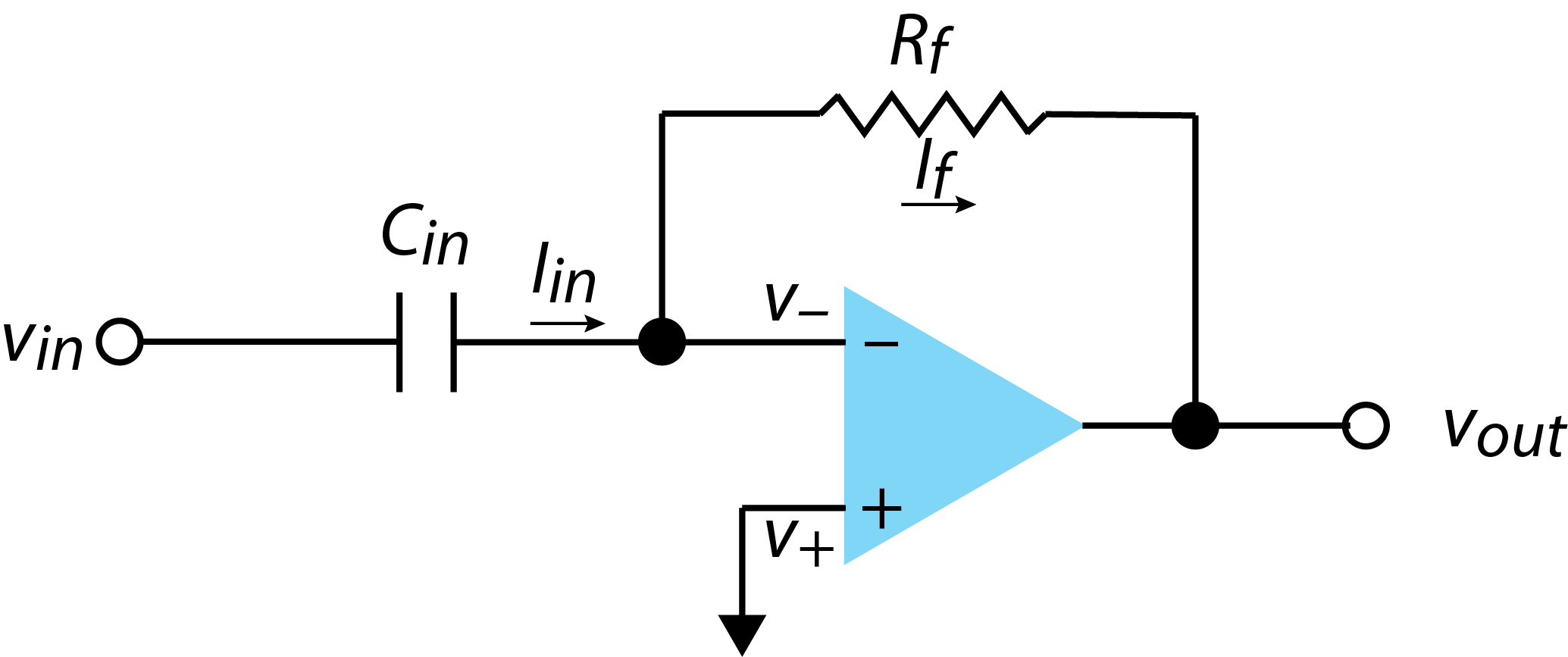
For this circuit we have \(I_{in} = C \times \frac{d v_{in}}{dt}\) and \(I_f = - \frac{V_{out}}{R}\). Given that \(I_{in} = I_f\), we are left with
\[- \frac{V_{out}}{R} = C \times \frac{d v_{in}}{dt} \label{deriv1} \]
\[v_{out} = - R C \times \frac{d v_{in}}{dt} \label{deriv2} \]