
3.1: Operational Amplifiers
- Page ID
- 406437

\( \newcommand{\vecs}[1]{\overset { \scriptstyle \rightharpoonup} {\mathbf{#1}} } \)
\( \newcommand{\vecd}[1]{\overset{-\!-\!\rightharpoonup}{\vphantom{a}\smash {#1}}} \)
\( \newcommand{\id}{\mathrm{id}}\) \( \newcommand{\Span}{\mathrm{span}}\)
( \newcommand{\kernel}{\mathrm{null}\,}\) \( \newcommand{\range}{\mathrm{range}\,}\)
\( \newcommand{\RealPart}{\mathrm{Re}}\) \( \newcommand{\ImaginaryPart}{\mathrm{Im}}\)
\( \newcommand{\Argument}{\mathrm{Arg}}\) \( \newcommand{\norm}[1]{\| #1 \|}\)
\( \newcommand{\inner}[2]{\langle #1, #2 \rangle}\)
\( \newcommand{\Span}{\mathrm{span}}\)
\( \newcommand{\id}{\mathrm{id}}\)
\( \newcommand{\Span}{\mathrm{span}}\)
\( \newcommand{\kernel}{\mathrm{null}\,}\)
\( \newcommand{\range}{\mathrm{range}\,}\)
\( \newcommand{\RealPart}{\mathrm{Re}}\)
\( \newcommand{\ImaginaryPart}{\mathrm{Im}}\)
\( \newcommand{\Argument}{\mathrm{Arg}}\)
\( \newcommand{\norm}[1]{\| #1 \|}\)
\( \newcommand{\inner}[2]{\langle #1, #2 \rangle}\)
\( \newcommand{\Span}{\mathrm{span}}\) \( \newcommand{\AA}{\unicode[.8,0]{x212B}}\)
\( \newcommand{\vectorA}[1]{\vec{#1}} % arrow\)
\( \newcommand{\vectorAt}[1]{\vec{\text{#1}}} % arrow\)
\( \newcommand{\vectorB}[1]{\overset { \scriptstyle \rightharpoonup} {\mathbf{#1}} } \)
\( \newcommand{\vectorC}[1]{\textbf{#1}} \)
\( \newcommand{\vectorD}[1]{\overrightarrow{#1}} \)
\( \newcommand{\vectorDt}[1]{\overrightarrow{\text{#1}}} \)
\( \newcommand{\vectE}[1]{\overset{-\!-\!\rightharpoonup}{\vphantom{a}\smash{\mathbf {#1}}}} \)
\( \newcommand{\vecs}[1]{\overset { \scriptstyle \rightharpoonup} {\mathbf{#1}} } \)
\( \newcommand{\vecd}[1]{\overset{-\!-\!\rightharpoonup}{\vphantom{a}\smash {#1}}} \)
\(\newcommand{\avec}{\mathbf a}\) \(\newcommand{\bvec}{\mathbf b}\) \(\newcommand{\cvec}{\mathbf c}\) \(\newcommand{\dvec}{\mathbf d}\) \(\newcommand{\dtil}{\widetilde{\mathbf d}}\) \(\newcommand{\evec}{\mathbf e}\) \(\newcommand{\fvec}{\mathbf f}\) \(\newcommand{\nvec}{\mathbf n}\) \(\newcommand{\pvec}{\mathbf p}\) \(\newcommand{\qvec}{\mathbf q}\) \(\newcommand{\svec}{\mathbf s}\) \(\newcommand{\tvec}{\mathbf t}\) \(\newcommand{\uvec}{\mathbf u}\) \(\newcommand{\vvec}{\mathbf v}\) \(\newcommand{\wvec}{\mathbf w}\) \(\newcommand{\xvec}{\mathbf x}\) \(\newcommand{\yvec}{\mathbf y}\) \(\newcommand{\zvec}{\mathbf z}\) \(\newcommand{\rvec}{\mathbf r}\) \(\newcommand{\mvec}{\mathbf m}\) \(\newcommand{\zerovec}{\mathbf 0}\) \(\newcommand{\onevec}{\mathbf 1}\) \(\newcommand{\real}{\mathbb R}\) \(\newcommand{\twovec}[2]{\left[\begin{array}{r}#1 \\ #2 \end{array}\right]}\) \(\newcommand{\ctwovec}[2]{\left[\begin{array}{c}#1 \\ #2 \end{array}\right]}\) \(\newcommand{\threevec}[3]{\left[\begin{array}{r}#1 \\ #2 \\ #3 \end{array}\right]}\) \(\newcommand{\cthreevec}[3]{\left[\begin{array}{c}#1 \\ #2 \\ #3 \end{array}\right]}\) \(\newcommand{\fourvec}[4]{\left[\begin{array}{r}#1 \\ #2 \\ #3 \\ #4 \end{array}\right]}\) \(\newcommand{\cfourvec}[4]{\left[\begin{array}{c}#1 \\ #2 \\ #3 \\ #4 \end{array}\right]}\) \(\newcommand{\fivevec}[5]{\left[\begin{array}{r}#1 \\ #2 \\ #3 \\ #4 \\ #5 \\ \end{array}\right]}\) \(\newcommand{\cfivevec}[5]{\left[\begin{array}{c}#1 \\ #2 \\ #3 \\ #4 \\ #5 \\ \end{array}\right]}\) \(\newcommand{\mattwo}[4]{\left[\begin{array}{rr}#1 \amp #2 \\ #3 \amp #4 \\ \end{array}\right]}\) \(\newcommand{\laspan}[1]{\text{Span}\{#1\}}\) \(\newcommand{\bcal}{\cal B}\) \(\newcommand{\ccal}{\cal C}\) \(\newcommand{\scal}{\cal S}\) \(\newcommand{\wcal}{\cal W}\) \(\newcommand{\ecal}{\cal E}\) \(\newcommand{\coords}[2]{\left\{#1\right\}_{#2}}\) \(\newcommand{\gray}[1]{\color{gray}{#1}}\) \(\newcommand{\lgray}[1]{\color{lightgray}{#1}}\) \(\newcommand{\rank}{\operatorname{rank}}\) \(\newcommand{\row}{\text{Row}}\) \(\newcommand{\col}{\text{Col}}\) \(\renewcommand{\row}{\text{Row}}\) \(\newcommand{\nul}{\text{Nul}}\) \(\newcommand{\var}{\text{Var}}\) \(\newcommand{\corr}{\text{corr}}\) \(\newcommand{\len}[1]{\left|#1\right|}\) \(\newcommand{\bbar}{\overline{\bvec}}\) \(\newcommand{\bhat}{\widehat{\bvec}}\) \(\newcommand{\bperp}{\bvec^\perp}\) \(\newcommand{\xhat}{\widehat{\xvec}}\) \(\newcommand{\vhat}{\widehat{\vvec}}\) \(\newcommand{\uhat}{\widehat{\uvec}}\) \(\newcommand{\what}{\widehat{\wvec}}\) \(\newcommand{\Sighat}{\widehat{\Sigma}}\) \(\newcommand{\lt}{<}\) \(\newcommand{\gt}{>}\) \(\newcommand{\amp}{&}\) \(\definecolor{fillinmathshade}{gray}{0.9}\)An operational amplifier (or op amp, for short) is an electrical circuit that has a variety of uses, a few of which we consider in this section: how to amplify and measure the signal from a transducer (detector), and how to perform mathematical operations on signals. In this section we will provide a basic overview of operational amplifiers without worrying about the specific internal details of its electrical circuit.
An excellent resource for this section and other sections in this chapter is Principles of Electronic Instrumentation by A. James Diefenderfer and published by W. B. Saunders Company, 1972.
Symbolic Representation of an Operational Amplifier
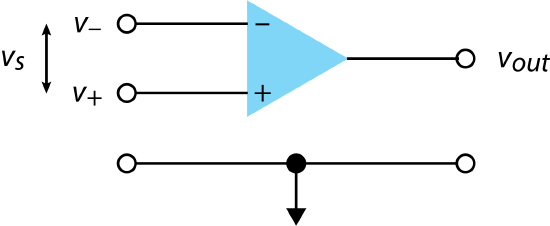
Figure \(\PageIndex{1}\) provides a symbolic representation of an operational amplifier. The large triangular shape is the operational amplifier, which is an extensive circuit whose exact design is not of interest to us; thus, the simple shape. The operational amplifier has two voltage inputs that are identified as \(v_{-}\) and as \(v_{+}\) and labeled as \(-\) and \(+\) on the op amp. The difference between \(v_{-}\) and \(v_{+}\) is defined as \(v_{s}\). The operational amplifier also has a single voltage output that is identified as \(v_{out}\). All voltages are measured relative to a circuit common of 0 V, represented by the small triangle at the bottom of the figure, that provides a shared reference; the circuit common is understood to be present even when it is not shown. Not included in this figure are the connections to a power supply, which are necessary for its operation.
Inverting and Noninverting Inputs
The minus sign and the plus sign that appear as labels on the op amp in Figure \(\PageIndex{1}\) do not mean that one input has a positive value and that the other input has a negative value. Instead, an input to the lead with a negative sign is inverted: if \(v_{-}\) is a negative DC voltage, then the output voltage, \(v_{out}\), is a positive DC voltage, and if \(v_{-}\) is a positive DC voltage, then the output voltage, \(v_{out}\), is a negative DC voltage. For an AC input to \(v_{-}\), the output is 180° out-of-phase, which implies a reversal in sign. The other input to the op amp is noninverting, which means that applying a positive voltage to \(v_{+}\) results in a positive signal at \(v_{out}\).
Key Properties of Operational Amplifiers
The ideal operational amplifier has several important properties that derive from its internal circuitry. The first of these properties is that the op amp's gain, \(A\), which is defined as the ratio of the output voltage to the input voltage
\[A_{op} = - \frac{v_{out}}{v_{s}} = - \frac{v_{out}}{v_{-} - v_{+}} \label{prop1} \]
is very large, typically on the order of 104 – 106. We need to be careful when we use the term gain as there can be a significant difference between the gain of the operational amplifier and the gain of the circuit that contains the operational amplifier. The gain of the operational amplifier, which is what we mean by Equation \ref{prop1}, is called the open-loop gain. The gain of a circuit that contains an operational amplifier is called a closed-loop gain. Where there is ambiguity, we will be careful to refer to the op amp's gain, \(A_{op}\), or to the circuit's gain, \(A_c\), as these are more descriptive.
A second property of an operational amplifier is that regardless of the specific values of \(v_{-}\) and \(v_{+}\), the op amp's internal circuitry is designed such that the current between the two inputs is effectively zero; in essence, the impedence, \(Z\), between the two inputs is so large that from Ohm's law, \(V = I \times Z\), the current between these two inputs is \(I \approx 0\). A large input impedence means we can connect our op amp to a high voltage source and know that it will draw a small current instead of overloading the circuit that includes the op amp.
A third property of an operational amplifier is that its output impedence is very small, which means we can draw a current from the circuit that meets our needs—this current is drawn from the op amp's power supply—even if the current into the op amp is zero. For example, if the circuit's gain is small, we can use the operational amplifier to provide a large gain in current.