
2.2: Direct Current (DC) Circuits
- Page ID
- 402750

\( \newcommand{\vecs}[1]{\overset { \scriptstyle \rightharpoonup} {\mathbf{#1}} } \)
\( \newcommand{\vecd}[1]{\overset{-\!-\!\rightharpoonup}{\vphantom{a}\smash {#1}}} \)
\( \newcommand{\id}{\mathrm{id}}\) \( \newcommand{\Span}{\mathrm{span}}\)
( \newcommand{\kernel}{\mathrm{null}\,}\) \( \newcommand{\range}{\mathrm{range}\,}\)
\( \newcommand{\RealPart}{\mathrm{Re}}\) \( \newcommand{\ImaginaryPart}{\mathrm{Im}}\)
\( \newcommand{\Argument}{\mathrm{Arg}}\) \( \newcommand{\norm}[1]{\| #1 \|}\)
\( \newcommand{\inner}[2]{\langle #1, #2 \rangle}\)
\( \newcommand{\Span}{\mathrm{span}}\)
\( \newcommand{\id}{\mathrm{id}}\)
\( \newcommand{\Span}{\mathrm{span}}\)
\( \newcommand{\kernel}{\mathrm{null}\,}\)
\( \newcommand{\range}{\mathrm{range}\,}\)
\( \newcommand{\RealPart}{\mathrm{Re}}\)
\( \newcommand{\ImaginaryPart}{\mathrm{Im}}\)
\( \newcommand{\Argument}{\mathrm{Arg}}\)
\( \newcommand{\norm}[1]{\| #1 \|}\)
\( \newcommand{\inner}[2]{\langle #1, #2 \rangle}\)
\( \newcommand{\Span}{\mathrm{span}}\) \( \newcommand{\AA}{\unicode[.8,0]{x212B}}\)
\( \newcommand{\vectorA}[1]{\vec{#1}} % arrow\)
\( \newcommand{\vectorAt}[1]{\vec{\text{#1}}} % arrow\)
\( \newcommand{\vectorB}[1]{\overset { \scriptstyle \rightharpoonup} {\mathbf{#1}} } \)
\( \newcommand{\vectorC}[1]{\textbf{#1}} \)
\( \newcommand{\vectorD}[1]{\overrightarrow{#1}} \)
\( \newcommand{\vectorDt}[1]{\overrightarrow{\text{#1}}} \)
\( \newcommand{\vectE}[1]{\overset{-\!-\!\rightharpoonup}{\vphantom{a}\smash{\mathbf {#1}}}} \)
\( \newcommand{\vecs}[1]{\overset { \scriptstyle \rightharpoonup} {\mathbf{#1}} } \)
\( \newcommand{\vecd}[1]{\overset{-\!-\!\rightharpoonup}{\vphantom{a}\smash {#1}}} \)
\(\newcommand{\avec}{\mathbf a}\) \(\newcommand{\bvec}{\mathbf b}\) \(\newcommand{\cvec}{\mathbf c}\) \(\newcommand{\dvec}{\mathbf d}\) \(\newcommand{\dtil}{\widetilde{\mathbf d}}\) \(\newcommand{\evec}{\mathbf e}\) \(\newcommand{\fvec}{\mathbf f}\) \(\newcommand{\nvec}{\mathbf n}\) \(\newcommand{\pvec}{\mathbf p}\) \(\newcommand{\qvec}{\mathbf q}\) \(\newcommand{\svec}{\mathbf s}\) \(\newcommand{\tvec}{\mathbf t}\) \(\newcommand{\uvec}{\mathbf u}\) \(\newcommand{\vvec}{\mathbf v}\) \(\newcommand{\wvec}{\mathbf w}\) \(\newcommand{\xvec}{\mathbf x}\) \(\newcommand{\yvec}{\mathbf y}\) \(\newcommand{\zvec}{\mathbf z}\) \(\newcommand{\rvec}{\mathbf r}\) \(\newcommand{\mvec}{\mathbf m}\) \(\newcommand{\zerovec}{\mathbf 0}\) \(\newcommand{\onevec}{\mathbf 1}\) \(\newcommand{\real}{\mathbb R}\) \(\newcommand{\twovec}[2]{\left[\begin{array}{r}#1 \\ #2 \end{array}\right]}\) \(\newcommand{\ctwovec}[2]{\left[\begin{array}{c}#1 \\ #2 \end{array}\right]}\) \(\newcommand{\threevec}[3]{\left[\begin{array}{r}#1 \\ #2 \\ #3 \end{array}\right]}\) \(\newcommand{\cthreevec}[3]{\left[\begin{array}{c}#1 \\ #2 \\ #3 \end{array}\right]}\) \(\newcommand{\fourvec}[4]{\left[\begin{array}{r}#1 \\ #2 \\ #3 \\ #4 \end{array}\right]}\) \(\newcommand{\cfourvec}[4]{\left[\begin{array}{c}#1 \\ #2 \\ #3 \\ #4 \end{array}\right]}\) \(\newcommand{\fivevec}[5]{\left[\begin{array}{r}#1 \\ #2 \\ #3 \\ #4 \\ #5 \\ \end{array}\right]}\) \(\newcommand{\cfivevec}[5]{\left[\begin{array}{c}#1 \\ #2 \\ #3 \\ #4 \\ #5 \\ \end{array}\right]}\) \(\newcommand{\mattwo}[4]{\left[\begin{array}{rr}#1 \amp #2 \\ #3 \amp #4 \\ \end{array}\right]}\) \(\newcommand{\laspan}[1]{\text{Span}\{#1\}}\) \(\newcommand{\bcal}{\cal B}\) \(\newcommand{\ccal}{\cal C}\) \(\newcommand{\scal}{\cal S}\) \(\newcommand{\wcal}{\cal W}\) \(\newcommand{\ecal}{\cal E}\) \(\newcommand{\coords}[2]{\left\{#1\right\}_{#2}}\) \(\newcommand{\gray}[1]{\color{gray}{#1}}\) \(\newcommand{\lgray}[1]{\color{lightgray}{#1}}\) \(\newcommand{\rank}{\operatorname{rank}}\) \(\newcommand{\row}{\text{Row}}\) \(\newcommand{\col}{\text{Col}}\) \(\renewcommand{\row}{\text{Row}}\) \(\newcommand{\nul}{\text{Nul}}\) \(\newcommand{\var}{\text{Var}}\) \(\newcommand{\corr}{\text{corr}}\) \(\newcommand{\len}[1]{\left|#1\right|}\) \(\newcommand{\bbar}{\overline{\bvec}}\) \(\newcommand{\bhat}{\widehat{\bvec}}\) \(\newcommand{\bperp}{\bvec^\perp}\) \(\newcommand{\xhat}{\widehat{\xvec}}\) \(\newcommand{\vhat}{\widehat{\vvec}}\) \(\newcommand{\uhat}{\widehat{\uvec}}\) \(\newcommand{\what}{\widehat{\wvec}}\) \(\newcommand{\Sighat}{\widehat{\Sigma}}\) \(\newcommand{\lt}{<}\) \(\newcommand{\gt}{>}\) \(\newcommand{\amp}{&}\) \(\definecolor{fillinmathshade}{gray}{0.9}\)A direct current, which is the focus of this section, is one that flows in one direction. An alternating current, which is the focus of the next section, is one that periodically switches direction.
Basic Direct Current (DC) Circuits
There are two basic direct current circuits of importance to us: those with two or more resistors connected in a series, and those with two or more resistors arranged parallel to each other. Other direct current circuits can be understood in terms of these two basic circuits.
Resistors in Series
Figure \(\PageIndex{1}\) shows an example of a simple DC circuit in which three resistors, with resistances of R1, R2, and R3, are connected in series to the two ends of battery that has a potential of V. A switch is included in the circuit that is used to close the loop and allow a current to flow from the battery's positive terminal to its negative terminal.
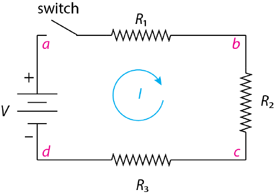
Kirchoff's first law requires that the sum of the currents at any point in the circuit is zero. Consider point b. If the current that arrives from point a is \(I\), then the current that leaves b is \(-I\), where the sign tells us about the direction of the current with respect to the point. This requires that \(I_a - I_c = 0\), which means that the current has the same absolute value at all points in the circuit.
Application of Kirchhoff's second law requires that the sum of the voltages in this circuit equal 0, which is true if the sum of the voltage across each of the three resistors is equal to the voltage of the battery. The voltage across each resistor is given by Ohm's law
\[V = IR_1 + IR_2 + IR_3 \label{series1} \]
If we divide both sides of Equation \ref{series1} by the current, then we have
\[V = I \times (R_1 + R_2 + R_3) = IR_s \label{series2} \]
where \(R_s\) is the circuit's effective resistance, which is the sum of the resistances of the individual resistors.
One of the useful properties of this circuit is that the voltage drop across an individual resistor is proportional to that resistor's contribution to \(R_s\). Consider the points in Figure \(\PageIndex{1}\) labeled \(a\) and \(b\) that are on opposite sides of the first resistor in this series. The drop in voltage across this resister, \(V_{ab}\), is
\[V_{ab} = I R_1 \label{series3} \]
Dividing Equation \ref{series3} by Equation \ref{series1}
\[\frac{V_{ab}}{V} = \frac{IR_1}{IR_s} = \frac{R_1}{R_s} \label{series4} \]
and
\[V_{ab} = V \times \frac{R_1}{R_s} \label{series5} \]
The circuit in Figure \(\PageIndex{1}\) is an example of a simple voltage divider in that it divides the battery's voltage into parts and allows us to use a single battery to select one of several possible voltages. For example, the voltage at between points a and b is
\[V_{ab} = V \times \frac{R_1}{R_s} \label{series6} \]
the voltage at between points a and c is
\[V_{ac} = V \times \frac{R_1 + R_2}{R_s} \label{series7} \]
and the voltage at between points a and d is
\[V_{ad} = V \times \frac{R_1 + R_2 + R_3}{R_s} = V \times \frac{R_s}{R_s} = V \label{series8} \]
Parallel Circuits
Figure \(\PageIndex{2}\) shows an example of a simple DC circuit in which three resistors, with resistances of R1, R2, and R3, are connected parallel to each other. A switch is included in the circuit that is used to close the loop and allow a current to flow from the battery's positive terminal to its negative terminal.
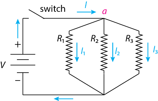
If we apply Kirchoff's first law to the current at the point identified as a, then the sum of the currents must equal zero and
\[\sum{I} = 0 = I - I_1 - I_2 - I_3 \label{parallel1} \]
where I is the current entering point a and \(I_1\), \(I_2\), and \(I_3\) are the currents passing through the three resistors. Rearranging Equation \ref{parallel1} and substituting into Ohm's law gives
\[\frac{V}{R_p} = \frac{V}{R_1} + \frac{V}{R_2} + \frac{V}{R_3} \label{parallel2} \]
where \(R_p\) is the circuit's effective resistance, which is equivalent to
\[\frac{1}{R_p} = \frac{1}{R_1} + \frac{1}{R_2} + \frac{1}{R_3} \label{parallel3} \]
or to
\[G_p = G_1 + G_2 + G_3 \label{parallel4} \]
where \(G\) is a resistor's conductance, which is the inverse of its resistance.
One of the useful properties of this circuit is that it serves as a current divider. The current passing through the resistor \(R_1\) is
\[\frac{I_1}{I} = \frac{V/R_1}{V/R_p} = \frac{1/R_1}{1/R_p} = \frac{G_1}{G_p} \label{parallel5} \]
Multiplying through by the total current gives
\[I_1 = I \times \frac{G_1}{G_p} \label{parallel6} \]
More Complex Circuits
The treatment above considers circuits that contain only resistors in series or resistors in parallel. A circuit that contains both resistors in series and resistors in parallel can often be simplified to an equivalent circuit that has only resistors in series or in parallel, or that consists of single resistor. Figure \(\PageIndex{3}\) provides an example. The circuit at the far left shows two parallel resistors, \(R_2\) and \(R_3\), that, together, are in series with a third resistor, \(R_1\).
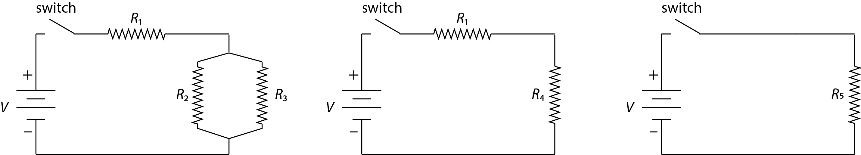
Using Equation \ref{parallel3} we can replace the two resistors in parallel with a single resistor, \(R_4\), where
\[\frac{1}{R_4} = \frac{1}{R_2} + \frac{1}{R_3} \label{complex1} \]
giving the equivalent circuit shown in the middle. Finally, we can use Equation \ref{series2} to replace the two resistors in series with the single resistor, \(R_5\), as shown on the far right, where
\[R_5 = R_1 + R_4 \label{complex2} \]
Measuring Voltage and Current
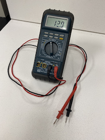
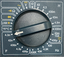
Figure \(\PageIndex{4}\) shows a digital multimeter that is used to measure voltage or current (amongst other possible measurements that we will not consider here). The measurement of voltages and currents always contains some error, the magnitude of which we consider here.
Errors in Measuring Voltage
To measure an unknown voltage of \(V_x\) with an internal resistance of \(R_x\), we include the meter with its internal resistance of \(R_m\) as part of a voltage divider circuit. We read the voltage displayed on the meter, \(V_m\), and use Equation \ref{series5} to determine \(V_x\)
\[V_m = V_x \times \frac{R_m}{R_m + R_x} \label{meter1} \]
If we do not know the value of \(R_x\), which is often the case, then we can still report an accurate value for \(V_x\) if \(R_m >> R_x\), as we can then write
\[V_m = V_x \times \frac{R_m}{R_m + R_x} \approx V_x \times \frac{R_m}{R_m} \approx V_x \label{meter2} \]
The percent error, \(E_x\), in \(V_x\)
\[E_x = \frac{V_m - V_x}{V_x} \times 100 = - \frac{R_m}{R_m + R_x} \times 100 \label{meter3} \]
For example, suppose that \(R_m = 10^3 \times R_x\), then the measurement error is
\[E = - \frac{R_x}{(10^3 \times R_x) + R_x} \times 100 = - \frac{1}{10^3 + 1} \times 100 = -0.0999\% \label{meter4} \]
or approximately –0.1%.
Errors in Measuring Current
To measure an unknown current, \(I_x\), we include the meter in a current divider circuit in which some of \(I_x\) is drawn through a load resistor, \(R_l\), of known value, and the remaining current is drawn through a known standard resistance set by the meter, \(R_m\). Using Equation \ref{parallel5} for a current divider, the fraction of \(I_x\) that passes through the meter is
\[\frac{I_m}{I_x} = \frac{R_m + R_l}{R_m} \label{meter5} \]
Solving for \(I_x\) gives
\[I_x = I_m \times \left( \frac{R_m}{R_m + R_l} \right) = I_m \times \left(1 + \frac{R_m}{R_l}\right) \label{meter6} \]
If the resistors are selected such that \(\frac{R_m}{R_l} << 1\), then the current displayed on the meter, \(I_m\), is an accurate measure of \(I_x\). The percent error in the reported current is
\[E_x = - \frac{R_m}{R_m + R_l} \times 100 \label{meter7} \]
For example, suppose that \(R_m = 10^{-3} \times R_l\), then the measurement error is
\[E = - \frac{10^{-3} \times R_l}{(10^{-3} \times R_l) + R_l} \times 100 = -\frac{10^{-3}}{10^{-3} + 1} \times 100 = -0.0999\%\label{meter8} \]
or approximately \(-0.1\%\).