21.5: Carbon Nanomaterials
- Last updated
- Save as PDF
- Page ID
- 342028
\( \newcommand{\vecs}[1]{\overset { \scriptstyle \rightharpoonup} {\mathbf{#1}} } \)
\( \newcommand{\vecd}[1]{\overset{-\!-\!\rightharpoonup}{\vphantom{a}\smash {#1}}} \)
\( \newcommand{\dsum}{\displaystyle\sum\limits} \)
\( \newcommand{\dint}{\displaystyle\int\limits} \)
\( \newcommand{\dlim}{\displaystyle\lim\limits} \)
\( \newcommand{\id}{\mathrm{id}}\) \( \newcommand{\Span}{\mathrm{span}}\)
( \newcommand{\kernel}{\mathrm{null}\,}\) \( \newcommand{\range}{\mathrm{range}\,}\)
\( \newcommand{\RealPart}{\mathrm{Re}}\) \( \newcommand{\ImaginaryPart}{\mathrm{Im}}\)
\( \newcommand{\Argument}{\mathrm{Arg}}\) \( \newcommand{\norm}[1]{\| #1 \|}\)
\( \newcommand{\inner}[2]{\langle #1, #2 \rangle}\)
\( \newcommand{\Span}{\mathrm{span}}\)
\( \newcommand{\id}{\mathrm{id}}\)
\( \newcommand{\Span}{\mathrm{span}}\)
\( \newcommand{\kernel}{\mathrm{null}\,}\)
\( \newcommand{\range}{\mathrm{range}\,}\)
\( \newcommand{\RealPart}{\mathrm{Re}}\)
\( \newcommand{\ImaginaryPart}{\mathrm{Im}}\)
\( \newcommand{\Argument}{\mathrm{Arg}}\)
\( \newcommand{\norm}[1]{\| #1 \|}\)
\( \newcommand{\inner}[2]{\langle #1, #2 \rangle}\)
\( \newcommand{\Span}{\mathrm{span}}\) \( \newcommand{\AA}{\unicode[.8,0]{x212B}}\)
\( \newcommand{\vectorA}[1]{\vec{#1}} % arrow\)
\( \newcommand{\vectorAt}[1]{\vec{\text{#1}}} % arrow\)
\( \newcommand{\vectorB}[1]{\overset { \scriptstyle \rightharpoonup} {\mathbf{#1}} } \)
\( \newcommand{\vectorC}[1]{\textbf{#1}} \)
\( \newcommand{\vectorD}[1]{\overrightarrow{#1}} \)
\( \newcommand{\vectorDt}[1]{\overrightarrow{\text{#1}}} \)
\( \newcommand{\vectE}[1]{\overset{-\!-\!\rightharpoonup}{\vphantom{a}\smash{\mathbf {#1}}}} \)
\( \newcommand{\vecs}[1]{\overset { \scriptstyle \rightharpoonup} {\mathbf{#1}} } \)
\(\newcommand{\longvect}{\overrightarrow}\)
\( \newcommand{\vecd}[1]{\overset{-\!-\!\rightharpoonup}{\vphantom{a}\smash {#1}}} \)
\(\newcommand{\avec}{\mathbf a}\) \(\newcommand{\bvec}{\mathbf b}\) \(\newcommand{\cvec}{\mathbf c}\) \(\newcommand{\dvec}{\mathbf d}\) \(\newcommand{\dtil}{\widetilde{\mathbf d}}\) \(\newcommand{\evec}{\mathbf e}\) \(\newcommand{\fvec}{\mathbf f}\) \(\newcommand{\nvec}{\mathbf n}\) \(\newcommand{\pvec}{\mathbf p}\) \(\newcommand{\qvec}{\mathbf q}\) \(\newcommand{\svec}{\mathbf s}\) \(\newcommand{\tvec}{\mathbf t}\) \(\newcommand{\uvec}{\mathbf u}\) \(\newcommand{\vvec}{\mathbf v}\) \(\newcommand{\wvec}{\mathbf w}\) \(\newcommand{\xvec}{\mathbf x}\) \(\newcommand{\yvec}{\mathbf y}\) \(\newcommand{\zvec}{\mathbf z}\) \(\newcommand{\rvec}{\mathbf r}\) \(\newcommand{\mvec}{\mathbf m}\) \(\newcommand{\zerovec}{\mathbf 0}\) \(\newcommand{\onevec}{\mathbf 1}\) \(\newcommand{\real}{\mathbb R}\) \(\newcommand{\twovec}[2]{\left[\begin{array}{r}#1 \\ #2 \end{array}\right]}\) \(\newcommand{\ctwovec}[2]{\left[\begin{array}{c}#1 \\ #2 \end{array}\right]}\) \(\newcommand{\threevec}[3]{\left[\begin{array}{r}#1 \\ #2 \\ #3 \end{array}\right]}\) \(\newcommand{\cthreevec}[3]{\left[\begin{array}{c}#1 \\ #2 \\ #3 \end{array}\right]}\) \(\newcommand{\fourvec}[4]{\left[\begin{array}{r}#1 \\ #2 \\ #3 \\ #4 \end{array}\right]}\) \(\newcommand{\cfourvec}[4]{\left[\begin{array}{c}#1 \\ #2 \\ #3 \\ #4 \end{array}\right]}\) \(\newcommand{\fivevec}[5]{\left[\begin{array}{r}#1 \\ #2 \\ #3 \\ #4 \\ #5 \\ \end{array}\right]}\) \(\newcommand{\cfivevec}[5]{\left[\begin{array}{c}#1 \\ #2 \\ #3 \\ #4 \\ #5 \\ \end{array}\right]}\) \(\newcommand{\mattwo}[4]{\left[\begin{array}{rr}#1 \amp #2 \\ #3 \amp #4 \\ \end{array}\right]}\) \(\newcommand{\laspan}[1]{\text{Span}\{#1\}}\) \(\newcommand{\bcal}{\cal B}\) \(\newcommand{\ccal}{\cal C}\) \(\newcommand{\scal}{\cal S}\) \(\newcommand{\wcal}{\cal W}\) \(\newcommand{\ecal}{\cal E}\) \(\newcommand{\coords}[2]{\left\{#1\right\}_{#2}}\) \(\newcommand{\gray}[1]{\color{gray}{#1}}\) \(\newcommand{\lgray}[1]{\color{lightgray}{#1}}\) \(\newcommand{\rank}{\operatorname{rank}}\) \(\newcommand{\row}{\text{Row}}\) \(\newcommand{\col}{\text{Col}}\) \(\renewcommand{\row}{\text{Row}}\) \(\newcommand{\nul}{\text{Nul}}\) \(\newcommand{\var}{\text{Var}}\) \(\newcommand{\corr}{\text{corr}}\) \(\newcommand{\len}[1]{\left|#1\right|}\) \(\newcommand{\bbar}{\overline{\bvec}}\) \(\newcommand{\bhat}{\widehat{\bvec}}\) \(\newcommand{\bperp}{\bvec^\perp}\) \(\newcommand{\xhat}{\widehat{\xvec}}\) \(\newcommand{\vhat}{\widehat{\vvec}}\) \(\newcommand{\uhat}{\widehat{\uvec}}\) \(\newcommand{\what}{\widehat{\wvec}}\) \(\newcommand{\Sighat}{\widehat{\Sigma}}\) \(\newcommand{\lt}{<}\) \(\newcommand{\gt}{>}\) \(\newcommand{\amp}{&}\) \(\definecolor{fillinmathshade}{gray}{0.9}\)Fullerenes and Nanotubes
Introduction
Although nanomaterials had been known for many years prior to the report of C60 the field of nanoscale science was undoubtedly founded upon this seminal discovery. Part of the reason for this explosion in nanochemistry is that while carbon materials range from well-defined nano sized molecules (i.e., C60) to tubes with lengths of hundreds of microns, they do not exhibit the instabilities of other nanomaterials as a result of the very high activation barriers to their structural rearrangement. As a consequence they are highly stable even in their unfunctionalized forms. Despite this range of carbon nanomaterials possible they exhibit common reaction chemistry: that of organic chemistry.
The previously unknown allotrope of carbon: C60, was discovered in 1985, and in 1996, Curl, Kroto, and Smalley were awarded the Nobel Prize in Chemistry for the discovery. The other allotropes of carbon are graphite (sp2) and diamond (sp3). C60, commonly known as the “buckyball” or “Buckminsterfullerene”, has a spherical shape comprising of highly pyramidalized sp2 carbon atoms. The C60 variant is often compared to the typical soccer football, hence buckyball. However, confusingly, this term is commonly used for higher derivatives. Fullerenes are similar in sheet structure to graphite but they contain pentagonal (or sometimes heptagonal) rings that prevent the sheet from being planar. The unusual structure of C60 led to the introduction of a new class of molecules known as fullerenes, which now constitute the third allotrope of carbon. Fullerenes are commonly defined as “any of a class of closed hollow aromatic carbon compounds that are made up of twelve pentagonal and differing numbers of hexagonal faces.”
The number of carbon atoms in a fullerene range from C60 to C70, C76, and higher. Higher order fullerenes include carbon nanotubes that can be described as fullerenes that have been stretched along a rotational axis to form a tube. As a consequence of differences in the chemistry of fullerenes such as C60 and C70 as compared to nanotubes, these will be dealt with separately herein. In addition there have also been reports of nanohorns and nanofibers, however, these may be considered as variations on the general theme. It should be noted that fullerenes and nanotubes have been shown to be in flames produced by hydrocarbon combustion. Unfortunately, these naturally occurring varieties can be highly irregular in size and quality, as well as being formed in mixtures, making them unsuitable for both research and industrial applications.
Fullerenes
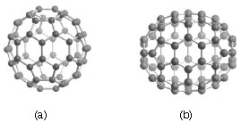
Carbon-60 (C60) is probably the most studied individual type of nanomaterial. The spherical shape of C60 is constructed from twelve pentagons and twenty hexagons and resembles a soccer ball (Figure \(\PageIndex{1}\)a). The next stable higher fullerene is C70 (Figure \(\PageIndex{1}\)b) that is shaped like a rugby or American football. The progression of higher fullerenes continues in the sequence C74, C76, C78, etc. The structural relationship between each involves the addition of six membered rings. Mathematically (and chemically) two principles define the existence of a stable fullerene, i.e., Euler’s theorem and isolated pentagon rule (IPR). Euler’s theorem states that for the closure of each spherical network, n (n ≥ 2) hexagons and 12 pentagons are required while the IPR says no two pentagons may be connected directly with each other as destabilization is caused by two adjacent pentagons.
Although fullerenes are composed of sp2 carbons in a similar manner to graphite, fullerenes are soluble in various common organic solvents. Due to their hydrophobic nature, fullerenes are most soluble in CS2 (C60 = 7.9 mg/mL) and toluene (C60 = 2.8 mg/mL). Although fullerenes have a conjugated system, their aromaticity is distinctive from benzene that has all C-C bonds of equal lengths, in fullerenes two distinct classes of bonds exist. The shorter bonds are at the junctions of two hexagons ([6, 6] bonds) and the longer bonds at the junctions of a hexagon and a pentagon ([5,6] bonds). This difference in bonding is responsible for some of the observed reactivity of fullerenes.
Synthesis of fullerenes
The first observation of fullerenes was in molecular beam experiments at Rice University. Subsequent studies demonstrated that C60 it was relatively easy to produce grams of fullerenes. Although the synthesis is relatively straightforward fullerene purification remains a challenge and determines fullerene’s commercial price. The first method of production of measurable quantities of fullerenes used laser vaporization of carbon in an inert atmosphere, but this produced microscopic amounts of fullerenes. Laboratory scales of fullerene are prepared by the vaporization of carbon rods in a helium atmosphere. Commercial production ordinarily employs a simple ac or dc arc. The fullerenes in the black soot collected are extracted in toluene and purified by liquid chromatography. The magenta C60 comes off the column first, followed by the red C70, and other higher fullerenes. Even though the mechanism of a carbon arc differs from that of a resistively heated carbon rod (because it involves a plasma) the He pressure for optimum C60 formation is very similar.
A ratio between the mass of fullerenes and the total mass of carbon soot defines fullerene yield. The yields determined by UV-Vis absorption are approximately 40%, 10-15%, and 15% in laser, electric arc, and solar processes. Interestingly, the laser ablation technique has both the highest yield and the lowest productivity and, therefore, a scale-up to a higher power is costly. Thus, fullerene commercial production is a challenging task. The world's first computer controlled fullerene production plant is now operational at the MER Corporation, who pioneered the first commercial production of fullerene and fullerene products.
Endohedral fullerenes
Endohedral fullerenes are fullerenes that have incorporated in their inner sphere atoms, ions or clusters. Endohedral fullerenes are generally divided into two groups: endohedral metallofullerenes and non-metal doped fullerenes. The first endohedral metallofullerenes was called La@C60. The @ sign in the name reflects the notion of a small molecule trapped inside a shell.
Doping fullerenes with metals takes place in-situ during the fullerene synthesis in an arc reactor or via laser evaporation. A wide range of metals have been encased inside a fullerene, i.e., Sc, Y, La, Ce, Ba, Sr, K, U, Zr, and Hf. Unfortunately, the synthesis of endohedral metallofullerenes is unspecific because in addition a high yield of unfilled fullerenes, compounds with different cage sizes are prepared (e.g., La@C60 or La@C82). A characteristic of endohedral metallofullerenes is that electrons will transfer from the metal atom to the fullerene cage and that the metal atom takes a position off-center in the cage. The size of the charge transfer is not always simple to determine, but it is usually between 2 and 3 units (e.g., La2@C80) but can be as high as 6 electrons (e.g., Sc3N@C80). These anionic fullerene cages are very stable molecules and do not have the reactivity associated with ordinary empty fullerenes (see below). This lack of reactivity is utilized in a method to purify endohedral metallofullerenes from empty fullerenes.
The endohedral He@C60 and Ne@C60 form when C60 is exposed to a pressure of around 3 bar of the appropriate noble gases. Under these conditions it was possible to dope 1 in every 650,000 C60 cages with a helium atom. Endohedral complexes with He, Ne, Ar, Kr and Xe as well as numerous adducts of the He@C60 compound have also been proven with operating pressures of 3000 bars and incorporation of up to 0.1 % of the noble gases. The isolation of N@C60, N@C70 and P@C60 is very unusual and unlike the metal derivatives no charge transfer of the pnictide atom in the center to the carbon atoms of the cage takes place.
Chemically functionalized fullerenes
Although fullerenes have a conjugated aromatic system all the carbons are quaternary (i.e., containing no hydrogen), which results in making many of the characteristic substitution reactions of planar aromatics impossible. Thus, only two types of chemical transformations exist: redox reactions and addition reactions. Of these, addition reactions have the largest synthetic value. Another remarkable feature of fullerene addition chemistry is the thermodymics of the process. Since the sp2 carbon atoms in a fullerene are paramidalized there is significant strain energy. For example, the strain energy in C60 is ca 8 kcal/mol, which is 80% of its heat of formation. So the relief of this strain energy leading to sp3 hybridized C atoms is the major driving force for addition reactions (Figure \(\PageIndex{2}\)). As a consequence, most additions to fullerenes are exothermic reactions.

Cyclic voltammetry (CV) studies show that C60 can be reduced and oxidized reversibly up to 6 electrons with one-electron transfer processes. Fulleride anions can be generated by electrochemical method and then be used to synthesize covalent organofullerene derivatives. Alkali metals can chemically reduce fullerene in solution and solid state to form MxC60 (x = 3 - 6). C60 can also be reduced by less electropositive metals like mercury to form C60- and C602-. In addition, salts can also be synthesized with organic molecules, for example [TDAE+][C60-] possesses interesting electronic and magnetic behavior.
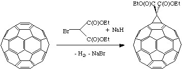
Geometric and electronic analysis predicted that fullerene behaves live an electro-poor conjugated polyolefin. Indeed C60 and C70 undergo a range of nucleophilic reactions with carbon, nitrogen, phosphorous and oxygen nucleophiles. C60 reacts readily with organolithium and Grignard compounds to form alkyl, phenyl or alkanyl fullerenes. Possibly the most widely used additions to fullerene is the Bingel reaction (Figure \(\PageIndex{3}\)), where a carbon nucleophile, generated by deprotonation of α-halo malonate esters or ketones, is added to form a cyclopropanation product. The α-halo esters and ketones can also be generated in situ with I2 or CBr4 and a weak base as 1,8-diazabicyclo[5.4.0]unde-7ene (DBU). The Bingel reaction is considered one of the most versatile and efficient methods to functionalize C60.
Cycloaddition is another powerful tool to functionalize fullerenes, in particular because of its selectivity with the 6,6 bonds, limiting the possible isomers (Figure \(\PageIndex{4}\)). The dienophilic feature of the [6,6] double bonds of C60 enables the molecule to undergo various cycloaddition reactions in which the monoadducts can be generated in high yields. The best studies cycloadditon reactions of fullerene are [3+2] additions with diazoderivatives and azomethine ylides (Prato reactions). In this reaction, azomethine ylides can be generated in situ from condensation of α-amino acids with aldehydes or ketones, which produce 1,3 dipoles to further react with C60 in good yields (Figure \(\PageIndex{5}\)). Hundreds of useful building blocks have been generated by those two methods. The Prato reactions have also been successfully applied to carbon nanotubes.


The oxidation of fullerenes, such as C60, has been of increasing interest with regard to applications in photoelectric devices, biological systems, and possible remediation of fullerenes. The oxidation of C60 to C60On (n = 1, 2) may be accomplished by photooxidation, ozonolysis, and epoxidation. With each of these methods, there is a limit to the isolable oxygenated product, C60On with n < 3. Highly oxygenated fullerenes, C60On with 3 ≤ n ≤ 9, have been prepared by the catalytic oxidation of C60 with ReMeO3/H2O2.
Carbon nanotubes
A key breakthrough in carbon nanochemistry came in 1993 with the report of needle-like tubes made exclusively of carbon. This material became known as carbon nanotubes (CNTs). There are several types of nanotubes. The first discovery was of multi walled tubes (MWNTs) resembling many pipes nested within each other. Shortly after MWNTs were discovered single walled nanotubes (SWNTs) were observed. Single walled tubes resemble a single pipe that is potentially capped at each end. The properties of single walled and multi walled tubes are generally the same, although single walled tubes are believed to have superior mechanical strength and thermal and electrical conductivity; it is also more difficult to manufacture them.
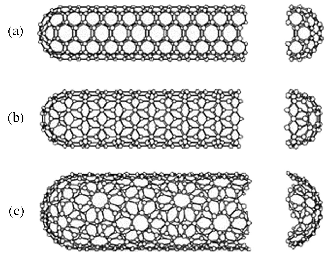
Single walled carbon nanotubes (SWNTs) are by definition fullerene materials. Their structure consists of a graphene sheet rolled into a tube and capped by half a fullerene (Figure \(\PageIndex{6}\)). The carbon atoms in a SWNT, like those in a fullerene, are sp2 hybridized. The structure of a nanotube is analogous to taking this graphene sheet and rolling it into a seamless cylinder. The different types of SWNTs are defined by their diameter and chirality. Most of the presently used single-wall carbon nanotubes have been synthesized by the pulsed laser vaporization method, however, increasingly SWNTs are prepared by vapor liquid solid catalyzed growth.
The physical properties of SWNTs have made them an extremely attractive material for the manufacturing of nano devices. SWNTs have been shown to be stronger than steel as estimates for the Young’s modulus approaches 1 Tpa. Their electrical conductance is comparable to copper with anticipate current densities of up to 1013 A/cm2 and a resistivity as low as 0.34 x 10⁻⁴ Ω.cm at room temperatures. Finally, they have a high thermal conductivity (3000 - 6000 W.m/K).
The electronic properties of a particular SWNT structure are based on its chirality or twist in the structure of the tube which is defined by its n,m value. The values of n and m determine the chirality, or "twist" of the nanotube. The chirality in turn affects the conductance of the nanotube, its density, its lattice structure, and other properties. A SWNT is considered metallic if the value n-m is divisible by three. Otherwise, the nanotube is semi-conducting. The external environment also has an effect on the conductance of a tube, thus molecules such as O2 and NH3 can change the overall conductance of a tube, while the presence of metals have been shown to significantly effect the opto-electronic properties of SWNTs.
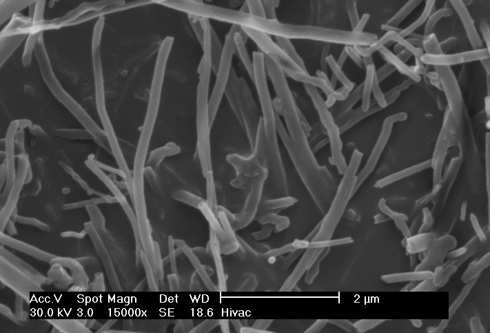
Multi walled carbon nanotubes (MWNTs) range from double walled NTs, through many-walled NTs (Figure \(\PageIndex{7}\)) to carbon nanofibers. Carbon nanofibers are the extreme of multi walled tubes (Figure \(\PageIndex{8}\)) and they are thicker and longer than either SWNTs or MWNTs, having a cross-sectional of ca. 500 Å2 and are between 10 to 100 μm in length. They have been used extensively in the construction of high strength composites.

Synthesis of carbon nanotubes
A range of methodologies have been developed to produce nanotubes in sizeable quantities, including arc discharge, laser ablation, high pressure carbon monoxide (HiPco), and vapor liquid solid (VLS) growth. All these processes take place in vacuum or at low pressure with a process gases, although VLS growth can take place at atmospheric pressure. Large quantities of nanotubes can be synthesized by these methods; advances in catalysis and continuous growth processes are making SWNTs more commercially viable.
The first observation of nanotubes was in the carbon soot formed during the arc discharge production of fullerenes. The high temperatures caused by the discharge caused the carbon contained in the negative electrode to sublime and the CNTs are deposited on the opposing electrode. Tubes produced by this method were initially multi walled tubes (MWNTs). However, with the addition of cobalt to the vaporized carbon, it is possible to grow single walled nanotubes. This method it produces a mixture of components, and requires further purification to separate the CNTs from the soot and the residual catalytic metals. Producing CNTs in high yield depends on the uniformity of the plasma arc, and the temperature of the deposit forming on the carbon electrode.
Higher yield and purity of SWNTs may be prepared by the use of a dual-pulsed laser. SWNTs can be grown in a 50% yield through direct vaporization of a Co/Ni doped graphite rod with a high-powered laser in a tube furnace operating at 1200 °C. The material produced by this method appears as a mat of “ropes”, 10 - 20 nm in diameter and up to 100 μm or more in length. Each rope consists of a bundle of SWNTs, aligned along a common axis. By varying the process parameters such as catalyst composition and the growth temperature, the average nanotube diameter and size distribution can be varied. Although arc-discharge and laser vaporization are currently the principal methods for obtaining small quantities of high quality SWNTs, both methods suffer from drawbacks. The first is that they involve evaporating the carbon source, making scale-up on an industrial level difficult and energetically expensive. The second issue relates to the fact that vaporization methods grow SWNTs in highly tangled forms, mixed with unwanted forms of carbon and/or metal species. The SWNTs thus produced are difficult to purify, manipulate, and assemble for building nanotube-device architectures for practical applications.
In order to overcome some of the difficulties of these high-energy processes, the chemical catalysis method was developed in which a hydrocarbon feedstock is used in combination with a metal catalyst. The catalyst is typically, but not limited to iron, colbalt, or iron/molybdenum, it is heated under reducing conditions in the presence of a suitable carbon feedstock, e.g., ethylene. This method can be used for both SWNTs and MWNTs; the formation of each is controlled by the identity of the catalyst and the reaction conditions. A convenient laboratory scale apparatus is available from Nanotech Innovations, Inc., for the synthesis of highly uniform, consistent, research sample that uses pre-weighed catalyst/carbon source ampoules. This system, allows for 200 mg samples of MWNTs to be prepared for research and testing. The use of CO as a feedstock, in place of a hydrocarbon, led to the development of the high-pressure carbon monoxide (HiPco) procedure for SWNT synthesis. By this method, it is possible to produce gram quantities of SWNTs, unfortunately, efforts to scale beyond that have not met with complete success.
Initially developed for small-scale investigations of catalyst activity, vapor liquid solid (VLS) growth of nanotubes has been highly studied, and now shows promise for large-scale production of nanotubes. Recent approaches have involved the use of well-defined nanoparticle or molecular precursors and many different transition metals have been employed, but iron, nickel, and cobalt remain to be the focus of most research. The nanotubes grow at the sites of the metal catalyst; the carbon-containing gas is broken apart at the surface of the catalyst particle, and the carbon is transported to the edges of the particle, where it forms the nanotube. The length of the tube grown in surface supported catalyst VLS systems appears to be dependent on the orientation of the growing tube with the surface. By properly adjusting the surface concentration and aggregation of the catalyst particles it is possible to synthesize vertically aligned carbon nanotubes, i.e., as a carpet perpendicular to the substrate.
Of the various means for nanotube synthesis, the chemical processes show the greatest promise for industrial scale deposition in terms of its price/unit ratio. There are additional advantages to the VLS growth, which unlike the other methods is capable of growing nanotubes directly on a desired substrate. The growth sites are controllable by careful deposition of the catalyst. Additionally, no other growth methods have been developed to produce vertically aligned SWNTs.
Chemical functionalization of carbon nanotubes
The limitation of using carbon nanotubes in any practical applications has been its solubility; for example SWNTs have little to no solubility in most solvent due to the aggregation of the tubes. Aggregation/roping of nanotubes occurs as a result of the high van der Waals binding energy of ca. 500 eV per mm of tube contact. The van der Waals force between the tubes is so great, that it take tremendous energy to pry them apart, making it very to make combination of nanotubes with other materials such as in composite applications. The functionalization of nanotubes, i.e., the attachment of “chemical functional groups” provides the path to overcome these barriers. Functionalization can improve solubility as well as processibility, and has been used to align the properties of nanotubes to those of other materials. The clearest example of this is the ability to solubilize nanotubes in a variety of solvents, including water. It is important when discussing functionalization that a distinction is made between covalent and non-covalent functionalization.
Current methods for solubilizing nanotubes without covalent functionalization include highly aromatic solvents, super acids, polymers, or surfactants. Non-covalent “functionalization” is generally on the concept of supramolecular interactions between the SWNT and some macromolecule as a result of various adsorption forces, such as van der Waals’ and π-stacking interactions. The chemical speciation of the nanotube itself is not altered as a result of the interaction. In contrast, covalent functionalization relies on the chemical reaction at either the sidewall or end of the SWNT. As may be expected the high aspect ratio of nanotubes means that sidewall functionalization is much more important than the functionalization of the cap. Direct covalent sidewall functionalization is associated with a change of hybridization from sp2 to sp2 and a simultaneous loss of conjugation. An alternative approach to covalent functionalization involves the reaction of defects present (or generated) in the structure of the nanotube. Defect sites can be the open ends and holes in the sidewalls, and pentagon and heptagon irregularities in the hexagon graphene framework (often associated with bends in the tubes). All these functionalizations are exohedral derivatizations. Taking the hollow structure of nanotubes into consideration, endohedral functionalization of SWNTs is possible, i.e., the filling of the tubes with atoms or small molecules. It is important to note that covalent functionalization methods have one problem in common: extensive covalent functionalization modifies SWNT properties by disrupting the continuous π–system of SWNTs.
Various applications of nanotubes require different, specific modification to achieve desirable physical and chemical properties of nanotubes. In this regard, covalent functionalization provides a higher degree of fine-tuning the chemistry and physics of SWNTs than non-covalent functionalization. Until now, a variety of methods have been used to achieve the functionalization of nanotubes (Figure \(\PageIndex{9}\)).
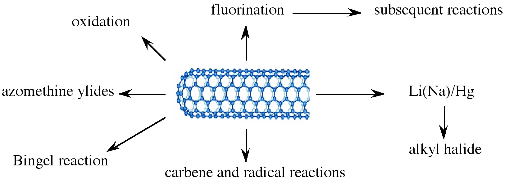
Taking chemistry developed for C60, SWNTs may be functionalized using 1,3 dipolar addition of azomethine ylides. The functionalized SWNTs are soluble in most common organic solvents. The azomethine ylide functionalization method was also used for the purification of SWNTs. Under electrochemical conditions, aryl diazonium salts react with SWNTs to achieve functionalized SWNTs, alternatively the diazonium ions may be generated in-situ from the corresponding aniline, while a solvent free reaction provides the best chance for large-scale functionalization this way. In each of these methods it is possible to control the amount of functionalization on the tube by varying reaction times and the reagents used; functionalization as high as 1 group per every 10 - 25 carbon atoms is possible.
Organic functionalization through the use of alkyl halides, a radical pathway, on tubes treated with lithium in liquid ammonia offers a simple and flexible route to a range of functional groups. In this reaction, functionalization occurs on every 17 carbons. Most success has been found when the tubes are dodecylated. These tubes are soluble in chloroform, DMF, and THF.
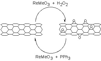
The addition of oxygen moieties to SWNT sidewalls can be achieved by treatment with acid or wet air oxidation, and ozonolysis. The direct epoxidation of SWNTs may be accomplished by the direct reaction with a peroxide reagent, or catalytically. Catalytic de-epoxidation (Figure \(\PageIndex{10}\)) allows for the quantitative analysis of sidewall epoxide and led to the surprising result that previously assumed “pure” SWNTs actually contain ca. 1 oxygen per 250 carbon atoms.
One of the easiest functionalization routes, and a useful synthon for subsequent conversions, is the fluorination of SWNTs, using elemental fluorine. Importantly, a C:F ratios of up to 2:1 can be achieved without disruption of the tubular structure. The fluorinated SWNTs (F-SWNTs) proved to be much more soluble than pristine SWNTs in alcohols (1 mg/mL in iso-propanol), DMF and other selected organic solvents. Scanning tunneling microscopy (STM) revealed that the fluorine formed bands of approximately 20 nm, while calculations using DFT revealed 1,2 addition is more energetically preferable than 1,4 addition, which has been confirmed by solid state 13C NMR. F-SWNTs make highly flexible synthons and subsequent elaboration has been performed with organo lithium, Grignard reagents, and amines.
Functionalized nanotubes can be characterized by a variety of techniques, such as atomic force microscopy (AFM), transmission electron microscopy (TEM), UV-vis spectroscopy, and Raman spectroscopy. Changes in the Raman spectrum of a nanotube sample can indicate if functionalization has occurred. Pristine tubes exhibit two distinct bands. They are the radial breathing mode (230 cm-1) and the tangential mode (1590 cm-1). When functionalized, a new band, called the disorder band, appears at ca.1350 cm-1. This band is attributed to sp3-hybridized carbons in the tube. Unfortunately, while the presence of a significant D mode is consistent with sidewall functionalization and the relative intensity of D (disorder) mode versus the tangential G mode (1550 – 1600 cm-1) is often used as a measure of the level of substitution. However, it has been shown that Raman is an unreliable method for determination of the extent of functionalization since the relative intensity of the D band is also a function of the substituents distribution as well as concentration. Recent studies suggest that solid state 13C NMR are possibly the only definitive method of demonstrating covalent attachment of particular functional groups.
Coating carbon nanotubes: creating inorganic nanostructures
Fullerenes, nanotubes and nanofibers represent suitable substrates for the seeding other materials such as oxides and other minerals, as well as semiconductors. In this regard, the carbon nanomaterial acts as a seed point for the growth as well as a method of defining unusual aspect ratios. For example, silica fibers can be prepared by a number of methods, but it is only through coating SWNTs that silica nano-fibers with of micron lengths with tens of nanometers in diameter may be prepared.
While C60 itself does not readily seed the growth of inorganic materials, liquid phase deposition of oxides, such as silica, in the presence of fullerenol, C60(OH)n, results in the formation of uniform oxide spheres. It appears the fullerenol acts as both a reagent and a physical point for subsequent oxide growth, and it is C60, or an aggregate of C60, that is present within the spherical particle. The addition of fullerenol alters the morphology and crystal phase of CaCO3 precipitates from aqueous solution, resulting in the formation of spherical features, 5-pointed flower shaped clusters, and triangular crystals as opposed to the usual rhombic crystals. In addition, the meta-stable vaterite phase is observed with the addition of C60(OH)n.
As noted above individual SWNTs may be obtained in solution when encased in a cylindrical micelle of a suitable surfactant. These individualized nanotubes can be coated with a range of inorganic materials. Liquid phase deposition (LPD) appears to have significant advantages over other methods such as incorporating surfacted SWNTs into a preceramic matrix, in situ growth of the SWNT in an oxide matrix, and sol-gel methods. The primary advantage of LPD growth is that individual SWNTs may be coated rather than bundles or ropes. For example, SWNTs have been coated with silica by liquid phase deposition (LPD) using a silica/H2SiF6 solution and a surfactant-stabilized solution of SWNTs. The thickness of the coating is dependent on the reaction mixture concentration and the reaction time. The SWNT core can be removed by thermolysis under oxidizing conditions to leave a silica nano fiber. It is interesting to note that the use of a surfactant is counter productive when using MWNTs and VGFs, in this case surface activation of the nanotube offers the suitable growth initiation. Pre-oxidation of the MWNT or VGF allows for uniform coatings to be deposited. The coated SWNTs, MWNTs, and VGFs can be subsequently reacted with suitable surface reagents to impart miscibility in aqueous solutions, guar gels, and organic matrixes. In addition to simple oxides, coated nanotubes have been prepared with minerals such as carbonates and semiconductors.
Bibliography
- S. M. Bachilo, M. S. Strano, C. Kittrell, R. H. Hauge, R. E. Smalley, and R. B. Weisman, Science, 2002, 298, 2361.
- D. S. Bethune, C. H. Klang, M. S. deVries, G. Gorman, R. Savoy, J. Vazquez, and R. Beyers, Nature, 1993, 363, 605.
- J, J. Brege, C. Gallaway, and A. R. Barron, J. Phys. Chem., C, 2007, 111, 17812.
- C. A. Dyke and J. M. Tour, J. Am. Chem. Soc., 2003, 125, 1156.
- Z. Ge, J. C. Duchamp, T. Cai, H. W. Gibson, and H. C. Dorn, J. Am. Chem. Soc., 2005, 127, 16292.
- L. A. Girifalco, M. Hodak, and R. S. Lee, Phys. Rev. B, 2000, 62, 13104.
- T. Guo, P. Nikolaev, A. G. Rinzler, D. Tománek, D. T. Colbert, and R. E. Smalley, J. Phys. Chem., 1995, 99, 10694.
- J. H. Hafner, M. J. Bronikowski, B. R. Azamian, P. Nikolaev, A. G. Rinzler, D. T. Colbert, K. A. Smith, and R. E. Smalley, Chem. Phys. Lett., 1998, 296, 195.
- A. Hirsch, Angew. Chem. Int. Ed., 2002, 40, 4002.
- S. Iijima and T. Ichihashi, Nature, 1993, 363, 603.
- H. R. Jafry, E. A. Whitsitt, and A. R. Barron, J. Mater. Sci., 2007, 42, 7381.
- H. W. Kroto, J. R. Heath, S. C. O’Brien, R. F. Curl, and R. E. Smalley, Nature, 1985, 318, 162.
- F. Liang, A. K. Sadana, A. Peera, J. Chattopadhyay, Z. Gu, R. H. Hauge, and W. E. Billups, Nano Lett., 2004, 4, 1257.
- D. Ogrin and A. R. Barron, J. Mol. Cat. A: Chem., 2006, 244, 267.
- D. Ogrin, J. Chattopadhyay, A. K. Sadana, E. Billups, and A. R. Barron, J. Am. Chem. Soc., 2006, 128, 11322.
- R. E. Smalley, Acc. Chem. Res., 1992, 25, 98.
- M. M. J. Treacy, T. W. Ebbesen, and J. M. Gibson, Nature, 1996, 381, 678.
- E. A. Whitsitt and A. R. Barron, Nano Lett., 2003, 3, 775.
- J. Yang and A. R. Barron, Chem. Commun., 2004, 2884.
- L. Zeng, L. B. Alemany, C. L. Edwards, and A. R. Barron, Nano Res., 2008, 1, 72.
Graphene
Introduction
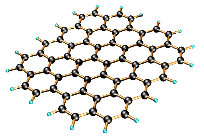
Graphene is a one-atom-thick planar sheet of sp2-bonded carbon atoms that are densely packed in a honeycomb crystal lattice (Figure \(\PageIndex{11}\)). The name comes from “graphite” and “alkene”; graphite itself consists of many graphene sheets stacked together.
Single-layer graphene nanosheets were first characterized in 2004, prepared by mechanical exfoliation (the “scotch-tape” method) of bulk graphite. Later graphene was produced by epitaxial chemical vapor deposition on silicon carbide and nickel substrates. Most recently, graphene nanoribbons (GNRs) have been prepared by the oxidative treatment of carbon nanotubes and by plasma etching of nanotubes embedded in polymer films.
Physical properties of graphene
Graphene has been reported to have a Young’s modulus of 1 TPa and intrinsic strength of 130 GP; similar to single walled carbon nanotubes (SWNTs). The electronic properties of graphene also have some similarity with carbon nanotubes. Graphene is a zero-bandgap semiconductor. Electron mobility in graphene is extraordinarily high (15,000 cm2/V.s at room temperature) and ballistic electron transport is reported to be on length scales comparable to that of SWNTs. One of the most promising aspects of graphene involves the use of GNRs. Cutting an individual graphene layer into a long strip can yield semiconducting materials where the bandgap is tuned by the width of the ribbon.
While graphene’s novel electronic and physical properties guarantee this material will be studied for years to come, there are some fundamental obstacles yet to overcome before graphene based materials can be fully utilized. The aforementioned methods of graphene preparation are effective; however, they are impractical for large-scale manufacturing. The most plentiful and inexpensive source of graphene is bulk graphite. Chemical methods for exfoliation of graphene from graphite provide the most realistic and scalable approach to graphene materials.
Graphene layers are held together in graphite by enormous van der Waals forces. Overcoming these forces is the major obstacle to graphite exfoliation. To date, chemical efforts at graphite exfoliation have been focused primarily on intercalation, chemical derivatization, thermal expansion, oxidation-reduction, the use of surfactants, or some combination of these.
Graphite oxide
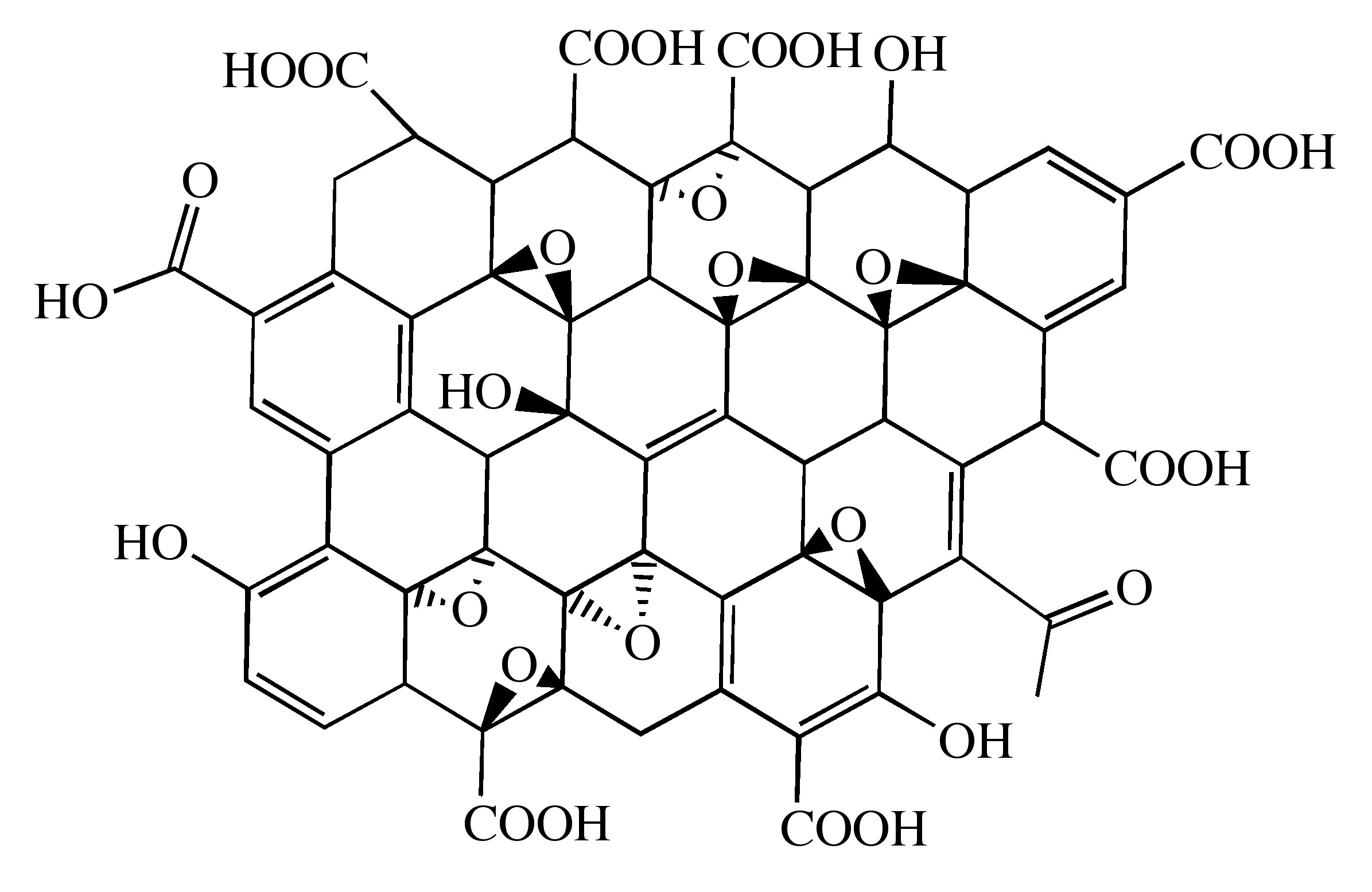
Probably the most common route to graphene involves the production of graphite oxide (GO) by extremely harsh oxidation chemistry. The methods of Staudenmeier or Hummers are most commonly used to produce GO, a highly exfoliated material that is dispersible in water. The structure of GO has been the subject of numerous studies; it is known to contain epoxide functional groups along the basal plane of sheets as well as hydroxyl and carboxyl moieties along the edges (Figure \(\PageIndex{12}\)). In contrast to other methods for the synthesis of GO, the the m-peroxybenzoic acid (m-CPBA) oxidation of microcrystalline synthetic graphite at room temperature yields graphite epoxide in high yield, without significant additional defects.
As graphite oxide is electrically insulating, it must be converted by chemical reduction to restore the electronic properties of graphene. Chemically converted graphene (CCG) is typically reduced by hydrazine or borohydride. The properties of CCG can never fully match those of graphene for two reasons:
- Oxidation to GO introduces defects.
- Chemical reduction does not fully restore the graphitic structure.
As would be expected, CCG is prone to aggregation unless stabilized. Graphene materials produced from pristine graphite avoid harsh oxidation to GO and subsequent (incomplete) reduction; thus, materials produced are potentially much better suited to electronics applications.
A catalytic approach to the removal of epoxides from fullerenes and SWNTs has been applied to graphene epoxide and GO. Treatment of oxidized graphenes with methyltrioxorhenium (MeReO3, MTO) in the presence of PPh3 results in the oxygen transfer, to form O=PPh3 and allow for quantification of the C:O ratio.
Homogeneous graphene dispersions
An alternate approach to producing graphene materials involves the use of pristine graphite as starting material. The fundamental value of such an approach lies in its avoidance of oxidation to GO and subsequent (incomplete) reduction, thereby preserving the desirable electronic properties of graphene. There is precedent for exfoliation of pristine graphite in neat organic solvents without oxidation or surfactants. It has been reported that N,N-dimethylformamide (DMF) dispersions of graphene are possible, but no detailed characterization of the dispersions were reported. In contrast, Coleman and coworkers reported similar dispersions using N-methylpyrrolidone (NMP), resulting in individual sheets of graphene at a concentration of ≤0.01 mg/mL. NMP and DMF are highly polar solvents, and not ideal in cases where reaction chemistry requires a nonpolar medium. Further, they are hygroscopic, making their use problematic when water must be excluded from reaction mixtures. Finally, DMF is prone to thermal and chemical decomposition.
Recently, dispersions of graphene has been reported in ortho-dichlorobenzene (ODCB) using a wide range of graphite sources. The choice of ODCB for graphite exfoliation was based on several criteria:
- ODCB is a common reaction solvent for fullerenes and is known to form stable SWNT dispersions.
- ODCB is a convenient high-boiling aromatic, and is compatible with a variety of reaction chemistries.
- ODCB, being aromatic, is able to interact with graphene via π-π stacking.
- It has been suggested that good solvents for graphite exfoliation should have surface tension values of 40 – 50 mJ/m2. ODCB has a surface tension of 36.6 mJ/m2, close to the proposed range.
Graphite is readily exfoliated in ODCB with homogenization and sonication. Three starting materials were successfully dispersed: microcrystalline synthetic, thermally expanded, and highly ordered pyrolytic graphite (HOPG). Dispersions of microcrystalline synthetic graphite have a concentration of 0.03 mg/mL, determined gravimetrically. Dispersions from expanded graphite and HOPG are less concentrated (0.02 mg/mL).
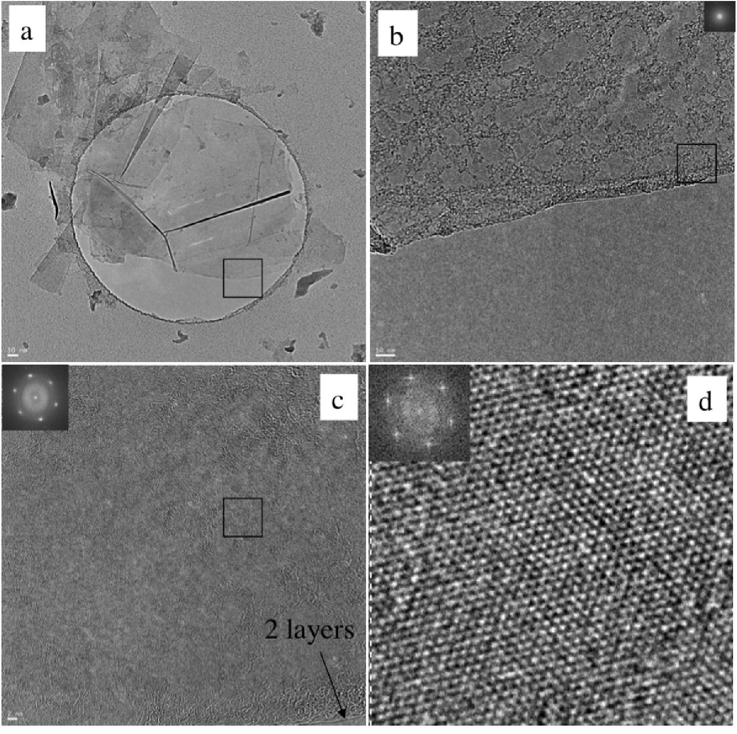
High resolution transmission electron microscopy (HRTEM) shows mostly few-layer graphene (n < 5) with single layers and small flakes stacked on top (Figure \(\PageIndex{13}\)). Large graphitic domains are visible; this is further supported by selected area electron diffraction (SAED) and fast Fourier transform (FFT) in selected areas. Atomic force microscope (AFM) images of dispersions sprayed onto silicon substrates shows extremely thin flakes with nearly all below 10 nm. Average height is 7 - 10 nm. The thinnest are less than 1 nm, graphene monolayers. Lateral dimensions of nanosheets range from 100 – 500 nm.
As-deposited films cast from ODCB graphene show poor electrical conductivity, however, after vacuum annealing at 400 °C for 12 hours the films improve vastly, having sheet resistances on the order of 60 Ω/sq. By comparison, graphene epitaxially grown on Ni has a reported sheet resistance of 280 Ω/sq.
Covalent functionalization of graphene and graphite oxide
The covalent functionalization of SWNTs is well established. Some routes to covalently functionalized SWNTs include esterification/ amidation, reductive alkylation (Billups reaction), and treatment with azomethine ylides (Prato reaction), diazonium salts, or nitrenes. Conversely, the chemical derivatization of graphene and GO is still relatively unexplored.
Some methods previously demonstrated for SWNTs have been adapted to GO or graphene. GO carboxylic acid groups have been converted into acyl chlorides followed by amidation with long-chain amines. Additionally, the coupling of primary amines and amino acids via nucleophilic attack of GO epoxide groups has been reported. Yet another route coupled isocyanates to carboxylic acid groups of GO. Functionalization of partially reduced GO by aryldiazonium salts has also been demonstrated. The Billups reaction has been performed on the intercalation compound potassium graphite (C8K), as well as graphite fluoride, and most recently GO. Graphene alkylation has been accomplished by treating graphite fluoride with alkyllithium reagents.
ODCB dispersions of graphene may be readily converted to covalently functionalize graphene. Thermal decomposition of benzoyl peroxide is used to initiate radical addition of alkyl iodides to graphene in ODCB dispersions.

Additionally, functionalized graphene with nitrenes generated by thermal decomposition of aryl azides

Bibliography
- P. Blake, P. D. Brimicombe, R. R. Nair, T. J. Booth, D. Jiang, F. Schedin, L. A. Ponomarenko, S. V. Morozov, H. F. Gleeson, E. W. Hill, A. K. Geim, and K. S. Novoselov, Nano Lett., 2008, 8, 1704.
- J. Chattopadhyay, A. Mukherjee, C. E. Hamilton, J.-H. Kang, S. Chakraborty, W. Guo, K. F. Kelly, A. R. Barron, and W. E. Billups, J. Am. Chem. Soc., 2008, 130, 5414.
- G. Eda, G. Fanchini, and M. Chhowalla, Nat. Nanotechnol., 2008, 3, 270.
- M. Y. Han, B. Ozyilmaz, Y. Zhang, and P. Kim, Phys. Rev. Lett., 2008, 98, 206805.
- Y. Hernandez, V. Nicolosi, M. Lotya, F. M. Blighe, Z. Sun, S. De, I. T. McGovern, B. Holland, M. Byrne, Y. K. Gun’Ko, J. J. Boland, P. Niraj, G. Duesberg, S. Krishnamurthy, R. Goodhue, J. Hutchinson, V. Scardaci, A. C. Ferrari, and J. N. Coleman, Nat. Nanotechnol., 2008, 3, 563.
- W. S. Hummers and R. E. Offeman, J. Am. Chem. Soc., 1958, 80, 1339.
- L. Jiao, L. Zhang, X. Wang, G. Diankov, and H. Dai, Nature, 2009, 458, 877.
- D. V. Kosynkin, A. L. Higginbotham, A. Sinitskii, J. R. Lomeda, A. Dimiev, B. K. Price, and J. M. Tour, Nature, 2009, 458, 872.
- D. Li, M. B. Mueller, S. Gilje, R. B. Kaner, and G. G. Wallace, Nat. Nanotechnol., 2008, 3, 101.
- S. Niyogi, E. Bekyarova, M. E. Itkis, J. L. McWilliams, M. A. Hamon, and R. C. Haddon, J. Am. Chem. Soc., 2006, 128, 7720.
- Y. Si and E. T. Samulski, Nano Lett., 2008, 8, 1679.
- L. Staudenmaier, Ber. Dtsch. Chem. Ges., 1898, 31, 1481.


