
5.15: EPR Instrumentation
- Page ID
- 369599
\( \newcommand{\vecs}[1]{\overset { \scriptstyle \rightharpoonup} {\mathbf{#1}} } \)
\( \newcommand{\vecd}[1]{\overset{-\!-\!\rightharpoonup}{\vphantom{a}\smash {#1}}} \)
\( \newcommand{\id}{\mathrm{id}}\) \( \newcommand{\Span}{\mathrm{span}}\)
( \newcommand{\kernel}{\mathrm{null}\,}\) \( \newcommand{\range}{\mathrm{range}\,}\)
\( \newcommand{\RealPart}{\mathrm{Re}}\) \( \newcommand{\ImaginaryPart}{\mathrm{Im}}\)
\( \newcommand{\Argument}{\mathrm{Arg}}\) \( \newcommand{\norm}[1]{\| #1 \|}\)
\( \newcommand{\inner}[2]{\langle #1, #2 \rangle}\)
\( \newcommand{\Span}{\mathrm{span}}\)
\( \newcommand{\id}{\mathrm{id}}\)
\( \newcommand{\Span}{\mathrm{span}}\)
\( \newcommand{\kernel}{\mathrm{null}\,}\)
\( \newcommand{\range}{\mathrm{range}\,}\)
\( \newcommand{\RealPart}{\mathrm{Re}}\)
\( \newcommand{\ImaginaryPart}{\mathrm{Im}}\)
\( \newcommand{\Argument}{\mathrm{Arg}}\)
\( \newcommand{\norm}[1]{\| #1 \|}\)
\( \newcommand{\inner}[2]{\langle #1, #2 \rangle}\)
\( \newcommand{\Span}{\mathrm{span}}\) \( \newcommand{\AA}{\unicode[.8,0]{x212B}}\)
\( \newcommand{\vectorA}[1]{\vec{#1}} % arrow\)
\( \newcommand{\vectorAt}[1]{\vec{\text{#1}}} % arrow\)
\( \newcommand{\vectorB}[1]{\overset { \scriptstyle \rightharpoonup} {\mathbf{#1}} } \)
\( \newcommand{\vectorC}[1]{\textbf{#1}} \)
\( \newcommand{\vectorD}[1]{\overrightarrow{#1}} \)
\( \newcommand{\vectorDt}[1]{\overrightarrow{\text{#1}}} \)
\( \newcommand{\vectE}[1]{\overset{-\!-\!\rightharpoonup}{\vphantom{a}\smash{\mathbf {#1}}}} \)
\( \newcommand{\vecs}[1]{\overset { \scriptstyle \rightharpoonup} {\mathbf{#1}} } \)
\( \newcommand{\vecd}[1]{\overset{-\!-\!\rightharpoonup}{\vphantom{a}\smash {#1}}} \)
\(\newcommand{\avec}{\mathbf a}\) \(\newcommand{\bvec}{\mathbf b}\) \(\newcommand{\cvec}{\mathbf c}\) \(\newcommand{\dvec}{\mathbf d}\) \(\newcommand{\dtil}{\widetilde{\mathbf d}}\) \(\newcommand{\evec}{\mathbf e}\) \(\newcommand{\fvec}{\mathbf f}\) \(\newcommand{\nvec}{\mathbf n}\) \(\newcommand{\pvec}{\mathbf p}\) \(\newcommand{\qvec}{\mathbf q}\) \(\newcommand{\svec}{\mathbf s}\) \(\newcommand{\tvec}{\mathbf t}\) \(\newcommand{\uvec}{\mathbf u}\) \(\newcommand{\vvec}{\mathbf v}\) \(\newcommand{\wvec}{\mathbf w}\) \(\newcommand{\xvec}{\mathbf x}\) \(\newcommand{\yvec}{\mathbf y}\) \(\newcommand{\zvec}{\mathbf z}\) \(\newcommand{\rvec}{\mathbf r}\) \(\newcommand{\mvec}{\mathbf m}\) \(\newcommand{\zerovec}{\mathbf 0}\) \(\newcommand{\onevec}{\mathbf 1}\) \(\newcommand{\real}{\mathbb R}\) \(\newcommand{\twovec}[2]{\left[\begin{array}{r}#1 \\ #2 \end{array}\right]}\) \(\newcommand{\ctwovec}[2]{\left[\begin{array}{c}#1 \\ #2 \end{array}\right]}\) \(\newcommand{\threevec}[3]{\left[\begin{array}{r}#1 \\ #2 \\ #3 \end{array}\right]}\) \(\newcommand{\cthreevec}[3]{\left[\begin{array}{c}#1 \\ #2 \\ #3 \end{array}\right]}\) \(\newcommand{\fourvec}[4]{\left[\begin{array}{r}#1 \\ #2 \\ #3 \\ #4 \end{array}\right]}\) \(\newcommand{\cfourvec}[4]{\left[\begin{array}{c}#1 \\ #2 \\ #3 \\ #4 \end{array}\right]}\) \(\newcommand{\fivevec}[5]{\left[\begin{array}{r}#1 \\ #2 \\ #3 \\ #4 \\ #5 \\ \end{array}\right]}\) \(\newcommand{\cfivevec}[5]{\left[\begin{array}{c}#1 \\ #2 \\ #3 \\ #4 \\ #5 \\ \end{array}\right]}\) \(\newcommand{\mattwo}[4]{\left[\begin{array}{rr}#1 \amp #2 \\ #3 \amp #4 \\ \end{array}\right]}\) \(\newcommand{\laspan}[1]{\text{Span}\{#1\}}\) \(\newcommand{\bcal}{\cal B}\) \(\newcommand{\ccal}{\cal C}\) \(\newcommand{\scal}{\cal S}\) \(\newcommand{\wcal}{\cal W}\) \(\newcommand{\ecal}{\cal E}\) \(\newcommand{\coords}[2]{\left\{#1\right\}_{#2}}\) \(\newcommand{\gray}[1]{\color{gray}{#1}}\) \(\newcommand{\lgray}[1]{\color{lightgray}{#1}}\) \(\newcommand{\rank}{\operatorname{rank}}\) \(\newcommand{\row}{\text{Row}}\) \(\newcommand{\col}{\text{Col}}\) \(\renewcommand{\row}{\text{Row}}\) \(\newcommand{\nul}{\text{Nul}}\) \(\newcommand{\var}{\text{Var}}\) \(\newcommand{\corr}{\text{corr}}\) \(\newcommand{\len}[1]{\left|#1\right|}\) \(\newcommand{\bbar}{\overline{\bvec}}\) \(\newcommand{\bhat}{\widehat{\bvec}}\) \(\newcommand{\bperp}{\bvec^\perp}\) \(\newcommand{\xhat}{\widehat{\xvec}}\) \(\newcommand{\vhat}{\widehat{\vvec}}\) \(\newcommand{\uhat}{\widehat{\uvec}}\) \(\newcommand{\what}{\widehat{\wvec}}\) \(\newcommand{\Sighat}{\widehat{\Sigma}}\) \(\newcommand{\lt}{<}\) \(\newcommand{\gt}{>}\) \(\newcommand{\amp}{&}\) \(\definecolor{fillinmathshade}{gray}{0.9}\)EPR spectroscopy can be carried out by either:
- varying the magnetic field and holding the frequency constant or
- varying the frequency and holding the magnetic field constant (as is the case for NMR spectroscopy).
Commercial EPR spectrometers typically vary the magnetic field and holding the frequency constant, opposite of NMR spectrometers. The majority of EPR spectrometers are in the range of 8-10 GHz (X-band), though there are spectrometers which work at lower and higher fields: 1-2 GHz (L-band) and 2-4 GHz (S-band), 35 GHz (Q-band) and 95 GHz (W-band). These are wavelengths around 1 to 10 centimeters.
EPR experiments often are conducted at X- and, less commonly, Q bands, mainly due to the ready availability of the necessary microwave components (which originally were developed for radar applications). A second reason for widespread X and Q band measurements is that electromagnets can reliably generate fields up to about 1 tesla. High-field-high-frequency EPR measurements are sometimes needed to detect subtle spectroscopic details. However, for many years the use of electromagnets to produce the needed fields above 1.5 T was impossible, due principally to limitations of traditional magnet materials.
| band | L | S | C | X | P | K | Q | U | V | E | W | F | D | — | J | — |
|---|---|---|---|---|---|---|---|---|---|---|---|---|---|---|---|---|
| λ / mm | 300 | 100 | 75 | 30 | 20 | 12.5 | 8.5 | 6 | 4.6 | 4 | 3.2 | 2.7 | 2.1 | 1.6 | 1.1 | 0.83 |
| ν / GHz | 1 | 3 | 4 | 10 | 15 | 24 | 35 | 50 | 65 | 75 | 95 | 111 | 140 | 190 | 285 | 360 |
| B0 / T | 0.03 | 0.11 | 0.14 | 0.33 | 0.54 | 0.86 | 1.25 | 1.8 | 2.3 | 2.7 | 3.5 | 3.9 | 4.9 | 6.8 | 10.2 | 12.8 |
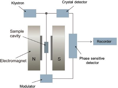
EPR spectrometers work by generating microwaves from a source (typically a klystron), sending them through an attenuator, and passing them on to the sample, which is located in a microwave cavity (Figure \(\PageIndex{1}\)). Microwaves reflected back from the cavity are routed to the detector diode, and the signal comes out as a decrease in current at the detector analogous to absorption of microwaves by the sample.
Microwave Generation
Klystrons are high power microwave vacuum tubes. They are velocity-modulated tubes that are used in radars as amplifiers or oscillators. A klystron uses the kinetic energy of an electron beam for the amplification of a high-frequency signal. Klystrons make use of the transit-time effect by varying the velocity of an electron beam. It is a linear beam device; that is, the electron flow is in a straight line focused by an axial magnetic field. The magnetic field is only used to focalize the electron beam. A klystron has one or more special cavities around the axis of the tube that modulate the electric field. Due to the number of the resonant cavities, klystrons are divided up into two-cavity klystrons, multi-cavity klystrons, and repeller klystrons.
In two-cavity klystrons there are two microwave cavity resonators, the "catcher" and the "buncher". When used as an amplifier, the weak microwave signal to be amplified is applied to the buncher cavity through a coaxial cable or waveguide, and the amplified signal is extracted from the catcher cavity.
At one end of the tube is the hot cathode which produces electrons when heated by a filament. The electrons are attracted to and pass through an anode cylinder at a high positive potential; the cathode and anode act as an electron gun to produce a high velocity stream of electrons. An external electromagnet winding creates a longitudinal magnetic field along the beam axis which prevents the beam from spreading.
The beam first passes through the "buncher" cavity resonator, through grids attached to each side. The buncher grids have an oscillating AC potential across them, produced by standing wave oscillations within the cavity, excited by the input signal at the cavity's resonant frequency applied by a coaxial cable or waveguide. The direction of the field between the grids changes twice per cycle of the input signal. Electrons entering when the entrance grid is negative and the exit grid is positive encounter an electric field in the same direction as their motion, and are accelerated by the field. Electrons entering a half-cycle later, when the polarity is opposite, encounter an electric field which opposes their motion, and are decelerated.
Microwave Waveguides
A waveguide is a structure that guides waves, such as electromagnetic waves or sound, with minimal loss of energy by restricting the transmission of energy to one direction. Without the physical constraint of a waveguide, wave intensities decrease according to the inverse square law as they expand into three dimensional space.
References
Attributions
- Klystron: https://www.radartutorial.eu/08.tran...ystron.en.html (CC BY-SA 3.0; Christian Wolff)
- Klyston: https://en.Wikipedia.org/wiki/Klystron(CC BY-SA 4.0; Wikipedia)