
1: GPIO Output (LEDs) - First Circuit
- Page ID
- 432886

\( \newcommand{\vecs}[1]{\overset { \scriptstyle \rightharpoonup} {\mathbf{#1}} } \)
\( \newcommand{\vecd}[1]{\overset{-\!-\!\rightharpoonup}{\vphantom{a}\smash {#1}}} \)
\( \newcommand{\dsum}{\displaystyle\sum\limits} \)
\( \newcommand{\dint}{\displaystyle\int\limits} \)
\( \newcommand{\dlim}{\displaystyle\lim\limits} \)
\( \newcommand{\id}{\mathrm{id}}\) \( \newcommand{\Span}{\mathrm{span}}\)
( \newcommand{\kernel}{\mathrm{null}\,}\) \( \newcommand{\range}{\mathrm{range}\,}\)
\( \newcommand{\RealPart}{\mathrm{Re}}\) \( \newcommand{\ImaginaryPart}{\mathrm{Im}}\)
\( \newcommand{\Argument}{\mathrm{Arg}}\) \( \newcommand{\norm}[1]{\| #1 \|}\)
\( \newcommand{\inner}[2]{\langle #1, #2 \rangle}\)
\( \newcommand{\Span}{\mathrm{span}}\)
\( \newcommand{\id}{\mathrm{id}}\)
\( \newcommand{\Span}{\mathrm{span}}\)
\( \newcommand{\kernel}{\mathrm{null}\,}\)
\( \newcommand{\range}{\mathrm{range}\,}\)
\( \newcommand{\RealPart}{\mathrm{Re}}\)
\( \newcommand{\ImaginaryPart}{\mathrm{Im}}\)
\( \newcommand{\Argument}{\mathrm{Arg}}\)
\( \newcommand{\norm}[1]{\| #1 \|}\)
\( \newcommand{\inner}[2]{\langle #1, #2 \rangle}\)
\( \newcommand{\Span}{\mathrm{span}}\) \( \newcommand{\AA}{\unicode[.8,0]{x212B}}\)
\( \newcommand{\vectorA}[1]{\vec{#1}} % arrow\)
\( \newcommand{\vectorAt}[1]{\vec{\text{#1}}} % arrow\)
\( \newcommand{\vectorB}[1]{\overset { \scriptstyle \rightharpoonup} {\mathbf{#1}} } \)
\( \newcommand{\vectorC}[1]{\textbf{#1}} \)
\( \newcommand{\vectorD}[1]{\overrightarrow{#1}} \)
\( \newcommand{\vectorDt}[1]{\overrightarrow{\text{#1}}} \)
\( \newcommand{\vectE}[1]{\overset{-\!-\!\rightharpoonup}{\vphantom{a}\smash{\mathbf {#1}}}} \)
\( \newcommand{\vecs}[1]{\overset { \scriptstyle \rightharpoonup} {\mathbf{#1}} } \)
\(\newcommand{\longvect}{\overrightarrow}\)
\( \newcommand{\vecd}[1]{\overset{-\!-\!\rightharpoonup}{\vphantom{a}\smash {#1}}} \)
\(\newcommand{\avec}{\mathbf a}\) \(\newcommand{\bvec}{\mathbf b}\) \(\newcommand{\cvec}{\mathbf c}\) \(\newcommand{\dvec}{\mathbf d}\) \(\newcommand{\dtil}{\widetilde{\mathbf d}}\) \(\newcommand{\evec}{\mathbf e}\) \(\newcommand{\fvec}{\mathbf f}\) \(\newcommand{\nvec}{\mathbf n}\) \(\newcommand{\pvec}{\mathbf p}\) \(\newcommand{\qvec}{\mathbf q}\) \(\newcommand{\svec}{\mathbf s}\) \(\newcommand{\tvec}{\mathbf t}\) \(\newcommand{\uvec}{\mathbf u}\) \(\newcommand{\vvec}{\mathbf v}\) \(\newcommand{\wvec}{\mathbf w}\) \(\newcommand{\xvec}{\mathbf x}\) \(\newcommand{\yvec}{\mathbf y}\) \(\newcommand{\zvec}{\mathbf z}\) \(\newcommand{\rvec}{\mathbf r}\) \(\newcommand{\mvec}{\mathbf m}\) \(\newcommand{\zerovec}{\mathbf 0}\) \(\newcommand{\onevec}{\mathbf 1}\) \(\newcommand{\real}{\mathbb R}\) \(\newcommand{\twovec}[2]{\left[\begin{array}{r}#1 \\ #2 \end{array}\right]}\) \(\newcommand{\ctwovec}[2]{\left[\begin{array}{c}#1 \\ #2 \end{array}\right]}\) \(\newcommand{\threevec}[3]{\left[\begin{array}{r}#1 \\ #2 \\ #3 \end{array}\right]}\) \(\newcommand{\cthreevec}[3]{\left[\begin{array}{c}#1 \\ #2 \\ #3 \end{array}\right]}\) \(\newcommand{\fourvec}[4]{\left[\begin{array}{r}#1 \\ #2 \\ #3 \\ #4 \end{array}\right]}\) \(\newcommand{\cfourvec}[4]{\left[\begin{array}{c}#1 \\ #2 \\ #3 \\ #4 \end{array}\right]}\) \(\newcommand{\fivevec}[5]{\left[\begin{array}{r}#1 \\ #2 \\ #3 \\ #4 \\ #5 \\ \end{array}\right]}\) \(\newcommand{\cfivevec}[5]{\left[\begin{array}{c}#1 \\ #2 \\ #3 \\ #4 \\ #5 \\ \end{array}\right]}\) \(\newcommand{\mattwo}[4]{\left[\begin{array}{rr}#1 \amp #2 \\ #3 \amp #4 \\ \end{array}\right]}\) \(\newcommand{\laspan}[1]{\text{Span}\{#1\}}\) \(\newcommand{\bcal}{\cal B}\) \(\newcommand{\ccal}{\cal C}\) \(\newcommand{\scal}{\cal S}\) \(\newcommand{\wcal}{\cal W}\) \(\newcommand{\ecal}{\cal E}\) \(\newcommand{\coords}[2]{\left\{#1\right\}_{#2}}\) \(\newcommand{\gray}[1]{\color{gray}{#1}}\) \(\newcommand{\lgray}[1]{\color{lightgray}{#1}}\) \(\newcommand{\rank}{\operatorname{rank}}\) \(\newcommand{\row}{\text{Row}}\) \(\newcommand{\col}{\text{Col}}\) \(\renewcommand{\row}{\text{Row}}\) \(\newcommand{\nul}{\text{Nul}}\) \(\newcommand{\var}{\text{Var}}\) \(\newcommand{\corr}{\text{corr}}\) \(\newcommand{\len}[1]{\left|#1\right|}\) \(\newcommand{\bbar}{\overline{\bvec}}\) \(\newcommand{\bhat}{\widehat{\bvec}}\) \(\newcommand{\bperp}{\bvec^\perp}\) \(\newcommand{\xhat}{\widehat{\xvec}}\) \(\newcommand{\vhat}{\widehat{\vvec}}\) \(\newcommand{\uhat}{\widehat{\uvec}}\) \(\newcommand{\what}{\widehat{\wvec}}\) \(\newcommand{\Sighat}{\widehat{\Sigma}}\) \(\newcommand{\lt}{<}\) \(\newcommand{\gt}{>}\) \(\newcommand{\amp}{&}\) \(\definecolor{fillinmathshade}{gray}{0.9}\)Learning Objectives
Students will be able to:
Content:
- Access the GPIO on the Raspberry Pi
- Build simple circuits
- turn an LED on and off with GPIOzero
Process:
- write code that turns on LED lights
Prior Knowledge
- Python and IoT concepts from previous activities
Further Reading
GPIO Pins
General Purpose Input/Output on the Raspberry Pi:
Know what you are doing before you connect any leads to a pin. If you directly connect a hot (3.3V or 5V) to a ground you could destroy your board. If you have doubt, look it up on the web. Always turn off the Pi when working on circuit boards
Your raspberry pi has a set of bi-directional input/output pins that allow you to interact with the physical world. There are two ways to address the numbers: Broadcom (BCM) pin numbering and board numbering. Board numbering goes from 1-40 corresponding to the pins on the device. Any pin marked GPIO can be used for input and output. Some pins are reserved as power outputs, electrical grounds, or for other purposes.
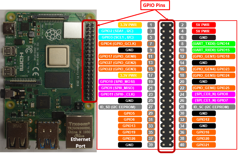 Figure \(\PageIndex{1}\): Raspberry Pi 4 with pin assignments. (Pi Belford, GPIO Diagram FreeSVG CC 0.0)
Pins
The board pins are in grey with the one position farthest away from the ethernet/USB 2.0/3.0 ports. We will be using the GPIO zero module and it is easiest to assign a pin by its GPIO number, which is not its board position number
- 8 Ground Pins (GND pins)
- If you have multiple circuits make the ground common.
- If you add new device like a sensor, make its ground common
- 4 Power Pins
- 2 3.3V pins
- 2 5V pins
- Used to power small devices like sensors
- You may need to add an external power supply.
- Never connect power pins to ground pin
- Reserved Pins
- 27,28 - used for HATs (Hardware attached on top)
- 12 GPIO Pins
- General Purpose Input Output
- All use 3.3 V
- Never connect a 5V source to a GPIO pin
- Have two states
- High (3.3V)
- Low (0V)
- Alternate Functions (Communication Protocols)
- UART (Universal Asynchronous Receiver-Transmitter)
- I2C (Inter-Integrated Circuit)
- SPI (Serial Peripheral Interface)
Critical Thinking Questions:
- What are the board numbers for GPIO pins that are closest to the USB ports on your Raspberry Pi?
- Provide the board pin number(s) for each of the following:
- Which board pins (numbers) provide 5V of electrical power potential?
- Which board pins provide 3V of electrical power potential?
- Which board pins are electrical ground?
- How many GPIO pins are available on your Raspberry Pi?
- What colors are used to represent
- Ground
- 5V
- 3V
- Input/output
- You have connected a device to board number 11. What GPIO number will you refer to for programming purposes?
Note
Whenever connecting/disconnecting items from your Raspberry Pi, you should always power off first to protect the Pi computer
Task 1: Setting up Pi and Cobbler
Setting up your Raspberry Pi to build circuits requires us to use prototyping board called a breadboard. Connect your cobbler to the 40 pin ribbon connector. Make sure your pins are not bent, and that the cobbler starts at line 1 of the breadboard.
 Figure \(\PageIndex{2}\): Breadboard connected to GPOI pins via ribbon and cobbler. Be sure to POWER OFF before connecting devices to your Pi!
The cobbler is a pcb board that you connect the ribbon two and algins the gpio pins down the length of the breadboard.
 Figure \(\PageIndex{3}\): Close-up image of both sides of Cobbler. Left sides shows pins that are placed into breadboard and the right where the ribbon cable is attached. (Belford CC-BY)
Note the grove on the top of the cobbler on the right side of picture \(\PageIndex{3}\). The ribbon has a tab that fits into this groove and so the ribbon can only be attached one way.
 Figure \(\PageIndex{4}\): This image shows how the cobbler takes the left row og GPIO pins labled A and places them on the bottom bus bars of the breadboard, while taking the right tow and placing then on the top row of bus bars. (Copyright; author via source)
One of these two Pis is set up wrong and the pins are inverted. Which one is correct?
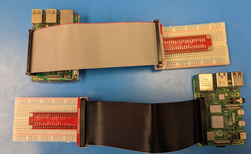 Figure \(\PageIndex{5}\): Correct and incorrect ribbon attachments. (Belford CC-BY)
- Answer
-
The bottom image is correct, and the top one has the rows switched.
If this is the first time setting up a breadboard you should watch the following video.
Companion video available here: https://youtu.be/Ljd3dpfa1JQ
The cobbler lets us connect the breadboard easily to the raspberry Pi. At this point, boot up your Raspberry Pi.
Note
There are two common types of cobblers, those with power pins (like the Vilros Cobbler) and those without power pins (like the AdaFruit Cobbler)
- Vilros Type cobbler that has 3.3V and 5V pins for the outer power rails
- Adafruit Type cobbler, which does not have these pins built into it, and so you need to run a line to the power rails
Task 2: Building your First Circuit
In this activity you will connect a red LED to a circuit on the bread board with either a 220 or 330 ohm resistor. The resistor is needed to reduce the current so you do not burn out the LED (V=IR). Before building your first circuit watch the following YouTube. Then follow the procedures below for a Vilros Cobbler (part A) or an AdaFruit cobbler (part B), depending on which type of cobbler you have. Never connect a lead across an LED without a resistor. It does not matter what side of the LED the resistor is on, as long as it is in series with the LED.
Companion video available here: https://youtu.be/R-u0DTWCcXk
Your diagram should look like that in figure \(\PageIndex{2}\)
 Figure \(\PageIndex{6}\): Basic closed loop circuit for LED. Red lines show the path of the current (Belford CC-BY)
A. Vilros Type Cobler
- Start by placing one end of a black male-to-male jumper cable in the negative (ground) line connected to 3v3 of your vilros cobbler. Connect other end of the jumpber to slot 30a.
- Slightly bend a 330 ohm resistor to make a U shape. Put one end in the 30b slot, and the other end in the 34b slot.
- Take a red LED and connect the short end (cathode) to slot 34c. Connect the long end (anode) to slot 36c.
- Place one end of a red male-to-male jumper cable in slot 36a.
- Place the other end of the red jumper cable in the 3v3 + line.
 Figure \(\PageIndex{7}\): Vilros type cobbler with power pins
B. AdaFruit Type Cobbler
- Start by placing one end of black male-to-male jumper cable in the negative (ground) line and connect it to a GND on the Adafruit Cobbler.
- Place one end of a red male-to-male jumper cable to the positive (+) line and connect it to 3V3 (Pin1) on the cobbler.
- Place one end of a black male-to-male jumper cable in the negative (ground) line connected to 3v3 of your cobbler. Connect other end of the jumper to slot 30a.
- Slightly bend a 330 ohm resistor to make a U shape. Put one end in the 30b slot, and the other end in the 34b slot.
- Take a red LED and connect the short end (cathod to slot 34c. Connect the long end (anode) to slot 36c.
- Place one end of a red male-to-male jumper cable in slot 36a.
- Place the other end of the red jumper cable in the 3v3+ line.

Note
For all subsequent builds with the Adafruit type cobbler you will need to hook up the power lines as in step 1 & 2. For the rest of the activities in this lesson you need to keep the cables to the 3.3 V pin connected, although in some subsequent activities you will be running power through the 5 V pin.
Important! If you don’t have a resistor in this circuit, you will send too much electricity to the LED. It will light up once briefly, and then not work again (much like a blown fuse or light bulb)!
Once you have built your circuit answer the following Critical Thinking Questions.
Task 3: GPIOZero Programs
Note
Included in the Raspbian OS is a library for interfacing to many simple input and output components called GPIOzero. It also has functions for more complex items such as sensors.
Remember: To stop any program from running you can use <Ctrl +C> to stop it.
We are now going to run the Raspberry Pi from a GPIO port. The code for this activity comes from the GPIO zero documentation (https://gpiozero.readthedocs.io/en/stable/). As GPIO stands for General Purpose Input Output, a GPIO pin on an electric circuit can function as in output (hot) or input (ground) pin. Use should never hook a GPIO pin to a hot source without a load and you should only run 3.3 V circuits through GPIO pins. In the following Fritzing we are using the GPIO as an output pin, and running the current from the pin through
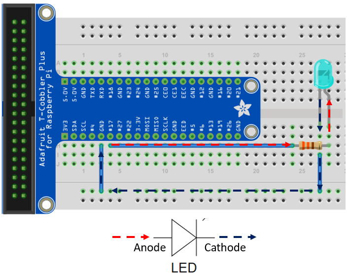 Figure \(\PageIndex{9}\): CGPIO pin 17 being run as an output. Always run a resister in series with an LED (Belford CC-BY)
After removing the hot line from the 3.3V pin and attaching it to the gpio17 pin, you whould run the following code, which comes from the gpiozero readthedocs.
gpiozero.led
| IoCT Program 3.1 |
|---|
|
Critical Thinking Questions:
- Change the value of each sleep line to 3. Rerun the program.
- Next to each line of code above, indicate what the statement does.
- Change your code to make a program that cycles your red light on and off 5 times.
Task 4: Add second LED Circuit
Connect a new yellow LED and resistor to create a new circuit connected to GPIO18.
Critical Thinking Questions:
- Alter your program to indicate a yellow LED is now on GPIO18, and it should blink in unison with the red light.
- Alter your program to have the yellow and red alternatively blink. That is when the red light is on, the yellow light is off.
gpiozero.pwmled
PWM stands for Pulse Width Modulation and the default frequency for this method is 100 Hz (see gpiozero.readthedocs.io) and the duty cycle is the fraction of time the signal is high. Because the frequency is faster than the eye can see (30 to 60 Hz, what we see is a reduction of intensity of the light proportional to the time it is off. The duty cycle is the fraction of time the signal is high.
 Figure \(\PageIndex{10}\): Various duty cycles for PWM. The default gpiozero.pwmled frequency is 100 Hz. The human eye can see 30 to 60 frames per second, so we do not see the square wavefunction, but a decrease in the light intensity. (Belford CC 0.0)
Enter the following program and run it.
| IoCT Program 3.2 |
|---|
|
Critical Thinking Questions:
- Change the led.value to other numbers between 0 and 1 and rerun the code.
- What does the PWMLED function do?
Got to READTHEDOCS and play:
https://gpiozero.readthedocs.io/en/stable/api_output.html#
Task 6: Common Anode RGB Circuit
RGB Colors
RGB stands for Red, Green and Blue, and various colors can be derived by mixing various intensities of red, green and blue. There are a variety of ways of describing these and for 8 bit coding there are values from 0 to 255 for each color, although some programs do these as fractions of 1, and so they are represented in decimals ranging from 0 to 1. The following is an RGB calculator from W3schools screen capture with values of rgb(255,255,0) that results in yellow.
 Figure \(\PageIndex{11}\):Screenshot of w3schools RGB Calculator. Note, yellow is a mixture of equal values for red and green. (Belford, cc 0.0))
Note, there are two types of RGB LEDs, common cathode and common Anode. the common is the long lead and in the common anode you hook the common to the high potential and in the common cathode you hook the common to the ground. If you look at the LED from the side where the long lead is second from the left, they run Red, Long Lead, Green and Blue. Be sure to hook up resisters and you probably want to start with the same resister value for each LED and see if the light is white. If it is not, play with the RGB picker such that you get the color you see, and then adjust the resistances in a manner that converts the color to white. Now that you have calibrate the RGB LED, you can pick a color by using the appropriate RGB values in your code.
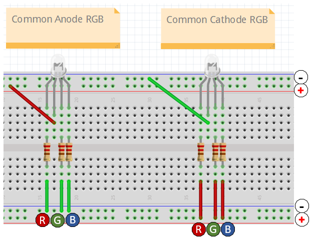 Figure \(\PageIndex{12}\): Common anode RGB LED connected with either a 220 or 330 ohm resistor.
Is the following RGB LED a common anode or cathode RGB LED? How could its wiring be improved?
 Figure \(\PageIndex{13}\): (Belford cc 0.0)
- Answer
-
Common anode as the hot is wired to the common. There is one resistor to the anode, which will work, but if you set up a single resistor to each R,G & B lead, you could tweak the resistances so the color would be better controlled. That is, the internal efficiency of each LED could vary, and as set up, they are all getting the same voltage drop.
Note, the Fritzing in exercise \(\PageIndex{1}\) has a resistor on the common and the intensity of light may be different for each color so that it will not be white when you set all RGB values in your code equal (some of the LEDs may be more efficient than others). This can be corrected by setting it up as in figure \(\PageIndex{11}\) such where you choose resistors for each line that result in white light when they all have the same RGB values in the code.
 Figure \(\PageIndex{14}\): By placing different resisters on each of the RGB lines we can set it up so the light intensity for each is the same when the values are the same. (Belford CC-BY)
Build the Following Circuit, Remember, whenever connecting/disconnecting items from your Raspberry Pi, you should always power off first, to protect the Raspberry Pi.
Note
RGB (Red Green Blue) is an additive color model based on 8 bits, see, https://rgbcolorcode.com/. (R,G,B) values of (0,0,0) corresponds to black and (255,255,255) corresponds to white. It is not important that you use slots 44-47, but the 4 pins on the common anode RGB LED are short/long/short/short, and in that order represent R/Anode/G/B. You then need to connect the Anode to hot, and the R,G & B to the gpio pins as defined in your code. The first line of code in IOCT Program 3.3 states: led=REBLED(red=6, green=13, blue=19), and so we are connecting the red to gpio6, green to gpio 13 and blue to gpio19. You can use any GPIO pin you want, as long as you properly assign it in your code.
Enter the following program and run it.
| IOCT Program 3.3 |
|---|
|
Critical Thinking Questions
- Next to each line of code above, indicate what that does.
- How does changing the values affect the program?
Enter the following program and run it, realize you need to use the GPIO pins you are using on your breadboard.
| IoCT Program 3.4 |
|---|
|
Critical Thinking Questions:
- Next to each led.color line in the code above, write the color the LED makes.
- Color mixed light in equal amounts of red and green should give a yellow light. Color mixed in equal amounts of red and blue should give a magenta/purple light. Alter the code above to have values in line 12 to have equal amounts of red and blue, and line 14 be equal amounts of red and green. Why did the original code not use equal values?
- Color mixed light in equal amounts of red, green, and blue should give a white light. Write a new program that will make the LED produce white light. Report your values to the class.
Now Go to Readthedocs.io and play with RGBLED class of GPIO zero
https://gpiozero.readthedocs.io/en/stable/api_output.html#rgbled
Acknowledgements
The material in this lesson plan was originally developed by Ehren Bucholtz of the University of Health Sciences and Pharmacy in Saint Louis.