10.3: UV/Vis and IR Spectroscopy
( \newcommand{\kernel}{\mathrm{null}\,}\)
In Figure 10.9 we examined Nessler’s original method for matching the color of a sample to the color of a standard. Matching the colors was a labor intensive process for the analyst. Not surprisingly, spectroscopic methods of analysis were slow to develop. The 1930s and 1940s saw the introduction of photoelectric transducers for ultraviolet and visible radiation, and thermocouples for infrared radiation. As a result, modern instrumentation for absorption spectroscopy became routinely available in the 1940s—progress has been rapid ever since.
10.3.1 Instrumentation
Frequently an analyst must select—from among several instruments of different design—the one instrument best suited for a particular analysis. In this section we examine several different instruments for molecular absorption spectroscopy, emphasizing their advantages and limitations. Methods of sample introduction are also covered in this section.
Instrument Designs for Molecular UV/Vis Absorption
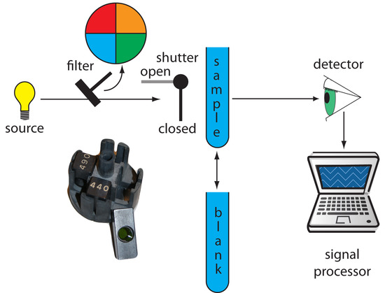
Filter Photometer. The simplest instrument for molecular UV/Vis absorption is a filter photometer (Figure 10.25), which uses an absorption or interference filter to isolate a band of radiation. The filter is placed between the source and the sample to prevent the sample from decomposing when exposed to higher energy radiation. A filter photometer has a single optical path between the source and detector, and is called a single-beam instrument. The instrument is calibrated to 0% T while using a shutter to block the source radiation from the detector. After opening the shutter, the instrument is calibrated to 100% T using an appropriate blank. The blank is then replaced with the sample and its transmittance measured. Because the source’s incident power and the sensitivity of the detector vary with wavelength, the photometer must be recalibrated whenever the filter is changed. Photometers have the advantage of being relatively inexpensive, rugged, and easy to maintain. Another advantage of a photometer is its portability, making it easy to take into the field. Disadvantages of a photometer include the inability to record an absorption spectrum and the source’s relatively large effective bandwidth, which limits the calibration curve’s linearity.
Note
The percent transmittance varies between 0% and 100%. As we learned in Figure 10.21, we use a blank to determine P0, which corresponds to 100% T. Even in the absence of light the detector records a signal. Closing the shutter allows us to assign 0% T to this signal. Together, setting 0% T and 100% T calibrates the instrument. The amount of light passing through a sample produces a signal that is greater than or equal to that for 0% T and smaller than or equal to that for 100%T.
Figure 10.25 Schematic diagram of a filter photometer. The analyst either inserts a removable filter or the filters are placed in a carousel, an example of which is shown in the photographic inset. The analyst selects a filter by rotating it into place.
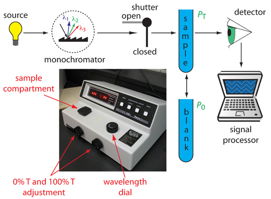
Single-Beam Spectrophotometer. An instrument that uses a monochromator for wavelength selection is called a spectrophotometer. The simplest spectrophotometer is a single-beam instrument equipped with a fixed-wavelength monochromator (Figure 10.26). Single-beam spectrophotometers are calibrated and used in the same manner as a photometer. One example of a single-beam spectrophotometer is Thermo Scientific’s Spectronic 20D+, which is shown in the photographic insert to Figure 10.26. The Spectronic 20D+ has a range of 340–625 nm (950 nm when using a red-sensitive detector), and a fixed effective bandwidth of 20 nm. Battery-operated, hand-held single-beam spectrophotometers are available, which are easy to transport into the field. Other single-beam spectrophotometers also are available with effective bandwidths of 2–8 nm. Fixed wavelength single-beam spectrophotometers are not practical for recording spectra because manually adjusting the wavelength and recalibrating the spectrophotometer is awkward and time-consuming. The accuracy of a single-beam spectrophotometer is limited by the stability of its source and detector over time.
Figure 10.26 Schematic diagram of a fixed-wavelength single-beam spectrophotometer. The photographic inset shows a typical instrument. The shutter remains closed until the sample or blank is placed in the sample compartment. The analyst manually selects the wavelength by adjusting the wavelength dial. Inset photo modified from: Adi (www.commons.wikipedia.org).
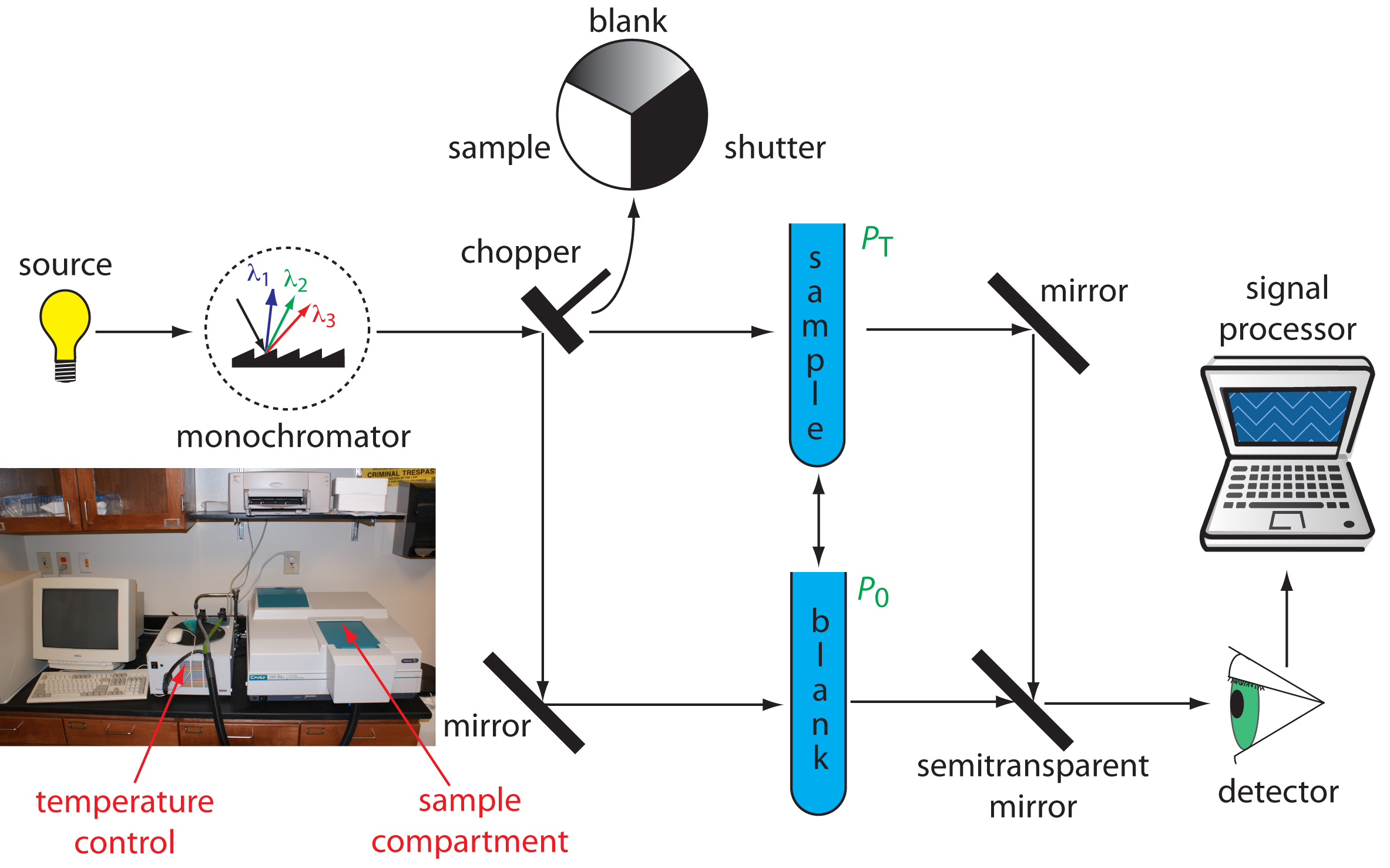
Double-Beam Spectrophotometer. The limitations of fixed-wavelength, single-beam spectrophotometers are minimized by using a double-beam spectrophotometer (Figure 10.27). A chopper controls the radiation’s path, alternating it between the sample, the blank, and a shutter. The signal processor uses the chopper’s known speed of rotation to resolve the signal reaching the detector into the transmission of the blank, P0, and the sample, PT. By including an opaque surface as a shutter, it is possible to continuously adjust 0% T. The effective bandwidth of a double-beam spectrophotometer is controlled by adjusting the monochromator’s entrance and exit slits. Effective bandwidths of 0.2–3.0 nm are common. A scanning monochromator allows for the automated recording of spectra. Double-beam instruments are more versatile than single-beam instruments, being useful for both quantitative and qualitative analyses, but also are more expensive.
Figure 10.27 Schematic diagram of a scanning, double-beam spectrophotometer. A chopper directs the source’s radiation, using a transparent window to pass radiation to the sample and a mirror to reflect radiation to the blank. The chopper’s opaque surface serves as a shutter, which allows for a constant adjustment of the spectrophotometer’s 0% T. The photographic insert shows a typical instrument. The unit in the middle of the photo is a temperature control unit that allows the sample to be heated or cooled.
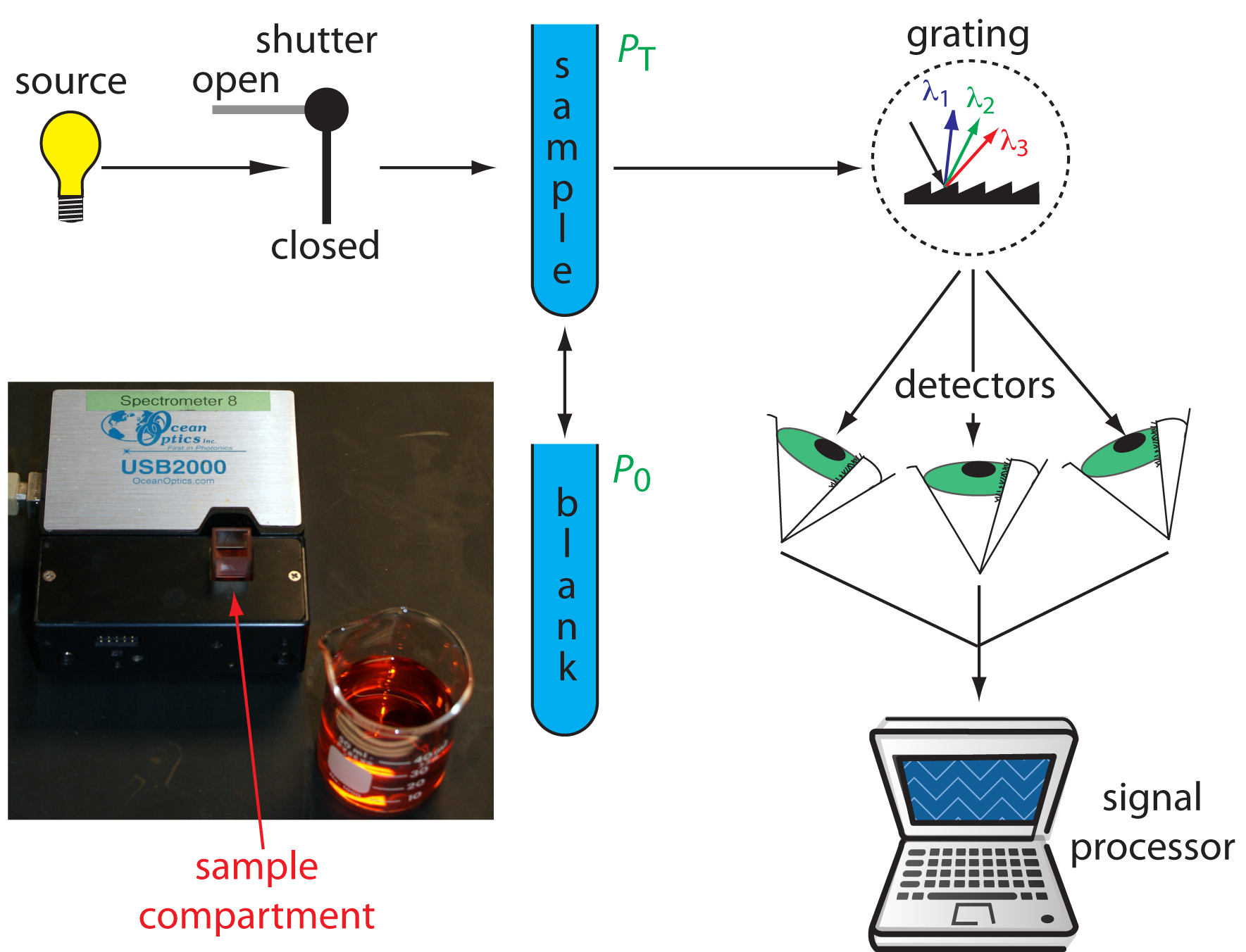
Diode Array Spectrometer. An instrument with a single detector can monitor only one wavelength at a time. If we replace a single photomultiplier with many photodiodes, we can use the resulting array of detectors to record an entire spectrum simultaneously in as little as 0.1 s. In a diode array spectrometer the source radiation passes through the sample and is dispersed by a grating (Figure 10.28). The photodiode array is situated at the grating’s focal plane, with each diode recording the radiant power over a narrow range of wavelengths. Because we replace a full monochromator with just a grating, a diode array spectrometer is small and compact.
Figure 10.28 Schematic diagram of a diode array spectrophotometer. The photographic insert shows a typical instrument. Note that the 50-mL beaker provides a sense of scale.
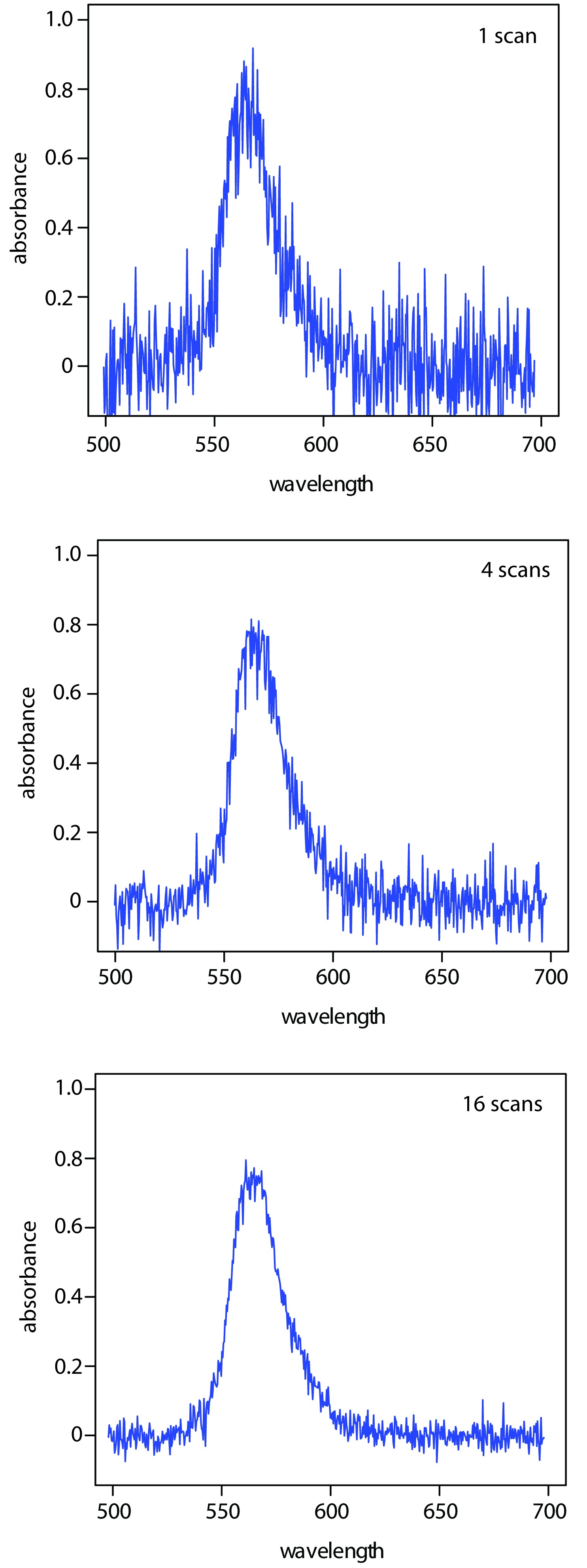
One advantage of a diode array spectrometer is the speed of data acquisition, which allows to collect several spectra for a single sample. Individual spectra are added and averaged to obtain the final spectrum. This signal averaging improves a spectrum’s signal-to-noise ratio. If we add together n spectra, the sum of the signal at any point, x, increases as nSx, where Sx is the signal. The noise at any point, Nx, is a random event, which increases as √nNx when we add together n spectra. The signal-to-noise ratio (S/N) after n scans is
SN=nSx√nNx=√nSxnNx
where Sx/Nx is the signal-to-noise ratio for a single scan. The impact of signal averaging is shown in Figure 10.29. The first spectrum shows the signal for a single scan, which consists of a single, noisy peak. Signal averaging using 4 scans and 16 scans decreases the noise and improves the signal-to-noise ratio. One disadvantage of a photodiode array is that the effective bandwidth per diode is roughly an order of magnitude larger than that for a high quality monochromator.
Figure 10.29 Effect of signal averaging on a spectrum’s signal-to-noise ratio. From top to bottom: spectrum for a single scan; average spectrum after four scans; and average spectrum after adding 16 scans.
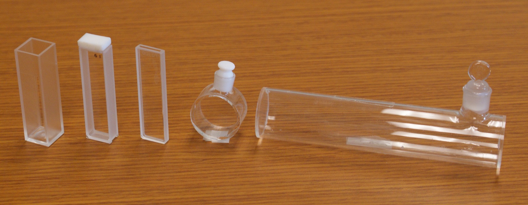
Sample Cells. The sample compartment provides a light-tight environment that limits the addition of stray radiation. Samples are normally in the liquid or solution state, and are placed in cells constructed with UV/Vis transparent materials, such as quartz, glass, and plastic (Figure 10.30). A quartz or fused-silica cell is required when working at a wavelength <300 nm where other materials show a significant absorption. The most common pathlength is 1 cm (10 mm), although cells with shorter (as little as 0.1 cm) and longer pathlengths (up to 10 cm) are available. Longer pathlength cells are useful when analyzing a very dilute solution, or for gas samples. The highest quality cells allow the radiation to strike a flat surface at a 90o angle, minimizing the loss of radiation to reflection. A test tube is often used as a sample cell with simple, single-beam instruments, although differences in the cell’s pathlength and optical properties add an additional source of error to the analysis.
Figure 10.30 Examples of sample cells for UV/Vis spectroscopy. From left to right (with path lengths in parentheses): rectangular plastic cuvette (10.0 mm), rectangular quartz cuvette (5.000 mm), rectangular quartz cuvette (1.000 mm), cylindrical quartz cuvette (10.00 mm), cylindrical quartz cuvette (100.0 mm). Cells often are available as a matched pair, which is important when using a double-beam instrument.
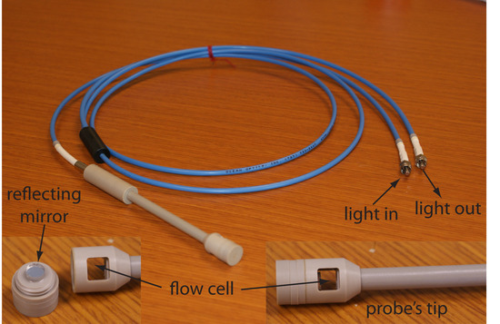
If we need to monitor an analyte’s concentration over time, it may not be possible to physically remove samples for analysis. This is often the case, for example, when monitoring industrial production lines or waste lines, when monitoring a patient’s blood, or when monitoring environmental systems. With a fiber-optic probe we can analyze samples in situ. An example of a remote sensing fiber-optic probe is shown in Figure 10.31. The probe consists of two bundles of fiber-optic cable. One bundle transmits radiation from the source to the probe’s tip, which is designed to allow the sample to flow through the sample cell. Radiation from the source passes through the solution and is reflected back by a mirror. The second bundle of fiber-optic cable transmits the nonabsorbed radiation to the wavelength selector. Another design replaces the flow cell shown in Figure 10.31 with a membrane containing a reagent that reacts with the analyte. When the analyte diffuses across the membrane it reacts with the reagent, producing a product that absorbs UV or visible radiation. The nonabsorbed radiation from the source is reflected or scattered back to the detector. Fiber optic probes that show chemical selectivity are called optrodes.6
Figure 10.31 Example of a fiber-optic probe. The inset photographs provide a close-up look at the probe’s flow cell and the reflecting mirror.
Instrument Designs for Infrared Absorption
Filter Photometer. The simplest instrument for IR absorption spectroscopy is a filter photometer similar to that shown in Figure 10.25 for UV/Vis absorption. These instruments have the advantage of portability, and typically are used as dedicated analyzers for gases such as HCN and CO.
Double-beam spectrophotometer. Infrared instruments using a monochromator for wavelength selection use double-beam optics similar to that shown in Figure 10.27. Double-beam optics are preferred over single-beam optics because the sources and detectors for infrared radiation are less stable than those for UV/Vis radiation. In addition, it is easier to correct for the absorption of infrared radiation by atmospheric CO2 and H2O vapor when using double-beam optics. Resolutions of 1–3 cm–1 are typical for most instruments.
Fourier transform spectrometer. In a Fourier transform infrared spectrometer, or FT–IR, the monochromator is replaced with an interferometer (Figure 10.13). Because an FT-IR includes only a single optical path, it is necessary to collect a separate spectrum to compensate for the absorbance of atmospheric CO2 and H2O vapor. This is done by collecting a background spectrum without the sample and storing the result in the instrument’s computer memory. The background spectrum is removed from the sample’s spectrum by ratioing the two signals. In comparison to other instrument designs, an FT–IR provides for rapid data acquisition, allowing an enhancement in signal-to-noise ratio through signal-averaging.
Sample Cells. Infrared spectroscopy is routinely used to analyze gas, liquid, and solid samples. Sample cells are made from materials, such as NaCl and KBr, that are transparent to infrared radiation. Gases are analyzed using a cell with a pathlength of approximately 10 cm. Longer pathlengths are obtained by using mirrors to pass the beam of radiation through the sample several times.
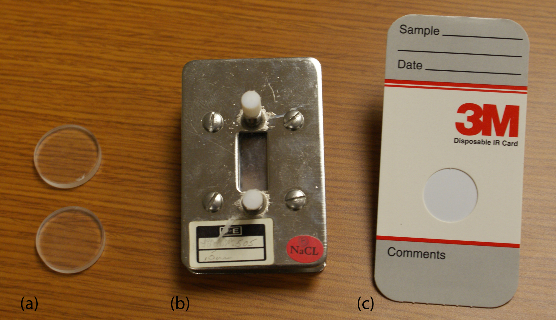
A liquid samples may be analyzed using a variety of different sample cells (Figure 10.32). For non-volatile liquids a suitable sample can be prepared by placing a drop of the liquid between two NaCl plates, forming a thin film that typically is less than 0.01 mm thick. Volatile liquids must be placed in a sealed cell to prevent their evaporation.
Figure 10.32 Three examples of IR sample cells: (a) NaCl salts plates; (b) fixed pathlength (0.5 mm) sample cell with NaCl windows; (c) disposable card with a polyethylene window that is IR transparent with the exception of strong absorption bands at 2918 cm–1 and 2849 cm–1.
The analysis of solution samples is limited by the solvent’s IR absorbing properties, with CCl4, CS2, and CHCl3 being the most common solvents. Solutions are placed in cells containing two NaCl windows separated by a Teflon spacer. By changing the Teflon spacer, pathlengths from 0.015–1.0 mm can be obtained.
Transparent solid samples can be analyzed directly by placing them in the IR beam. Most solid samples, however, are opaque, and must be dispersed in a more transparent medium before recording the IR spectrum. If a suitable solvent is available, then the solid can be analyzed by preparing a solution and analyzing as described above. When a suitable solvent is not available, solid samples may be analyzed by preparing a mull of the finely powdered sample with a suitable oil. Alternatively, the powdered sample can be mixed with KBr and pressed into an optically transparent pellet.
The analysis of an aqueous sample is complicated by the solubility of the NaCl cell window in water. One approach to obtaining infrared spectra on aqueous solutions is to use attenuated total reflectance instead of transmission. Figure 10.33 shows a diagram of a typical attenuated total reflectance (ATR) FT–IR instrument. The ATR cell consists of a high refractive index material, such as ZnSe or diamond, sandwiched between a low refractive index substrate and a lower refractive index sample. Radiation from the source enters the ATR crystal where it undergoes a series of total internal reflections before exiting the crystal. During each reflection the radiation penetrates into the sample to a depth of a few microns. The result is a selective attenuation of the radiation at those wavelengths where the sample absorbs. ATR spectra are similar, but not identical, to those obtained by measuring the transmission of radiation.
Figure 10.33 FT-IR spectrometer equipped with a diamond ATR sample cell. The inserts show a close-up photo of the sample platform, a sketch of the ATR’s sample slot, and a schematic showing how the source’s radiation interacts with the sample. The pressure tower is used to ensure the contact of solid samples with the ATR crystal.
Solid samples also can be analyzed using an ATR sample cell. After placing the solid in the sample slot, a compression tip ensures that it is in contact with the ATR crystal. Examples of solids that have been analyzed by ATR include polymers, fibers, fabrics, powders, and biological tissue samples. Another reflectance method is diffuse reflectance, in which radiation is reflected from a rough surface, such as a powder. Powdered samples are mixed with a non-absorbing material, such as powdered KBr, and the reflected light is collected and analyzed. As with ATR, the resulting spectrum is similar to that obtained by conventional transmission methods.
Note
Further details about these, and other methods for preparing solids for infrared analysis can be found in this chapter’s additional resources.
10.3.2 Quantitative Applications
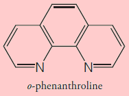
The determination of an analyte’s concentration based on its absorption of ultraviolet or visible radiation is one of the most frequently encountered quantitative analytical methods. One reason for its popularity is that many organic and inorganic compounds have strong absorption bands in the UV/Vis region of the electromagnetic spectrum. In addition, if an analyte does not absorb UV/Vis radiation—or if its absorbance is too weak—we often can react it with another species that is strongly absorbing. For example, a dilute solution of Fe2+ does not absorb visible light. Reacting Fe2+ with o-phenanthroline, however, forms an orange–red complex of Fe(phen)32+ that has a strong, broad absorbance band near 500 nm. An additional advantage to UV/Vis absorption is that in most cases it is relatively easy to adjust experimental and instrumental conditions so that Beer’s law is obeyed.
Note
Figure 10.18 shows the visible spectrum for Fe(phen)32+.
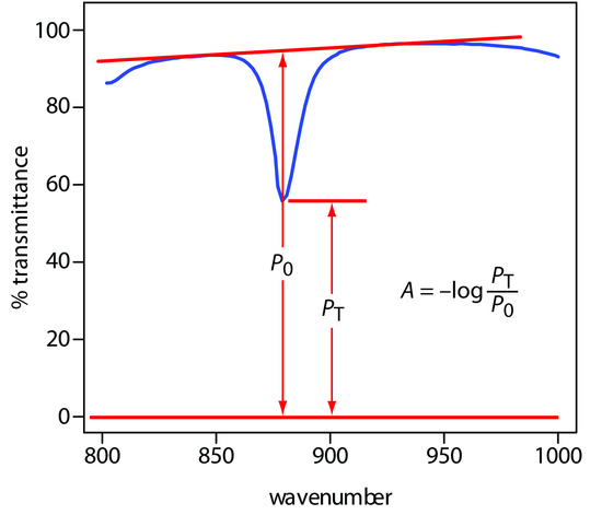
A quantitative analysis based on the absorption of infrared radiation, although important, is less frequently encountered than those for UV/Vis absorption. One reason is the greater tendency for instrumental deviations from Beer’s law when using infrared radiation. Because an infrared absorption band is relatively narrow, any deviation due to the lack of monochromatic radiation is more pronounced. In addition, infrared sources are less intense than UV/Vis sources, making stray radiation more of a problem. Differences in pathlength for samples and standards when using thin liquid films or KBr pellets are a problem, although an internal standard can be used to correct for any difference in pathlength. Finally, establishing a 100% T (A = 0) baseline is often difficult because the optical properties of NaCl sample cells may change significantly with wavelength due to contamination and degradation. We can minimize this problem by measuring absorbance relative to a baseline established for the absorption band. Figure 10.34 shows how this is accomplished.
Note
Another approach is to use a cell with a fixed pathlength, such as that shown in Figure 10.32b.
Figure 10.34 Method for determining absorbance from an IR spectrum.
Environmental Applications
The analysis of waters and wastewaters often relies on the absorption of ultraviolet and visible radiation. Many of these methods are outlined in Table 10.6. Several of these methods are described here in more detail.
|
Analyte |
Method |
λ (nm) |
|---|---|---|
|
Trace Metals |
||
|
aluminum |
react with Eriochrome cyanide R dye at pH6; forms red to pink complex |
535 |
|
arsenic |
reduce to AsH3 using Zn and react with silver diethyldithiocarbamate; forms red complex |
535 |
|
cadmium |
extract into CHCl3 containing dithizone from a sample made basic with NaOH; forms pink to red complex |
518 |
|
chromium |
oxidize to Cr(VI) and react with diphenylcarbazide; forms red-violet product |
540 |
|
copper |
react with neocuprine in neutral to slightly acid solution and extract into CHCl3/CH3OH; forms yellow complex |
457 |
|
iron |
reduce to Fe2+ and react with o-phenanthroline; forms orange-red complex |
510 |
|
lead |
extract into CHCl3 containing dithizone from sample made basic with NH3/NH4+ buffer; forms cherry red complex |
510 |
|
manganese |
oxidize to MnO4– with persulfate; forms purple solution |
525 |
|
mercury |
extract into CHCl3 containing dithizone from acidic sample; forms orange complex |
492 |
|
zinc |
react with zincon at pH 9; forms blue complex |
620 |
|
Inorganic Nonmetals |
||
|
ammonia |
reaction with hypochlorite and phenol using a manganous salt catalyst; forms blue indophenol as product |
630 |
|
cyanide |
react with chloroamine-T to form CNCl and then with a pyridine-barbituric acid; forms a red-blue dye |
578 |
|
fluoride |
react with red Zr-SPADNS lake; formation of ZrF62– decreases color of the red lake |
570 |
|
chlorine (residual) |
react with leuco crystal violet; forms blue product |
592 |
|
nitrate |
react with Cd to form NO2– and then react with sulfanilamide and N-(1-napthyl)-ethylenediamine; forms red azo dye |
543 |
|
phosphate |
react with ammonium molybdate and then reduce with SnCl2; forms molybdenum blue |
690 |
|
Organics |
||
|
phenol |
react with 4-aminoantipyrine and K3Fe(CN)6; forms yellow antipyrine dye |
460 |
|
anionic surfactant |
react with cationic methylene blue dye and extract into CHCl3; forms blue ion pair |
652 |
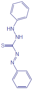 Although the quantitative analysis of metals in waters and wastewaters is accomplished primarily by atomic absorption or atomic emission spectroscopy, many metals also can be analyzed following the formation of a colored metal–ligand complex. One advantage to these spectroscopic methods is that they are easily adapted to the analysis of samples in the field using a filter photometer. One ligand that is used in the analysis of several metals is diphenylthiocarbazone, also known as dithizone. Dithizone is not soluble in water, but when a solution of dithizone in CHCl3 is shaken with an aqueous solution containing an appropriate metal ion, a colored metal–dithizonate complex forms that is soluble in CHCl3. The selectivity of dithizone is controlled by adjusting the sample’s pH. For example, Cd2+ is extracted from solutions that are made strongly basic with NaOH, Pb2+ from solutions that are made basic with an NH3/NH4+ buffer, and Hg2+ from solutions that are slightly acidic.
Note
Atomic absorption is the subject of Section 10.4 and atomic emission is the subject of Section 10.7.
The structure of dithizone is shown to the right. See Chapter 7 for a discussion of extracting metal ions using dithizone.
When chlorine is added to water the portion available for disinfection is called the chlorine residual. There are two forms of chlorine residual. The free chlorine residual includes Cl2, HOCl, and OCl–. The combined chlorine residual, which forms from the reaction of NH3 with HOCl, consists of monochloramine, NH2Cl, dichloramine, NHCl2, and trichloramine, NCl3. Because the free chlorine residual is more efficient at disinfection, there is an interest in methods that can distinguish between the different forms of the total chlorine residual. One such method is the leuco crystal violet method. The free residual chlorine is determined by adding leuco crystal violet to the sample, which instantaneously oxidizes to give a blue colored compound that is monitored at 592 nm. Completing the analysis in less than five minutes prevents a possible interference from the combined chlorine residual. The total chlorine residual (free + combined) is determined by reacting a separate sample with iodide, which reacts with both chlorine residuals to form HOI. When the reaction is complete, leuco crystal violet is added and oxidized by HOI, giving the same blue colored product. The combined chlorine residual is determined by difference.
Note
In Chapter 9 we explored how the total chlorine residual can be determined by a redox titration; see Representative Method 9.3 for further details. The method described here allows us to divide the total chlorine residual into its component parts.
The concentration of fluoride in drinking water may be determined indirectly by its ability to form a complex with zirconium. In the presence of the dye SPADNS, solutions of zirconium form a red colored compound, called a lake, that absorbs at 570 nm. When fluoride is added, the formation of the stable ZrF62– complex causes a portion of the lake to dissociate, decreasing the absorbance. A plot of absorbance versus the concentration of fluoride, therefore, has a negative slope.
Note
SPADNS, which is shown below, is an abbreviation for the sodium salt of 2-(4-sulfophenylazo)-1,8-dihydroxy-3,6-napthalenedisulfonic acid, which is a mouthful to say.

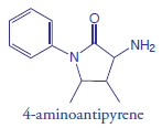 Spectroscopic methods also are used to determine organic constituents in water. For example, the combined concentrations of phenol, and ortho- and meta- substituted phenols are determined by using steam distillation to separate the phenols from nonvolatile impurities. The distillate reacts with 4-aminoantipyrine at pH 7.9 ± 0.1 in the presence of K3Fe(CN)6, forming a yellow colored antipyrine dye. After extracting the dye into CHCl3, its absorbance is monitored at 460 nm. A calibration curve is prepared using only the unsubstituted phenol, C6H5OH. Because the molar absorptivity of substituted phenols are generally less than that for phenol, the reported concentration represents the minimum concentration of phenolic compounds.
Molecular absorption also can be used for the analysis of environmentally significant airborne pollutants. In many cases the analysis is carried out by collecting the sample in water, converting the analyte to an aqueous form that can be analyzed by methods such as those described in Table 10.6. For example, the concentration of NO2 can be determined by oxidizing NO2 to NO3–. The 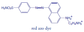 concentration of NO3– is then determined by first reducing it to NO2– with Cd, and then reacting NO2– with sulfanilamide and N-(1-naphthyl)-ethylenediamine to form a red azo dye. Another important application is the analysis for SO2, which is determined by collecting the sample in an aqueous solution of HgCl42– where it reacts to form Hg(SO3)22–. Addition of p-rosaniline and formaldehyde produces a purple complex that is monitored at 569 nm. Infrared absorption is useful for the analysis of organic vapors, including HCN, SO2, nitrobenzene, methyl mercaptan, and vinyl chloride. Frequently, these analyses are accomplished using portable, dedicated infrared photometers.
Clinical Applications
The analysis of clinical samples is often complicated by the complexity of the sample matrix, which may contribute a significant background absorption at the desired wavelength. The determination of serum barbiturates provides one example of how this problem is overcome. The barbiturates are first extracted from a sample of serum with CHCl3 and then extracted from the CHCl3 into 0.45 M NaOH (pH ≈ 13). The absorbance of the aqueous extract is measured at 260 nm, and includes contributions from the barbiturates as well as other components extracted from the serum sample. The pH of the sample is then lowered to approximately 10 by adding NH4Cl and the absorbance remeasured. Because the barbiturates do not absorb at this pH, we can use the absorbance at pH 10, ApH 10, to correct the absorbance at pH 13, ApH 13
Abarb=ApH 13−Vsamp+VNH4ClVsamp×ApH 10
where Abarb is the absorbance due to the serum barbiturates, and Vsamp and VNH4Cl are the volumes of sample and NH4Cl, respectively. Table 10.7 provides a summary of several other methods for analyzing clinical samples.
|
Analyte |
Method |
λ (nm) |
|---|---|---|
|
total serum protein |
react with NaOH and Cu2+; forms blue-violet complex |
540 |
|
serum cholesterol |
react with Fe3+ in presence of isopropanol, acetic acid, and H2SO4; forms blue-violet complex |
540 |
|
uric acid |
react with phosphotungstic acid; forms tungsten blue |
710 |
|
serum barbiturates |
extract into CHCl3 to isolate from interferents and then extract into 0.45 M NaOH |
260 |
|
glucose |
react with o-toludine at 100oC; forms blue-green complex |
630 |
|
protein-bound iodine |
decompose protein to release iodide, which catalyzes redox reaction between Ce3+ and As3+; forms yellow colored Ce4+ |
420 |
Industrial Analysis
UV/Vis molecular absorption is used for the analysis of a diverse array of industrial samples including pharmaceuticals, food, paint, glass, and metals. In many cases the methods are similar to those described in Table 10.6 and Table 10.7. For example, the amount of iron in food can be determined by bringing the iron into solution and analyzing using the o-phenanthroline method listed in Table 10.6.
Many pharmaceutical compounds contain chromophores that make them suitable for analysis by UV/Vis absorption. Products that have been analyzed in this fashion include antibiotics, hormones, vitamins, and analgesics. One example of the use of UV absorption is in determining the purity of aspirin tablets, for which the active ingredient is acetylsalicylic acid. Salicylic acid, which is produced by the hydrolysis of acetylsalicylic acid, is an undesirable impurity in aspirin tablets, and should not be present at more than 0.01% w/w. Samples can be screened for unacceptable levels of salicylic acid by monitoring the absorbance at a wavelength of 312 nm. Acetylsalicylic acid absorbs at 280 nm, but absorbs poorly at 312 nm. Conditions for preparing the sample are chosen such that an absorbance of greater than 0.02 signifies an unacceptable level of salicylic acid.
Forensic Applications
UV/Vis molecular absorption is routinely used for the analysis of narcotics and for drug testing. One interesting forensic application is the determination of blood alcohol using the Breathalyzer test. In this test a 52.5-mL breath sample is bubbled through an acidified solution of K2Cr2O7, which oxidizes ethanol to acetic acid. The concentration of ethanol in the breath sample is determined by the decrease in absorbance at 440 nm where the dichromate ion absorbs. A blood alcohol content of 0.10%, which is above the legal limit, corresponds to 0.025 mg of ethanol in the breath sample.
Developing a Quantitative Method for a Single Component
In developing a quantitative analytical method, the conditions under which Beer’s law is obeyed must be established. First, the most appropriate wavelength for the analysis is determined from an absorption spectrum. In most cases the best wavelength corresponds to an absorption maximum because it provides greater sensitivity and is less susceptible to instrumental limitations. Second, if an instrument with adjustable slits is being used, then an appropriate slit width needs to be chosen. The absorption spectrum also aids in selecting a slit width. Usually we set the slits to be as wide as possible because this increases the throughput of source radiation, while also being narrow enough to avoid instrumental limitations to Beer’s law. Finally, a calibration curve is constructed to determine the range of concentrations for which Beer’s law is valid. Additional considerations that are important in any quantitative method are the effect of potential interferents and establishing an appropriate blank.
Note
The best way to appreciate the theoretical and practical details discussed in this section is to carefully examine a typical analytical method. Although each method is unique, the following description of the determination of iron in water and wastewater provides an instructive example of a typical procedure. The description here is based on Method 3500- Fe B as published in Standard Methods for the Examination of Water and Wastewater, 20th Ed., American Public Health Association: Washington, D. C., 1998.
Determination of Iron in Water and Wastewater
Description of Method
Iron in the +2 oxidation state reacts with o-phenanthroline to form the orange-red Fe(phen)32+ complex. The intensity of the complex’s color is independent of solution acidity between a pH of 3 and 9. Because the complex forms more rapidly at lower pH levels, the reaction is usually carried out within a pH range of 3.0–3.5. Any iron present in the +3 oxidation state is reduced with hydroxylamine before adding o-phenanthroline. The most important interferents are strong oxidizing agents, polyphosphates, and metal ions such as Cu2+, Zn2+, Ni2+, and Cd2+. An interference from oxidizing agents is minimized by adding an excess of hydroxylamine, and an interference from polyphosphate is minimized by boiling the sample in the presence of acid. The absorbance of samples and standards are measured at a wavelength of 510 nm using a 1-cm cell (longer pathlength cells also may be used). Beer’s law is obeyed for concentrations of within the range of 0.2–4.0 mg Fe/L.
(Figure 10.18 shows the visible spectrum for Fe(phen)32+.)
Procedure
For samples containing less than 2 mg Fe/L, directly transfer a 50-mL portion to a 125-mL Erlenmeyer flask. Samples containing more than 2 mg Fe/L must be diluted before acquiring the 50-mL portion. Add 2 mL of concentrated HCl and 1 mL of hydroxylamine to the sample. Heat the solution to boiling and continue boiling until the solution’s volume is reduced to between 15 and 20 mL. After cooling to room temperature, transfer the solution to a 50-mL volumetric flask, add 10 mL of an ammonium acetate buffer, 2 mL of a 1000 ppm solution of o-phenanthroline, and dilute to volume. Allow 10–15 minutes for color development before measuring the absorbance, using distilled water to set 100% T. Calibration standards, including a blank, are prepared by the same procedure using a stock solution containing a known concentration of Fe2+.
Questions
1. Explain why strong oxidizing agents are interferents, and why an excess of hydroxylamine prevents the interference.
A strong oxidizing agent oxidizes some Fe2+ to Fe3+. Because Fe(phen)33+ does not absorb as strongly as Fe(phen)32+, the absorbance decreases, producing a negative determinate error. The excess hydroxylamine reacts with the oxidizing agents, removing them from the solution.
2. The color of the complex is stable between pH levels of 3 and 9. What are some possible complications at more acidic or more basic pH’s?
Because o-phenanthroline is a weak base, its conditional formation constant for Fe(phen)32+ is less favorable at more acidic pH levels, where o-phenanthroline is protonated. The result is a decrease in absorbance and a less sensitive analytical method.
(In Chapter 9 we saw the same effect of pH on the complexation reactions between EDTA and metal ions.)
When the pH is greater than 9, competition between OH– and o-phenanthroline for Fe2+ also decreased the absorbance. In addition, if the pH is sufficiently basic there is a risk that the iron will precipitate as Fe(OH)2.
3. Cadmium is an interferent because it forms a precipitate with o-phenanthroline. What effect would the formation of precipitate have on the determination of iron?
Because o-phenanthroline is present in large excess (2000 μg of o-phenanthroline for 100 μg of Fe2+), it is not likely that the interference is due to an insufficient amount of o-phenanthroline being available to react with the Fe2+. The presence of a precipitate in the sample cell results in the scattering of radiation, which causes an apparent increase in absorbance. Because the measured absorbance increases, the reported concentration is too high.
(Although scattering is a problem here, it can serve as the basis of a useful analytical method. See Section 10.8 for further details.)
4. Even high quality ammonium acetate contains a significant amount of iron. Why is this source of iron not a problem?
Because all samples and standards are prepared using the same volume of ammonium acetate buffer, the contribution of this source of iron is accounted for by the calibration curve’s reagent blank.
Quantitative Analysis for a Single Analyte
To determine the concentration of a an analyte we measure its absorbance and apply Beer’s law using any of the standardization methods described in Chapter 5. The most common methods are a normal calibration curve using external standards and the method of standard additions. A single point standardization is also possible, although we must first verify that Beer’s law holds for the concentration of analyte in the samples and the standard.
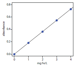
The determination of Fe in an industrial waste stream was carried out by the o‑phenanthroline described in Representative Method 10.1. Using the data in the following table, determine the mg Fe/L in the waste stream.
|
mg Fe/L |
absorbance |
|
0.00 |
0.000 |
|
1.00 |
0.183 |
|
2.00 |
0.364 |
|
3.00 |
0.546 |
|
4.00 |
0.727 |
|
sample |
0.269 |
Solution
Linear regression of absorbance versus the concentration of Fe in the standards gives a calibration curve with the following equation.
A=0.0006+0.1817×(mgFe/L)
Substituting the sample’s absorbance into the calibration expression gives the concentration of Fe in the waste stream as 1.48 mg Fe/L.
The concentration of Cu2+ in a sample can be determined by reacting it with the ligand cuprizone and measuring its absorbance at 606 nm in a 1.00-cm cell. When a 5.00-mL sample is treated with cuprizone and diluted to 10.00 mL, the resulting solution has an absorbance of 0.118. A second 5.00-mL sample is mixed with 1.00 mL of a 20.00 mg/L standard of Cu2+, treated with cuprizone and diluted to 10.00 mL, giving an absorbance of 0.162. Report the mg Cu2+/L in the sample.
Click here to review your answer to this exercise.
Quantitative Analysis of Mixtures
Suppose we need to determine the concentration of two analytes, X and Y, in a sample. If each analyte has a wavelength where the other analyte does not absorb, then we can proceed using the approach in Example 10.5. Unfortunately, UV/Vis absorption bands are so broad that it frequently is not possible to find suitable wavelengths. Because Beer’s law is additive the mixture’s absorbance, Amix, is
(Amix)λ1=(εX)λ1bCX+(εY)λ1bCY
where λ1 is the wavelength at which we measure the absorbance. Because equation 10.11 includes terms for the concentration of both X and Y, the absorbance at one wavelength does not provide enough information to determine either CX or CY. If we measure the absorbance at a second wavelength
(Amix)λ2=(εX)λ2bCX+(εY)λ2bCY
then CX and CY can be determined by solving simultaneously equation10.11 and equation 10.12. Of course, we also must determine the value for εX and εY at each wavelength. For a mixture of n components, we must measure the absorbance at n different wavelengths.
The concentrations of Fe3+ and Cu2+ in a mixture can be determined following their reaction with hexacyanoruthenate (II), Ru(CN)64–, which forms a purple-blue complex with Fe3+ (λmax = 550 nm) and a pale-green complex with Cu2+ (λmax = 396 nm).7 The molar absorptivities (M–1 cm–1) for the metal complexes at the two wavelengths are summarized in the following table.
| ε550 | ε396 | |
| Fe3+ | 9970 | 84 |
| Cu2+ | 34 | 856 |
When a sample containing Fe3+ and Cu2+ is analyzed in a cell with a pathlength of 1.00 cm, the absorbance at 550 nm is 0.183 and the absorbance at 396 nm is 0.109. What are the molar concentrations of Fe3+ and Cu2+ in the sample?
Solution
Substituting known values into equations 10.11 and 10.12 gives
A550=0.183=9970CFe+34CCu
A396=0.109=84CFe+856CCu
To determine CFe and CCu we solve the first equation for CCu
C_\ce{Cu} = \dfrac{0.183 – 9970C_\ce{Fe}}{34}
and substitute the result into the second equation.
0.109 = 84C_\ce{Fe} + 856 × \dfrac{0.183 - 9970C_\ce{Fe}}{34} = 4.607 – (2.51×10^5)C_\ce{Fe}
Solving for CFe gives the concentration of Fe3+ as 1.79 × 10⁻⁵ M. Substituting this concentration back into the equation for the mixture’s absorbance at 396 nm gives the concentration of Cu2+ as 1.26 × 10⁻⁴ M.
(Another approach is to multiply the first equation by 856/34 giving
4.607 = 251009C_\ce{Fe} + 856C_\ce{Cu}
Subtracting the second equation from this equation
\begin{align} &\phantom{−}4.607 = 251009C_\ce{Fe} + 856C_\ce{Cu}\\ &\underline{−0.109 = 84C_\ce{Fe} + 856C_\ce{Cu}\phantom{6C_\ce{Cu}}} \\ &\phantom{−}4.498 = 250925C_\ce{Fe} \end{align}
we find that CFe is 1.79×10⁻⁵. Having determined CFe we can substitute back into one of the other equations to solve for CCu, which is 1.26×10⁻⁵.)
The absorbance spectra for Cr3+ and Co2+ overlap significantly. To determine the concentration of these analytes in a mixture, its absorbance was measured at 400 nm and at 505 nm, yielding values of 0.336 and 0.187, respectively. The individual molar absorptivities (M–1 cm–1) are
| ε400 | ε505 | |
| Cr3+ | 15.2 | 0.533 |
| Co2+ | 5.60 | 5.07 |
Click here to review your answer to this exercise.
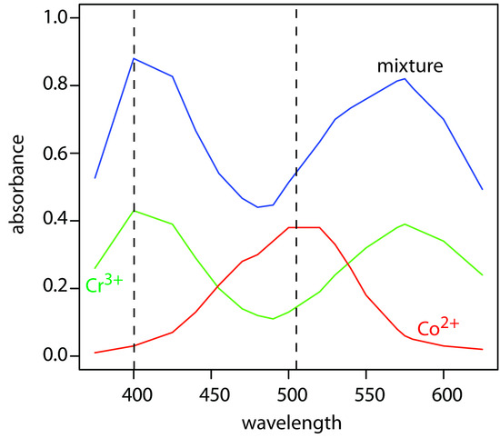
To obtain results with good accuracy and precision the two wavelengths should be selected so that εX > εY at one wavelength and εX < εY at the other wavelength. It is easy to appreciate why this is true. Because the absorbance at each wavelength is dominated by one analyte, any uncertainty in the concentration of the other analyte has less of an impact. Figure 10.35 shows that the choice of wavelengths for Practice Exercise 10.6 are reasonable. When the choice of wavelengths is not obvious, one method for locating the optimum wavelengths is to plot εX/εY as function of wavelength, and determine the wavelengths where εX/εY reaches maximum and minimum values.8
Note
For example, in Example 10.6 the molar absorptivity for Fe3+ at 550 nm is 119× that for Cu2+, and the molar absorptivity for Cu2+ at 396 nm is 10.2× that for Fe3+.
Figure 10.35 Visible absorption spectra for 0.0250 M Cr3+, 0.0750 M Co2+, and for a mixture of Cr3+ and Co2+. The two wavelengths used for analyzing the mixture of Cr3+ and Co2+ are shown by the dashed lines. The data for the two standard solutions are from reference 7.
When the analyte’s spectra overlap severely, such that εX ≈ εY at all wavelength, other computational methods may provide better accuracy and precision. In a multiwavelength linear regression analysis, for example, a mixture’s absorbance is compared to that for a set of standard solutions at several wavelengths.9 If ASX and ASY are the absorbance values for standard solutions of components X and Y at any wavelength, then
A_\ce{SX} = ε_\ce{X}bC_\ce{SX}\tag{10.13}
A_\ce{SY} = ε_\ce{Y}bC_\ce{SY}\tag{10.14}
where CSX and CSY are the known concentrations of X and Y in the standard solutions. Solving equation 10.13 and equation 10.14 for εX and εY, substituting into equation 10.11, and rearranging, gives
\dfrac{A_\ce{mix}}{A_\ce{SX}} = \dfrac{C_\ce{X}}{C_\ce{SX}} + \dfrac{C_\ce{Y}}{C_\ce{SY}} × \dfrac{A_\ce{SY}}{A_\ce{SX}}
To determine CX and CY the mixture’s absorbance and the absorbances of the standard solutions are measured at several wavelengths. Graphing Amix/ASX versus ASY/ASX gives a straight line with a slope of CY/CSY and a y-intercept of CX/CSX. This approach is particularly helpful when it is not possible to find wavelengths where εX > εY and εX < εY.
Note
The approach outlined here for a multiwavelength linear regression uses a single standard solution for each analyte. A more rigorous approach uses multiple standards for each analyte. The math behind the analysis of this data—what we call a multiple linear regression—is beyond the level of this text. For more details about multiple linear regression see Brereton, R. G. Chemometrics: Data Analysis for the Laboratory and Chemical Plant, Wiley: Chichester, England, 2003.
Figure 10.35 shows visible absorbance spectra for a standard solution of 0.0250 M Cr3+, a standard solution of 0.0750 M Co2+, and a mixture containing unknown concentrations of each ion. The data for these spectra are shown here.10
|
λ (nm) |
ACr |
ACo |
Amix |
λ (nm) |
ACr |
ACo |
Amix |
|
375 |
0.26 |
0.01 |
0.53 |
520 |
0.19 |
0.38 |
0.63 |
|
400 |
0.43 |
0.03 |
0.88 |
530 |
0.24 |
0.33 |
0.70 |
|
425 |
0.39 |
0.07 |
0.83 |
540 |
0.28 |
0.26 |
0.73 |
|
440 |
0.29 |
0.13 |
0.67 |
550 |
0.32 |
0.18 |
0.76 |
|
455 |
0.20 |
0.21 |
0.54 |
570 |
0.38 |
0.08 |
0.81 |
|
470 |
0.14 |
0.28 |
0.47 |
575 |
0.39 |
0.06 |
0.82 |
|
480 |
0.12 |
0.30 |
0.44 |
580 |
0.38 |
0.05 |
0.79 |
|
490 |
0.11 |
0.34 |
0.45 |
600 |
0.34 |
0.03 |
0.70 |
|
500 |
0.13 |
0.38 |
0.51 |
625 |
0.24 |
0.02 |
0.49 |
Use a multiwavelength regression analysis to determine the composition of the unknown.
Solution
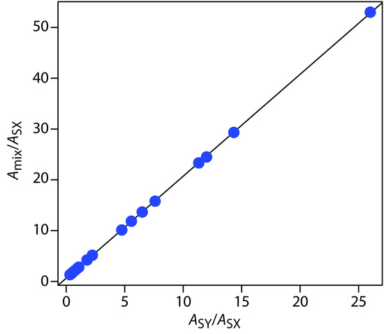
First we need to calculate values for Amix/ASX and for ASY/ASX. Let’s define X as Co2+ and Y as Cr3+. For example, at a wavelength of 375 nm Amix/ASX is 0.53/0.01, or 53 and ASY/ASX is 0.26/0.01, or 26. Completing the calculation for all wavelengths and graphing Amix/ASX versus ASY/ASXgives the result shown in Figure 10.36. Fitting a straight-line to the data gives a regression model of
\dfrac{A_\ce{mix}}{A_\ce{SX}} = 0.636 + 2.01 × \dfrac{A_\ce{SY}}{A_\ce{SX}}
Using the y-intercept, the concentration of Co2+ is
\dfrac{C_\ce{X}}{C_\ce{SX}} = \dfrac{C_\ce{Co}}{0.0750\: \ce M} = 0.636
or CCo = 0.048 M, and using the slope the concentration of Cr3+ is
\dfrac{C_\ce{Y}}{C_\ce{SY}} = \dfrac{C_\ce{Cr}}{0.0250\:\ce M} = 2.01
or CCr = 0.050 M.
Figure 10.36 Multiwavelength linear regression analysis for the data in Example 10.7.
A mixture of MnO4– and Cr2O72–, and standards of 0.10 mM KMnO4 and of 0.10 mM K2Cr2O7 gives the results shown in the following table. Determine the composition of the mixture. The data for this problem is from Blanco, M. C.; Iturriaga, H.; Maspoch, S.; Tarin, P. J. Chem. Educ. 1989, 66, 178–180.
|
λ (nm) |
AMn |
ACr |
Amix |
|
266 |
0.042 |
0.410 |
0.766 |
|
288 |
0.082 |
0.283 |
0.571 |
|
320 |
0.168 |
0.158 |
0.422 |
|
350 |
0.125 |
0.318 |
0.672 |
|
360 |
0.056 |
0.181 |
0.366 |
(There are many additional ways to analyze mixtures spectrophotometrically, including generalized standard additions, H-point standard additions, principal component regression to name a few. Consult the chapter’s additional resources for further information.)
Click here to review your answer to this exercise.
10.3.3 Qualitative Applications
As discussed earlier in Section 10.2.1, ultraviolet, visible, and infrared absorption bands result from the absorption of electromagnetic radiation by specific valence electrons or bonds. The energy at which the absorption occurs, and its intensity is determined by the chemical environment of the absorbing moiety. For example, benzene has several ultraviolet absorption bands due to π → π* transitions. The position and intensity of two of these bands, 203.5 nm (ε = 7400 M–1 cm–1) and 254 nm (ε = 204 M–1 cm–1), are sensitive to substitution. For benzoic acid, in which a carboxylic acid group replaces one of the aromatic hydrogens, the two bands shift to 230 nm (ε = 11 600 M–1 cm–1) and 273 nm (ε = 970 M–1 cm–1). A variety of rules have been developed to aid in correlating UV/Vis absorption bands to chemical structure. Similar correlations have been developed for infrared absorption bands. For example a carbonyl’s C=O stretch is sensitive to adjacent functional groups, occurring at 1650 cm–1 for acids, 1700 cm–1 for ketones, and 1800 cm–1 for acid chlorides. The interpretation of UV/Vis and IR spectra receives adequate coverage elsewhere in the chemistry curriculum, notably in organic chemistry, and is not considered further in this text.
With the availability of computerized data acquisition and storage it is possible to build digital libraries of standard reference spectra. The identity of an a unknown compound can often be determined by comparing its spectrum against a library of reference spectra, a process is known as spectral searching. Comparisons are made using an algorithm that calculates the cumulative difference between the sample’s spectrum and a reference spectrum. For example, one simple algorithm uses the following equation
D = \sum_{i=1}^{n} |(A_{sample})_i - (A_{reference})_i|
where D is the cumulative difference, Asample is the sample’s absorbance at wavelength or wavenumber i, Areference is the absorbance of the reference compound at the same wavelength or wavenumber, and n is the number of digitized points in the spectra. The cumulative difference is calculated for each reference spectrum. The reference compound with the smallest value of D provides the closest match to the unknown compound. The accuracy of spectral searching is limited by the number and type of compounds included in the library, and by the effect of the sample’s matrix on the spectrum.
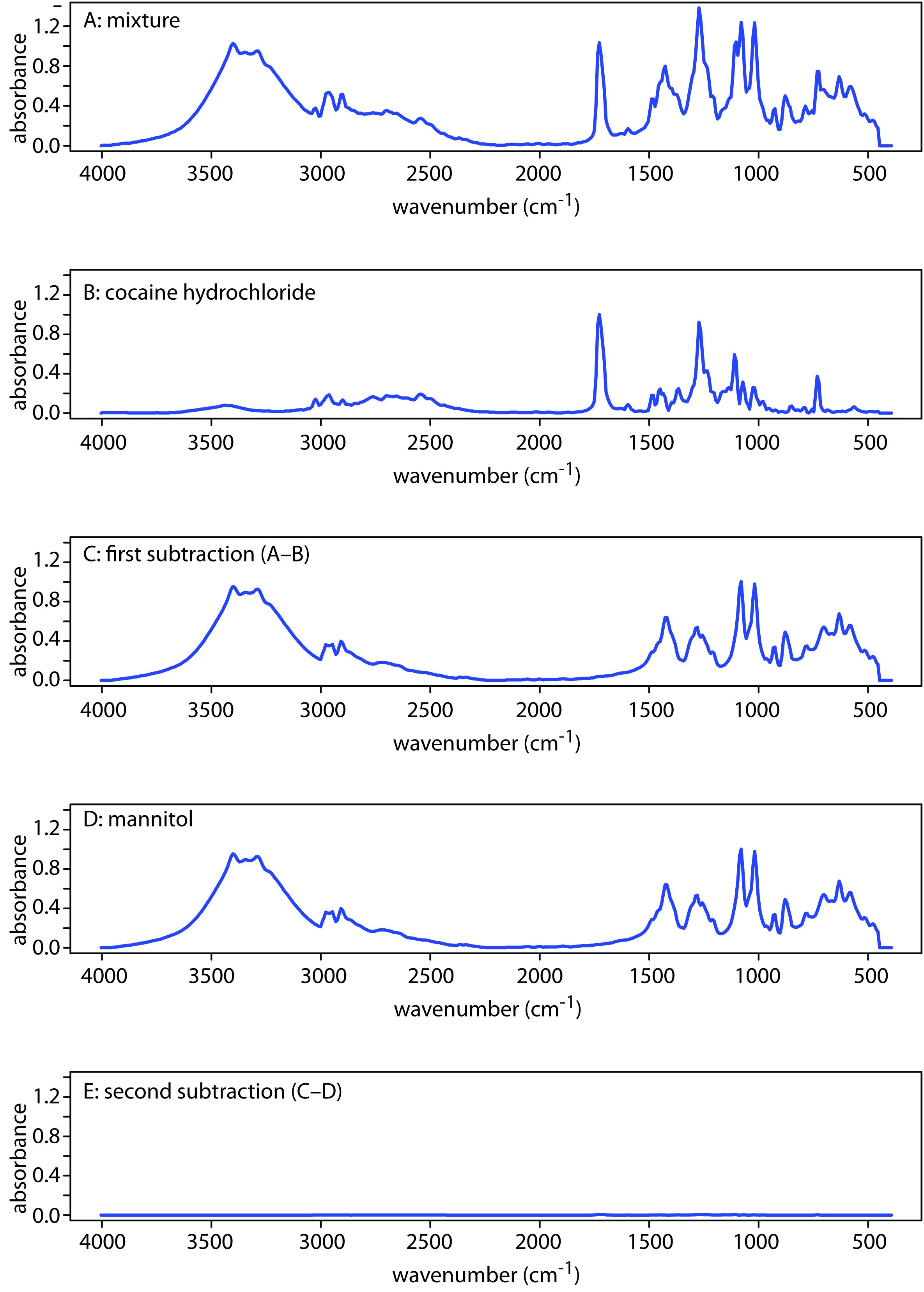
Another advantage of computerized data acquisition is the ability to subtract one spectrum from another. When coupled with spectral searching it may be possible, by repeatedly searching and subtracting reference spectra, to determine the identity of several components in a sample without the need of a prior separation step. An example is shown in Figure 10.37 in which the composition of a two-component mixture is determined by successive searching and subtraction. Figure 10.37a shows the spectrum of the mixture. A search of the spectral library selects cocaine . HCl (Figure 10.37b) as a likely component of the mixture. Subtracting the reference spectrum for cocaine . HCl from the mixture’s spectrum leaves a result (Figure 10.37c) that closely matches mannitol’s reference spectrum (Figure 10.37d). Subtracting the reference spectrum for leaves only a small residual signal (Figure 10.37e).
Figure 10.37 Identifying the components of a mixture by spectral searching and subtracting. (a) IR spectrum of the mixture; (b) Reference IR spectrum of cocaine . HCl; (c) Result of subtracting the spectrum of cocaine . HCl from the mixture’s spectrum; (d) Reference IR spectrum of mannitol; and (e) The residual spectrum after removing mannitol’s contribution to the mixture’s spectrum.
Note
IR spectra traditionally are displayed using percent transmittance, %T, along the y-axis (for example, see Figure 10.16). Because absorbance—not percent transmittance—is a linear function of concentration, spectral searching and spectral subtraction, is easier to do when displaying absorbance on the y-axis.
10.3.4 Characterization Applications
Molecular absorption, particularly in the UV/Vis range, has been used for a variety of different characterization studies, including determining the stoichiometry of metal–ligand complexes and determining equilibrium constants. Both of these examples are examined in this section.
Stoichiometry of a Metal-Ligand Complex
We can determine the stoichiometry of a metal–ligand complexation reaction
\mathrm{M + \mathit{y}L ⇋ ML_\mathit{y}}
using one of three methods: the method of continuous variations, the mole-ratio method, and the slope-ratio method. Of these approaches, the method of continuous variations, also called Job’s method, is the most popular. In this method a series of solutions is prepared such that the total moles of metal and ligand, ntotal, in each solution is the same. If (nM)i and (nL)i are, respectively, the moles of metal and ligand in solution i, then
n_\ce{total}= (n_\ce{M})_i + (n_\ce{L})_i
The relative amount of ligand and metal in each solution is expressed as the mole fraction of ligand, (XL)i, and the mole fraction of metal, (XM)i,
(X_\ce{L})_i = \dfrac{(n_\ce{L})_i}{n_\ce{total}}
(X_\ce{M})_i = 1 − \dfrac{(n_\ce{L})_i}{n_\ce{total}} = \dfrac{(n_\ce{M})_i}{n_\ce{total}}
The concentration of the metal–ligand complex in any solution is determined by the limiting reagent, with the greatest concentration occurring when the metal and the ligand are mixed stoichiometrically. If we monitor the complexation reaction at a wavelength where only the metal–ligand complex absorbs, a graph of absorbance versus the mole fraction of ligand will have two linear branches—one when the ligand is the limiting reagent and a second when the metal is the limiting reagent. The intersection of these two branches represents a stoichiometric mixing of the metal and the ligand. We can use the mole fraction of ligand at the intersection to determine the value of y for the metal–ligand complex MLy.
y = \dfrac{n_\ce{L}}{n_\ce{M}} = \dfrac{X_\ce{L}}{X_\ce{M}} = \dfrac{X_\ce{L}}{1 − X_\ce{L}}
Note
You also can plot the data as absorbance versus the mole fraction of metal. In this case, y is equal to (1–XM)/XM.
To determine the formula for the complex between Fe2+ and o-phenanthroline, a series of solutions is prepared in which the total concentration of metal and ligand is held constant at 3.15 × 10⁻⁴ M. The absorbance of each solution is measured at a wavelength of 510 nm. Using the following data, determine the formula for the complex.
|
XL |
absorbance |
XL |
absorbance |
|
0.000 |
0.000 |
0.600 |
0.693 |
|
0.100 |
0.116 |
0.700 |
0.809 |
|
0.200 |
0.231 |
0.800 |
0.693 |
|
0.300 |
0.347 |
0.900 |
0.347 |
|
0.400 |
0.462 |
1.000 |
0.000 |
|
0.500 |
0.578 |
|
|
(To prepare the solutions for this example I first prepared a solution of 3.15 × 10⁻⁴ M Fe2+ and a solution of 3.15 × 10⁻⁴ M o-phenanthroline. Because the two stock solutions are of equal concentration, diluting a portion of one solution with the other solution gives a mixture in which the combined concentration of o-phenanthroline and Fe2+ is 3.15 × 10⁻⁴ M. If each solution has the same volume, then each solution contains the same total moles of metal and ligand.)
Solution
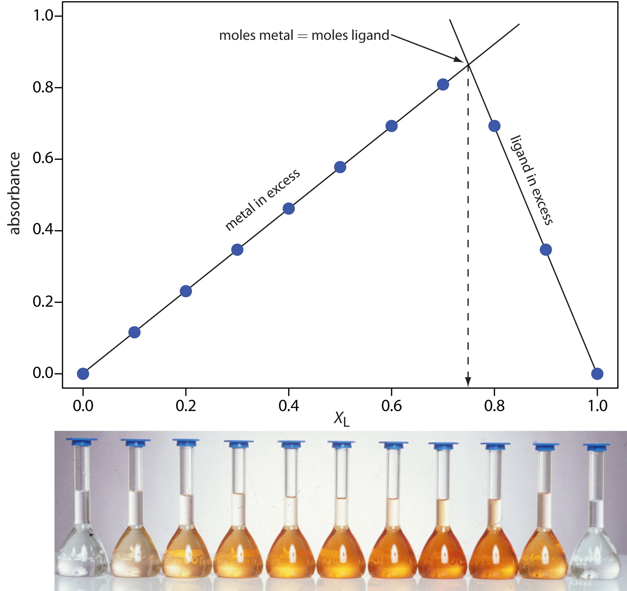
A plot of absorbance versus the mole fraction of ligand is shown in Figure 10.38. To find the maximum absorbance, we extrapolate the two linear portions of the plot. The two lines intersect at a mole fraction of ligand of 0.75. Solving for y gives
y = \dfrac{X_\ce{L}}{1 – X_\ce{L}} = \dfrac{0.75}{1 – 0.75} = 3
The formula for the metal–ligand complex is Fe(o-phenanthroline)32+.
Figure 10.38 Continuous variations plot for Example 10.8. The photo shows the solutions used in gathering the data. Each solution is displayed directly below its corresponding point on the continuous variations plot.
Use the continuous variations data in the following table to determine the formula for the complex between Fe2+ and SCN–. The data for this problem is adapted from Meloun, M.; Havel, J.; Högfeldt, E. Computation of Solution Equilibria, Ellis Horwood: Chichester, England, 1988, p. 236.
|
XL |
absorbance |
XL |
absorbance |
XL |
absorbance |
XL |
absorbance |
|
0.0200 |
0.068 |
0.2951 |
0.670 |
0.5811 |
0.790 |
0.8923 |
0.325 |
|
0.0870 |
0.262 |
0.3887 |
0.767 |
0.6860 |
0.701 |
0.9787 |
0.071 |
|
0.1792 |
0.471 |
0.4964 |
0.807 |
0.7885 |
0.540 |
|
|
Click here to review your answer to this exercise.
Several precautions are necessary when using the method of continuous variations. First, the metal and the ligand must form only one metal–ligand complex. To determine if this condition is true, plots of absorbance versus XL are constructed at several different wavelengths and for several different values of ntotal. If the maximum absorbance does not occur at the same value of XL for each set of conditions, then more than one metal–ligand complex must be present. A second precaution is that the metal–ligand complex’s absorbance must obey Beer’s law. Third, if the metal–ligand complex’s formation constant is relatively small, a plot of absorbance versus XL may show significant curvature. In this case it is often difficult to determine the stoichiometry by extrapolation. Finally, because the stability of a metal–ligand complex may be influenced by solution conditions, the composition of the solutions must be carefully controlled. When the ligand is a weak base, for example, the solutions must be buffered to the same pH.
In the mole-ratio method the amount of one reactant, usually the moles of metal, is held constant, while the amount of the other reactant is varied. The absorbance is monitored at a wavelength where the metal–ligand complex absorbs. A plot of absorbance as a function of the ligand-to-metal mole ratio, nL/nM, has two linear branches, which intersect at a mole–ratio corresponding to the complex’s formula. Figure 10.39a shows a mole-ratio plot for the formation of a 1:1 complex in which the absorbance is monitored at a wavelength where only the complex absorbs. Figure 10.39b shows a mole-ratio plot for a 1:2 complex in which all three species—the metal, the ligand, and the complex—absorb at the selected wavelength. Unlike the method of continuous variations, the mole-ratio method can be used for complexation reactions that occur in a stepwise fashion if there is a difference in the molar absorptivities of the metal–ligand complexes, and if the formation constants are sufficiently different. A typical mole-ratio plot for the step-wise formation of ML and ML2 is shown in Figure 10.39c.
Figure 10.39 Mole-ratio plots for: (a) a 1:1 metal–ligand complex in which only the complex absorbs; (b) a 1:2 metal–ligand complex in which the metal, the ligand, and the complex absorb; and (c) the stepwise formation of a 1:1 and a 1:2 metal–ligand complex.
In both the method of continuous variations and the mole-ratio method we determine the complex’s stoichiometry by extrapolating absorbance data from conditions in which there is a linear relationship between absorbance and the relative amounts of metal and ligand. If a metal–ligand complex is very weak, a plot of absorbance versus XL or nL/nM may be so curved that it is impossible to determine the stoichiometry by extrapolation. In this case the slope-ratio may be used.
In the slope-ratio method two sets of solutions are prepared. The first set of solutions contains a constant amount of metal and a variable amount of ligand, chosen such that the total concentration of metal, CM, is much larger than the total concentration of ligand, CL. Under these conditions we may assume that essentially all the ligand reacts in forming the metal–ligand complex. The concentration of the complex, which has the general form MxLy, is
[M_\ce{x}L_\ce{y}] = \dfrac{C_\ce{L}}{y}
If we monitor the absorbance at a wavelength where only MxLy absorbs, then
A = εb[M_\ce{x}L_\ce{y}] = \dfrac{εbC_\ce{L}}{y}
and a plot of absorbance versus CL is linear with a slope, sL, of
s_\ce{L} = \dfrac{εb}{y}
A second set of solutions is prepared with a fixed concentration of ligand that is much greater than a variable concentration of metal; thus
[M_\ce{x}L_\ce{y}] = \dfrac{C_\ce{M}}{x}
A = εb[M_\ce{x}L_\ce{y}] = \dfrac{εbC_\ce{M}}{x}
s_\ce{M} = \dfrac{εb}{x}
A ratio of the slopes provides the relative values of x and y.
\dfrac{s_\ce{M}}{s_\ce{L}} = \dfrac{εb / x}{εb / y} = \dfrac{y}{x}
An important assumption in the slope-ratio method is that the complexation reaction continues to completion in the presence of a sufficiently large excess of metal or ligand. The slope-ratio method also is limited to systems in which only a single complex is formed and for which Beer’s law is obeyed.
Determination of Equilibrium Constants
Another important application of molecular absorption spectroscopy is the determination of equilibrium constants. Let’s consider, as a simple example, an acid–base reaction of the general form
\ce{HIn}(aq) + \ce{H2O}(l) ⇋ \ce{H3O+}(aq) + \ce{In-}(aq)
where HIn and In– are the conjugate weak acid and weak base forms of an acid–base indicator. The equilibrium constant for this reaction is
\mathrm{\mathit{K}_a = \dfrac{[H_3O^+] [In^-]}{[HIn]}}
To determine the equilibrium constant’s value, we prepare a solution in which the reaction is in a state of equilibrium and determine the equilibrium concentration of H3O+, HIn, and In–. The concentration of H3O+ is easy to determine by simply measuring the solution’s pH. To determine the concentration of HIn and In– we can measure the solution’s absorbance.
If both HIn and In– absorb at the selected wavelength, then, from equation 10.6, we know that
A = ε_\ce{HIn}b[\ce{HIn}] + ε_\ce{In}b[\ce{In-}]\tag{10.15}
where εHIn and εIn are the molar absorptivities for HIn and In–. The total concentration of indicator, C, is given by a mass balance equation
C = \mathrm{[HIn] + [In^-]}\tag{10.16}
Solving equation 10.16 for [HIn] and substituting into equation 10.15 gives
A = ε_\ce{HIn}b(C − [\ce{In-}]) + ε_\ce{In}b[\ce{In-}]
which we simplify to
A = ε_\ce{HIn}bC − ε_\ce{HIn}b[\ce{In-}] + ε_\ce{In}b[\ce{In-}]
A = A_\ce{HIn}+ b[\ce{In-}](ε_\ce{In} - ε_\ce{HIn})\tag{10.17}
where AHIn, which is equal to εHInbC, is the absorbance when the pH is acidic enough that essentially all the indicator is present as HIn. Solving equation 10.17 for the concentration of In– gives
[\ce{In-}] = \dfrac{A − A_\ce{HIn}}{b(ε_\ce{In} − ε_\ce{HIn})}\tag{10.18}
Proceeding in the same fashion, we can derive a similar equation for the concentration of HIn
[\ce{HIn}] = \dfrac{A_\ce{In} − A}{b(ε_\ce{In} − ε_\ce{HIn})}\tag{10.19}
where AIn, which is equal to εInbC, is the absorbance when the pH is basic enough that only In– contributes to the absorbance. Substituting equation 10.18 and equation 10.19 into the equilibrium constant expression for HIn gives
K_a = [\ce{H3O+}]\dfrac{A − A_\ce{HIn}}{A_\ce{In} − A}\tag{10.20}
We can use equation 10.20 to determine the value of Ka in one of two ways. The simplest approach is to prepare three solutions, each of which contains the same amount, C, of indicator. The pH of one solution is made sufficiently acidic such that [HIn] >> [In−]. The absorbance of this solution gives AHIn. The value of AIn is determined by adjusting the pH of the second solution such that [In−] >> [HIn]. Finally, the pH of the third solution is adjusted to an intermediate value, and the pH and absorbance, A, recorded. The value of Ka is calculated using equation 10.20.
The acidity constant for an acid–base indicator is determined by preparing three solutions, each of which has a total indicator concentration of 5.00 × 10⁻⁵ M. The first solution is made strongly acidic with HCl and has an absorbance of 0.250. The second solution was made strongly basic and has an absorbance of 1.40. The pH of the third solution is 2.91 and has an absorbance of 0.662. What is the value of Ka for the indicator?
Solution
The value of Ka is determined by making appropriate substitutions into 10.20; thus
K_\ce{a}= (1.23×10^{−3}) × \dfrac{0.662 − 0.250}{1.40 − 0.662} = 6.87×10^{−4}
To determine the Ka of a merocyanine dye, the absorbance of a solution of 3.5×10⁻⁴ M dye was measured at a pH of 2.00, a pH of 6.00, and a pH of 12.00, yielding absorbances of 0.000, 0.225, and 0.680, respectively. What is the value of Ka for this dye? The data for this problem is adapted from Lu, H.; Rutan, S. C. Anal. Chem., 1996, 68, 1381–1386.
Click here to review your answer to this exercise.
A second approach for determining Ka is to prepare a series of solutions, each containing the same amount of indicator. Two solutions are used to determine values for AHIn and AIn. Taking the log of both sides of equation 10.20 and rearranging leave us with the following equation.
\log\dfrac{A − A_\ce{HIn}}{A_\ce{In} − A} = \mathrm{pH − p\mathit{K}_a}\tag{10.21}
A plot of log[(A – AHIn)/(AIn – A)] versus pH is a straight-line with a slope of +1 and a y-intercept of –pKa.
To determine the Ka of the indicator bromothymol blue, the absorbance of a series of solutions containing the same concentration of the indicator was measured at pH levels of 3.35, 3.65, 3.94, 4.30, and 4.64, yielding absorbances of 0.170, 0.287, 0.411, 0.562, and 0.670, respectively. Acidifying the first solution to a pH of 2 changes its absorbance to 0.006, and adjusting the pH of the last solution to 12 changes its absorbance to 0.818. What is the value of Ka for this day? The data for this problem is from Patterson, G. S. J. Chem. Educ., 1999, 76, 395–398.
Click here to review your answer to this exercise.
In developing these approaches for determining Ka we considered a relatively simple system in which the absorbance of HIn and In– are easy to measure and for which it is easy to determine the concentration of H3O+. In addition to acid–base reactions, we can adapt these approaches to any reaction of the general form
\ce{X}(aq) + \ce{Y}(aq) ⇋ \ce{Z}(aq)
including metal–ligand complexation reactions and redox reactions, provided that we can determine spectrophotometrically the concentration of the product, Z, and one of the reactants, and that the concentration of the other reactant can be measured by another method. With appropriate modifications, more complicated systems, in which one or more of these parameters can not be measured, also can be treated.11
10.3.5 Evaluation of UV/Vis and IR Spectroscopy
Scale of Operation
Molecular UV/Vis absorption is routinely used for the analysis of trace analytes in macro and meso samples. Major and minor analytes can be determined by diluting the sample before analysis, while concentrating a sample may allow for the analysis of ultratrace analytes. The scale of operations for infrared absorption is generally poorer than that for UV/Vis absorption.
Note
See Figure 3.5 to review the meaning of macro and meso for describing samples, and the meaning of major, minor, and ultratrace for describing analytes.
Accuracy
Under normal conditions a relative error of 1–5% is easy to obtained with UV/Vis absorption. Accuracy is usually limited by the quality of the blank. Examples of the type of problems that may be encountered include the presence of particulates in a sample that scatter radiation and interferents that react with analytical reagents. In the latter case the interferent may react to form an absorbing species, giving rise to a positive determinate error. Interferents also may prevent the analyte from reacting, leading to a negative determinate error. With care, it may be possible to improve the accuracy of an analysis by as much as an order of magnitude.
Precision
In absorption spectroscopy, precision is limited by indeterminate errors—primarily instrumental noise—introduced when measuring absorbance. Precision is generally worse for low absorbances where P0 ≈ PT, and for high absorbances when PT approaches 0. We might expect, therefore, that precision will vary with transmittance.
We can derive an expression between precision and transmittance by applying the propagation of uncertainty as described in Chapter 4. To do so we rewrite Beer’s law as
C = −\dfrac{1}{εb}\log T\tag{10.22}
Table 4.10 in Chapter 4 helps us in completing the propagation of uncertainty for equation 10.22, giving the absolute uncertainty in the concentration, sC, as
s_\ce{C}= −\dfrac{0.4343}{εb} × \dfrac{s_\ce{T}}{T}\tag{10.23}
where sT is the absolute uncertainty in the transmittance. Dividing equation 10.23 by equation 10.22 gives the relative uncertainty in concentration, sC/C, as
\dfrac{s_\ce{C}}{C} = \dfrac{0.4343s_\ce{T}}{T \log T}
If we know the absolute uncertainty in transmittance, we can determine the relative uncertainty in concentration for any transmittance.
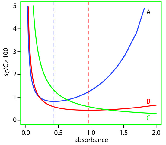
Determining the relative uncertainty in concentration is complicated because sT may be a function of the transmittance. As shown in Table 10.8, three categories of indeterminate instrumental error have been observed.12 A constant sT is observed for the uncertainty associated with reading %T on a meter’s analog or digital scale. Typical values are ±0.2–0.3% (a k1 of ±0.002–0.003) for an analog scale, and ±0.001% a (k1 of ±0.000 01) for a digital scale. A constant sT also is observed for the thermal transducers used in infrared spectrophotometers. The effect of a constant sT on the relative uncertainty in concentration is shown by curve A in Figure 10.40. Note that the relative uncertainty is very large for both high and low absorbances, reaching a minimum when the absorbance is 0.4343. This source of indeterminate error is important for infrared spectrophotometers and for inexpensive UV/Vis spectrophotometers. To obtain a relative uncertainty in concentration of ±1–2%, the absorbance must be kept within the range 0.1–1.
| Category | Sources of Indeterminate Error | Relative Uncertainty in Concentration |
|---|---|---|
|
s_\ce{T} = k_1 |
%T readout resolution noise in thermal detectors |
\dfrac{s_\ce{C}}{C} = \dfrac{0.4343k_1}{T \log T} |
| s_\ce{T}= k_2\sqrt{T^2 + T} | noise in photon detectors |
\dfrac{s_\ce{C}}{C} = \dfrac{0.4343k_2}{\log T}\sqrt{1 + \dfrac{1}{T}} |
|
s_\ce{T}= k_3T |
positioning of sample cell fluctuations in source intensity |
\dfrac{s_\ce{C}}{C} = \dfrac{0.4343k_3}{\log T} |
Values of sT are a complex function of transmittance when indeterminate errors are dominated by the noise associated with photon detectors. Curve B in Figure 10.40 shows that the relative uncertainty in concentration is very large for low absorbances, but is less at higher absorbances. Although the relative uncertainty reaches a minimum when the absorbance is 0.963, there is little change in the relative uncertainty for absorbances within the range 0.5–2. This source of indeterminate error generally limits the precision of high quality UV/Vis spectrophotometers for mid-to-high absorbances.
Figure 10.40 Percent relative uncertainty in concentration as a function of absorbance for the categories of indeterminate errors in Table 10.8. A: k1 = ±0.0030; B: k2 = ±0.0030; C:k3 = ±0.0130. The dashed lines correspond to the minimum uncertainty for curve A (absorbance of 0.4343) and for curve B (absorbance of 0.963).
Finally, the value of sT is directly proportional to transmittance for indeterminate errors resulting from fluctuations in the source’s intensity and from uncertainty in positioning the sample within the spectrometer. The latter is particularly important because the optical properties of any sample cell are not uniform. As a result, repositioning the sample cell may lead to a change in the intensity of transmitted radiation. As shown by curve C in Figure 10.40, the effect is only important at low absorbances. This source of indeterminate errors is usually the limiting factor for high quality UV/Vis spectrophotometers when the absorbance is relatively small.
When the relative uncertainty in concentration is limited by the %T readout resolution, the precision of the analysis can be improved by redefining 100% T and 0% T. Normally 100% T is established using a blank and 0% T is established while preventing the source’s radiation from reaching the detector. If the absorbance is too high, precision can be improved by resetting 100% T using a standard solution of the analyte whose concentration is less than that of the sample (Figure 10.41a). For a sample whose absorbance is too low, precision can be improved by redefining 0% T using a standard solution of the analyte whose concentration is greater than that of the analyte (Figure 10.41b). In this case a calibration curve is required because a linear relationship between absorbance and concentration no longer exists. Precision can be further increased by combining these two methods (Figure 10.41c). Again, a calibration curve is necessary since the relationship between absorbance and concentration is no longer linear.
Figure 10.41 Methods for improving the precision of absorption methods: (a) high-absorbance method; (b) low-absorbance method; (c) maximum precision method.
Sensitivity
The sensitivity of a molecular absorption method, which is the slope of a Beer’s law calibration curve, is the product of the analyte’s absorptivity and the pathlength of the sample cell (εb). You can improve a method’s sensitivity by selecting a wavelength where absorbance is at a maximum or by increasing the pathlength.
Note
See Figure 10.24 for an example of how the choice of wavelength affects a calibration curve’s sensitivity.
Selectivity
Selectivity is rarely a problem in molecular absorption spectrophotometry. In many cases it is possible to find a wavelength where only the analyte absorbs. When two or more species do contribute to the measured absorbance, a multicomponent analysis is still possible, as shown in Example 10.6 and Example 10.7.
Time, Cost, and Equipment
The analysis of a sample by molecular absorption spectroscopy is relatively rapid, although additional time may be required if we need to chemically convert a nonabsorbing analyte into an absorbing form. The cost of UV/Vis instrumentation ranges from several hundred dollars for a simple filter photometer, to more than $50,000 for a computer controlled high resolution, double-beam instrument equipped with variable slits, and operating over an extended range of wavelengths. Fourier transform infrared spectrometers can be obtained for as little as $15,000–$20,000, although more expensive models are available.


