
5.7: Visualizing TLC Plates
- Page ID
- 536799
\( \newcommand{\vecs}[1]{\overset { \scriptstyle \rightharpoonup} {\mathbf{#1}} } \)
\( \newcommand{\vecd}[1]{\overset{-\!-\!\rightharpoonup}{\vphantom{a}\smash {#1}}} \)
\( \newcommand{\dsum}{\displaystyle\sum\limits} \)
\( \newcommand{\dint}{\displaystyle\int\limits} \)
\( \newcommand{\dlim}{\displaystyle\lim\limits} \)
\( \newcommand{\id}{\mathrm{id}}\) \( \newcommand{\Span}{\mathrm{span}}\)
( \newcommand{\kernel}{\mathrm{null}\,}\) \( \newcommand{\range}{\mathrm{range}\,}\)
\( \newcommand{\RealPart}{\mathrm{Re}}\) \( \newcommand{\ImaginaryPart}{\mathrm{Im}}\)
\( \newcommand{\Argument}{\mathrm{Arg}}\) \( \newcommand{\norm}[1]{\| #1 \|}\)
\( \newcommand{\inner}[2]{\langle #1, #2 \rangle}\)
\( \newcommand{\Span}{\mathrm{span}}\)
\( \newcommand{\id}{\mathrm{id}}\)
\( \newcommand{\Span}{\mathrm{span}}\)
\( \newcommand{\kernel}{\mathrm{null}\,}\)
\( \newcommand{\range}{\mathrm{range}\,}\)
\( \newcommand{\RealPart}{\mathrm{Re}}\)
\( \newcommand{\ImaginaryPart}{\mathrm{Im}}\)
\( \newcommand{\Argument}{\mathrm{Arg}}\)
\( \newcommand{\norm}[1]{\| #1 \|}\)
\( \newcommand{\inner}[2]{\langle #1, #2 \rangle}\)
\( \newcommand{\Span}{\mathrm{span}}\) \( \newcommand{\AA}{\unicode[.8,0]{x212B}}\)
\( \newcommand{\vectorA}[1]{\vec{#1}} % arrow\)
\( \newcommand{\vectorAt}[1]{\vec{\text{#1}}} % arrow\)
\( \newcommand{\vectorB}[1]{\overset { \scriptstyle \rightharpoonup} {\mathbf{#1}} } \)
\( \newcommand{\vectorC}[1]{\textbf{#1}} \)
\( \newcommand{\vectorD}[1]{\overrightarrow{#1}} \)
\( \newcommand{\vectorDt}[1]{\overrightarrow{\text{#1}}} \)
\( \newcommand{\vectE}[1]{\overset{-\!-\!\rightharpoonup}{\vphantom{a}\smash{\mathbf {#1}}}} \)
\( \newcommand{\vecs}[1]{\overset { \scriptstyle \rightharpoonup} {\mathbf{#1}} } \)
\(\newcommand{\longvect}{\overrightarrow}\)
\( \newcommand{\vecd}[1]{\overset{-\!-\!\rightharpoonup}{\vphantom{a}\smash {#1}}} \)
\(\newcommand{\avec}{\mathbf a}\) \(\newcommand{\bvec}{\mathbf b}\) \(\newcommand{\cvec}{\mathbf c}\) \(\newcommand{\dvec}{\mathbf d}\) \(\newcommand{\dtil}{\widetilde{\mathbf d}}\) \(\newcommand{\evec}{\mathbf e}\) \(\newcommand{\fvec}{\mathbf f}\) \(\newcommand{\nvec}{\mathbf n}\) \(\newcommand{\pvec}{\mathbf p}\) \(\newcommand{\qvec}{\mathbf q}\) \(\newcommand{\svec}{\mathbf s}\) \(\newcommand{\tvec}{\mathbf t}\) \(\newcommand{\uvec}{\mathbf u}\) \(\newcommand{\vvec}{\mathbf v}\) \(\newcommand{\wvec}{\mathbf w}\) \(\newcommand{\xvec}{\mathbf x}\) \(\newcommand{\yvec}{\mathbf y}\) \(\newcommand{\zvec}{\mathbf z}\) \(\newcommand{\rvec}{\mathbf r}\) \(\newcommand{\mvec}{\mathbf m}\) \(\newcommand{\zerovec}{\mathbf 0}\) \(\newcommand{\onevec}{\mathbf 1}\) \(\newcommand{\real}{\mathbb R}\) \(\newcommand{\twovec}[2]{\left[\begin{array}{r}#1 \\ #2 \end{array}\right]}\) \(\newcommand{\ctwovec}[2]{\left[\begin{array}{c}#1 \\ #2 \end{array}\right]}\) \(\newcommand{\threevec}[3]{\left[\begin{array}{r}#1 \\ #2 \\ #3 \end{array}\right]}\) \(\newcommand{\cthreevec}[3]{\left[\begin{array}{c}#1 \\ #2 \\ #3 \end{array}\right]}\) \(\newcommand{\fourvec}[4]{\left[\begin{array}{r}#1 \\ #2 \\ #3 \\ #4 \end{array}\right]}\) \(\newcommand{\cfourvec}[4]{\left[\begin{array}{c}#1 \\ #2 \\ #3 \\ #4 \end{array}\right]}\) \(\newcommand{\fivevec}[5]{\left[\begin{array}{r}#1 \\ #2 \\ #3 \\ #4 \\ #5 \\ \end{array}\right]}\) \(\newcommand{\cfivevec}[5]{\left[\begin{array}{c}#1 \\ #2 \\ #3 \\ #4 \\ #5 \\ \end{array}\right]}\) \(\newcommand{\mattwo}[4]{\left[\begin{array}{rr}#1 \amp #2 \\ #3 \amp #4 \\ \end{array}\right]}\) \(\newcommand{\laspan}[1]{\text{Span}\{#1\}}\) \(\newcommand{\bcal}{\cal B}\) \(\newcommand{\ccal}{\cal C}\) \(\newcommand{\scal}{\cal S}\) \(\newcommand{\wcal}{\cal W}\) \(\newcommand{\ecal}{\cal E}\) \(\newcommand{\coords}[2]{\left\{#1\right\}_{#2}}\) \(\newcommand{\gray}[1]{\color{gray}{#1}}\) \(\newcommand{\lgray}[1]{\color{lightgray}{#1}}\) \(\newcommand{\rank}{\operatorname{rank}}\) \(\newcommand{\row}{\text{Row}}\) \(\newcommand{\col}{\text{Col}}\) \(\renewcommand{\row}{\text{Row}}\) \(\newcommand{\nul}{\text{Nul}}\) \(\newcommand{\var}{\text{Var}}\) \(\newcommand{\corr}{\text{corr}}\) \(\newcommand{\len}[1]{\left|#1\right|}\) \(\newcommand{\bbar}{\overline{\bvec}}\) \(\newcommand{\bhat}{\widehat{\bvec}}\) \(\newcommand{\bperp}{\bvec^\perp}\) \(\newcommand{\xhat}{\widehat{\xvec}}\) \(\newcommand{\vhat}{\widehat{\vvec}}\) \(\newcommand{\uhat}{\widehat{\uvec}}\) \(\newcommand{\what}{\widehat{\wvec}}\) \(\newcommand{\Sighat}{\widehat{\Sigma}}\) \(\newcommand{\lt}{<}\) \(\newcommand{\gt}{>}\) \(\newcommand{\amp}{&}\) \(\definecolor{fillinmathshade}{gray}{0.9}\)Organic compounds most commonly appear colorless on the white background of a TLC plate, which means that after running a TLC, chemists often cannot simply see where compounds are located. The compounds have to be "visualized" after elution, which means to temporarily convert them into something visible.
Ultraviolet Absorption
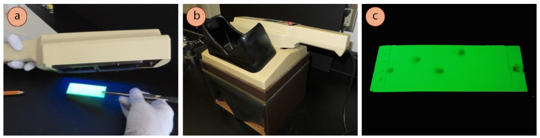
The most common non-destructive visualization method for TLC plates is ultraviolet (UV) light. A UV lamp can be used to shine either short-waved (254 nm) or long-waved (365 nm) ultraviolet light on a TLC plate with the touch of a button. Most commercially bought TLC plates contain a fluorescent material (e.g. zinc sulfide) in the silica or alumina, so the background of the plate will appear green when viewing with short-waved UV light. If a compound absorbs 254 nm UV light, it will appear dark, as the compound prevents the fluorescent material from receiving the UV light.
This method is so quick and easy that it is often the first visualization method tried. It is most useful for visualizing aromatic compounds and highly conjugated systems, as these strongly absorb UV. Since the compounds remain unchanged after viewing with UV light, a further visualization technique can be used afterwards on the same plate.
Procedure for UV visualization of TLC plate:
- Use a UV lamp to look at your developed TLC plate by pressing the short-waved button. Safety note: Care should be taken to never look directly at the UV source, and to minimize exposure to eyes.
- The plate background will appear green under short-waved UV light, and UV-active compounds will appear dark. Use a pencil to lightly circle spots, as they will disappear when the UV light is removed.
- Some compounds themselves fluoresce, appearing a variety of colors when exposed to either short- or long-waved UV light (bright purple or blue is the most common). Record these types of observations in your notebook if you see them, as they are rare, and are therefore an excellent identification tool.
Iodine
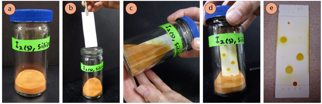
A commonly used semi-destructive visualization method is to expose a developed TLC plate to iodine (I2) vapor. An "iodine chamber" can be created by adding a few iodine crystals to a TLC chamber, or by adding a few iodine crystals to a chamber containing a portion of powdered silica or alumina. When a developed TLC plate is placed in the chamber and capped, the iodine sublimes and reacts with the compounds on the plate, forming yellow-brown spots. The coloration occurs because iodine forms colored complexes with many organic compounds.
Procedure for visualization of TLC plate with iodine:
- If not already prepared, make an "iodine chamber": in a fume hood, place a few centimeters of powdered silica or alumina in a screw-capped TLC chamber and add a few crystals of solid iodine (safety note: silica and alumina are lung irritants, and iodine vapor is considered an irritant and toxic). Let the silica or alumina and iodine sit together for a while with periodic swirling, and eventually the powder will become orange from adsorbing the iodine vapor.
- In a fume hood, place the developed TLC plate in the iodine chamber with forceps and close the lid. Gently shake the chamber to bury the TLC plate in the iodine-stained silica or alumina until the spots become colored. Many spots will appear yellow-brown almost immediately, and may darken with extended time.
- Promptly record appropriate observations of the TLC in your notebook, or circle the spots with a pencil, as the colors will soon fade as the iodine evaporates from the plate.
Chemical Stains
There are a variety of destructive visualization methods that can turn colorless compounds on a TLC plate into colored spots. A plate is either sprayed with or dipped in a reagent that undergoes a chemical reaction with a compound on the TLC plate to convert it into a colored compound, enabling the spot to be seen with the naked eye. Since a chemical reaction is occurring in the process, it is common to gently heat a plate after exposure to the reagent to speed up the reaction, although this may be unnecessary with some stains. Not every compound can be visualized with every reagent if they do not react together, and stains are often designed to work with only certain functional groups. The specific stain should be chosen based on the presumed structure of the compounds you want to visualize.
Adapted from Visualizing the Plates by Lisa Nichols.