9.5 Driving Reactant-Favored Reactions Using Electricity
- Page ID
- 163847
\( \newcommand{\vecs}[1]{\overset { \scriptstyle \rightharpoonup} {\mathbf{#1}} } \)
\( \newcommand{\vecd}[1]{\overset{-\!-\!\rightharpoonup}{\vphantom{a}\smash {#1}}} \)
\( \newcommand{\id}{\mathrm{id}}\) \( \newcommand{\Span}{\mathrm{span}}\)
( \newcommand{\kernel}{\mathrm{null}\,}\) \( \newcommand{\range}{\mathrm{range}\,}\)
\( \newcommand{\RealPart}{\mathrm{Re}}\) \( \newcommand{\ImaginaryPart}{\mathrm{Im}}\)
\( \newcommand{\Argument}{\mathrm{Arg}}\) \( \newcommand{\norm}[1]{\| #1 \|}\)
\( \newcommand{\inner}[2]{\langle #1, #2 \rangle}\)
\( \newcommand{\Span}{\mathrm{span}}\)
\( \newcommand{\id}{\mathrm{id}}\)
\( \newcommand{\Span}{\mathrm{span}}\)
\( \newcommand{\kernel}{\mathrm{null}\,}\)
\( \newcommand{\range}{\mathrm{range}\,}\)
\( \newcommand{\RealPart}{\mathrm{Re}}\)
\( \newcommand{\ImaginaryPart}{\mathrm{Im}}\)
\( \newcommand{\Argument}{\mathrm{Arg}}\)
\( \newcommand{\norm}[1]{\| #1 \|}\)
\( \newcommand{\inner}[2]{\langle #1, #2 \rangle}\)
\( \newcommand{\Span}{\mathrm{span}}\) \( \newcommand{\AA}{\unicode[.8,0]{x212B}}\)
\( \newcommand{\vectorA}[1]{\vec{#1}} % arrow\)
\( \newcommand{\vectorAt}[1]{\vec{\text{#1}}} % arrow\)
\( \newcommand{\vectorB}[1]{\overset { \scriptstyle \rightharpoonup} {\mathbf{#1}} } \)
\( \newcommand{\vectorC}[1]{\textbf{#1}} \)
\( \newcommand{\vectorD}[1]{\overrightarrow{#1}} \)
\( \newcommand{\vectorDt}[1]{\overrightarrow{\text{#1}}} \)
\( \newcommand{\vectE}[1]{\overset{-\!-\!\rightharpoonup}{\vphantom{a}\smash{\mathbf {#1}}}} \)
\( \newcommand{\vecs}[1]{\overset { \scriptstyle \rightharpoonup} {\mathbf{#1}} } \)
\( \newcommand{\vecd}[1]{\overset{-\!-\!\rightharpoonup}{\vphantom{a}\smash {#1}}} \)
\(\newcommand{\avec}{\mathbf a}\) \(\newcommand{\bvec}{\mathbf b}\) \(\newcommand{\cvec}{\mathbf c}\) \(\newcommand{\dvec}{\mathbf d}\) \(\newcommand{\dtil}{\widetilde{\mathbf d}}\) \(\newcommand{\evec}{\mathbf e}\) \(\newcommand{\fvec}{\mathbf f}\) \(\newcommand{\nvec}{\mathbf n}\) \(\newcommand{\pvec}{\mathbf p}\) \(\newcommand{\qvec}{\mathbf q}\) \(\newcommand{\svec}{\mathbf s}\) \(\newcommand{\tvec}{\mathbf t}\) \(\newcommand{\uvec}{\mathbf u}\) \(\newcommand{\vvec}{\mathbf v}\) \(\newcommand{\wvec}{\mathbf w}\) \(\newcommand{\xvec}{\mathbf x}\) \(\newcommand{\yvec}{\mathbf y}\) \(\newcommand{\zvec}{\mathbf z}\) \(\newcommand{\rvec}{\mathbf r}\) \(\newcommand{\mvec}{\mathbf m}\) \(\newcommand{\zerovec}{\mathbf 0}\) \(\newcommand{\onevec}{\mathbf 1}\) \(\newcommand{\real}{\mathbb R}\) \(\newcommand{\twovec}[2]{\left[\begin{array}{r}#1 \\ #2 \end{array}\right]}\) \(\newcommand{\ctwovec}[2]{\left[\begin{array}{c}#1 \\ #2 \end{array}\right]}\) \(\newcommand{\threevec}[3]{\left[\begin{array}{r}#1 \\ #2 \\ #3 \end{array}\right]}\) \(\newcommand{\cthreevec}[3]{\left[\begin{array}{c}#1 \\ #2 \\ #3 \end{array}\right]}\) \(\newcommand{\fourvec}[4]{\left[\begin{array}{r}#1 \\ #2 \\ #3 \\ #4 \end{array}\right]}\) \(\newcommand{\cfourvec}[4]{\left[\begin{array}{c}#1 \\ #2 \\ #3 \\ #4 \end{array}\right]}\) \(\newcommand{\fivevec}[5]{\left[\begin{array}{r}#1 \\ #2 \\ #3 \\ #4 \\ #5 \\ \end{array}\right]}\) \(\newcommand{\cfivevec}[5]{\left[\begin{array}{c}#1 \\ #2 \\ #3 \\ #4 \\ #5 \\ \end{array}\right]}\) \(\newcommand{\mattwo}[4]{\left[\begin{array}{rr}#1 \amp #2 \\ #3 \amp #4 \\ \end{array}\right]}\) \(\newcommand{\laspan}[1]{\text{Span}\{#1\}}\) \(\newcommand{\bcal}{\cal B}\) \(\newcommand{\ccal}{\cal C}\) \(\newcommand{\scal}{\cal S}\) \(\newcommand{\wcal}{\cal W}\) \(\newcommand{\ecal}{\cal E}\) \(\newcommand{\coords}[2]{\left\{#1\right\}_{#2}}\) \(\newcommand{\gray}[1]{\color{gray}{#1}}\) \(\newcommand{\lgray}[1]{\color{lightgray}{#1}}\) \(\newcommand{\rank}{\operatorname{rank}}\) \(\newcommand{\row}{\text{Row}}\) \(\newcommand{\col}{\text{Col}}\) \(\renewcommand{\row}{\text{Row}}\) \(\newcommand{\nul}{\text{Nul}}\) \(\newcommand{\var}{\text{Var}}\) \(\newcommand{\corr}{\text{corr}}\) \(\newcommand{\len}[1]{\left|#1\right|}\) \(\newcommand{\bbar}{\overline{\bvec}}\) \(\newcommand{\bhat}{\widehat{\bvec}}\) \(\newcommand{\bperp}{\bvec^\perp}\) \(\newcommand{\xhat}{\widehat{\xvec}}\) \(\newcommand{\vhat}{\widehat{\vvec}}\) \(\newcommand{\uhat}{\widehat{\uvec}}\) \(\newcommand{\what}{\widehat{\wvec}}\) \(\newcommand{\Sighat}{\widehat{\Sigma}}\) \(\newcommand{\lt}{<}\) \(\newcommand{\gt}{>}\) \(\newcommand{\amp}{&}\) \(\definecolor{fillinmathshade}{gray}{0.9}\)Skills to Develop
- To understand electrolysis and describe it quantitatively.
In this chapter, we have described various galvanic cells in which a spontaneous chemical reaction is used to generate electrical energy. In an electrolytic cell, however, the opposite process, called electrolysis, occurs: an external voltage is applied to drive a nonspontaneous reaction. In this section, we look at how electrolytic cells are constructed and explore some of their many commercial applications.
Electrolytic Cells
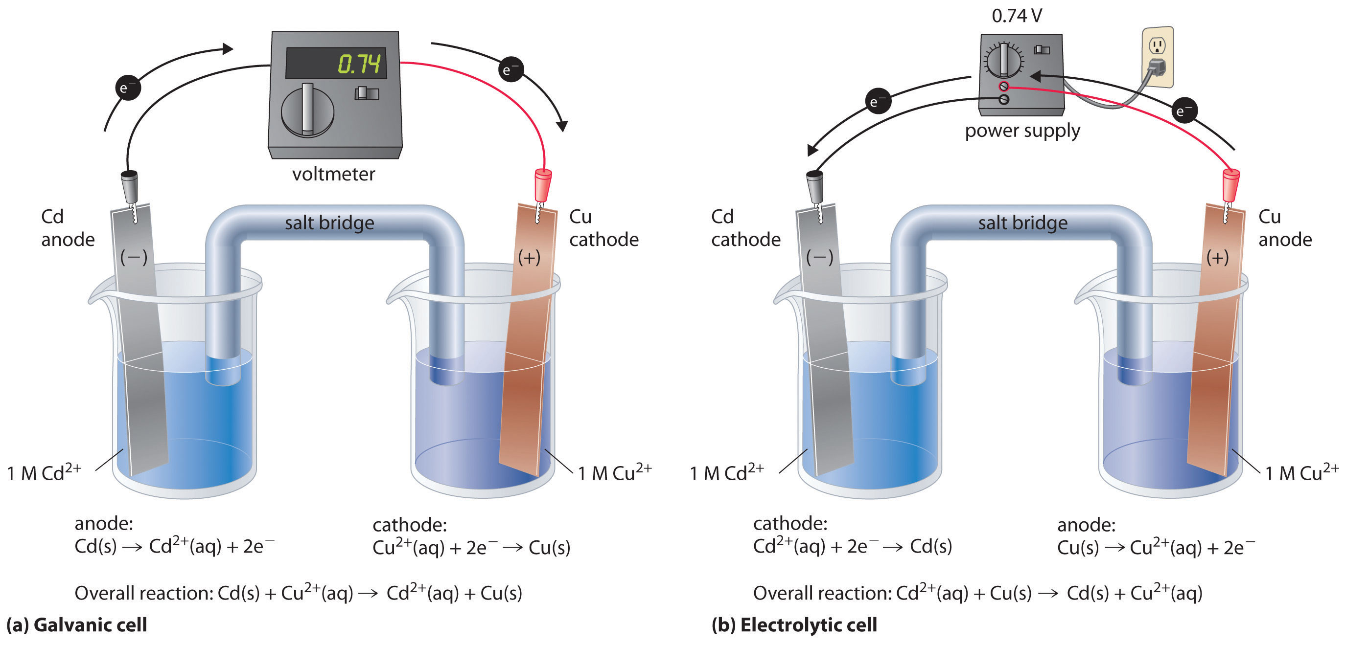
If we construct an electrochemical cell in which one electrode is copper metal immersed in a 1 M Cu2+ solution and the other electrode is cadmium metal immersed in a \(\,1\; M\, Cd^{2+}\) solution and then close the circuit, the potential difference between the two compartments will be 0.74 V. The cadmium electrode will begin to dissolve (Cd is oxidized to Cd2+) and is the anode, while metallic copper will be deposited on the copper electrode (Cu2+ is reduced to Cu), which is the cathode (Figure \(\PageIndex{1a}\)).

Figure \(\PageIndex{1}\): An Applied Voltage Can Reverse the Flow of Electrons in a Galvanic Cd/Cu Cell. (a) When compartments that contain a Cd electrode immersed in 1 M Cd2+(aq) and a Cu electrode immersed in 1 M Cu2+(aq) are connected to create a galvanic cell, Cd(s) is spontaneously oxidized to Cd2+(aq) at the anode, and Cu2+(aq) is spontaneously reduced to Cu(s) at the cathode. The potential of the galvanic cell is 0.74 V. (b) Applying an external potential greater than 0.74 V in the reverse direction forces electrons to flow from the Cu electrode [which is now the anode, at which metallic Cu(s) is oxidized to Cu2+(aq)] and into the Cd electrode [which is now the cathode, at which Cd2+(aq) is reduced to Cd(s)]. The anode in an electrolytic cell is positive because electrons are flowing from it, whereas the cathode is negative because electrons are flowing into it.
The overall reaction is as follows:
\[ \ce{Cd (s) + Cu^{2+} (aq) \rightarrow Cd^{2+} (aq) + Cu (s)} \label{20.9.1}\]
with \(E°_{cell} = 0.74\; V\)
This reaction is thermodynamically spontaneous as written (ΔG° < 0):
\[ \begin{align} \Delta G^\circ &=-nFE^\circ_\textrm{cell} \label{20.9.2a} \\[5pt] &=-(\textrm{2 mol e}^-)[\mathrm{96,486\;J/(V\cdot mol)}](\mathrm{0.74\;V}) \\[5pt] &=-\textrm{140 kJ (per mole Cd)} \label{20.9.2b} \end{align}\]
In this direction, the system is acting as a galvanic cell.
In an electrolytic cell, an external voltage is applied to drive a nonspontaneous reaction.
The reverse reaction, the reduction of Cd2+ by Cu, is thermodynamically nonspontaneous and will occur only with an input of 140 kJ. We can force the reaction to proceed in the reverse direction by applying an electrical potential greater than 0.74 V from an external power supply. The applied voltage forces electrons through the circuit in the reverse direction, converting a galvanic cell to an electrolytic cell. Thus the copper electrode is now the anode (Cu is oxidized), and the cadmium electrode is now the cathode (Cd2+ is reduced) (Figure \(\PageIndex{1b}\)). The signs of the cathode and the anode have switched to reflect the flow of electrons in the circuit. The half-reactions that occur at the cathode and the anode are as follows:
- cathode:
\[\ce{Cd^{2+}(aq) + 2e^{−} \rightarrow Cd(s)}\label{20.9.3}\]
- anode:
\[\ce{Cu(s) \rightarrow Cu^{2+}(aq) + 2e^{−}} \label{20.9.4}\]
with \(E^°_{anode} = 0.34 \, V \)
- Overall:
\[\ce{Cd^{2+}(aq) + Cu(s) \rightarrow Cd(s) + Cu^{2+}(aq) } \label{20.9.5}\]
with \(E^°_{cell} = −0.74 \: V\)
Because \( E^°_{cell} < 0\), the overall reaction—the reduction of \(Cd^{2+}\) by \(Cu\)—clearly cannot occur spontaneously and proceeds only when sufficient electrical energy is applied. The differences between galvanic and electrolytic cells are summarized in Table \(\PageIndex{1}\).
| Property | Galvanic Cell | Electrolytic Cell |
|---|---|---|
| ΔG | < 0 | > 0 |
| Ecell | > 0 | < 0 |
| Electrode Process | ||
| anode | oxidation | oxidation |
| cathode | reduction | reduction |
| Sign of Electrode | ||
| anode | − | + |
| cathode | + | − |
Electrolytic Reactions
At sufficiently high temperatures, ionic solids melt to form liquids that conduct electricity extremely well due to the high concentrations of ions. If two inert electrodes are inserted into molten \(NaCl\), for example, and an electrical potential is applied, \(Cl^−\) is oxidized at the anode, and \(Na^+\) is reduced at the cathode. The overall reaction is as follows:
\[\ce{ 2NaCl (l) \rightarrow 2Na(l) + Cl2(g)} \label{20.9.6}\]
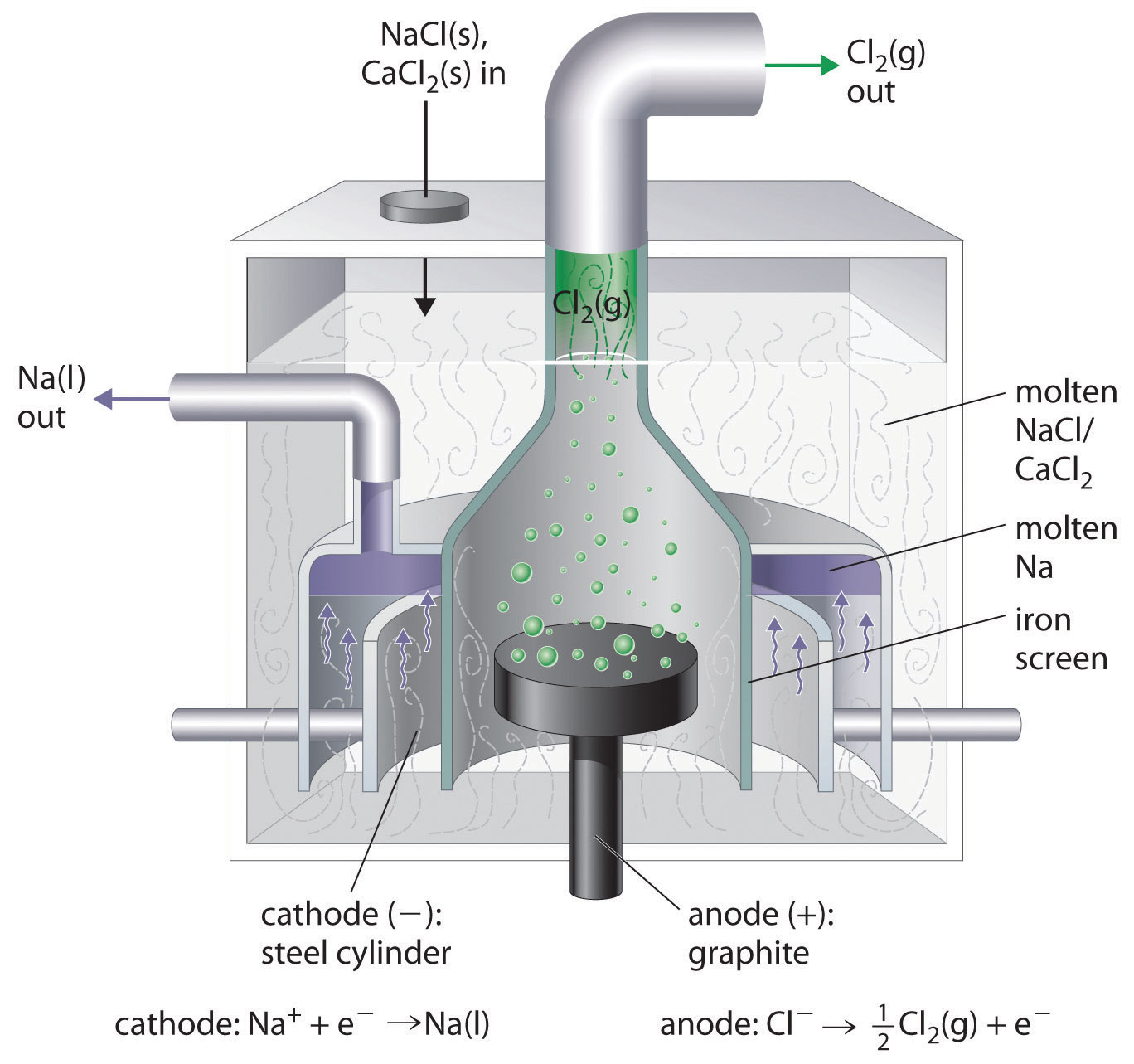
This is the reverse of the formation of NaCl from its elements. The product of the reduction reaction is liquid sodium because the melting point of sodium metal is 97.8°C, well below that of \(NaCl\) (801°C). Approximately 20,000 tons of sodium metal are produced commercially in the United States each year by the electrolysis of molten \(NaCl\) in a Downs cell (Figure \(\PageIndex{2}\)). In this specialized cell, \(CaCl_2\) (melting point = 772°C) is first added to the \(NaCl\) to lower the melting point of the mixture to about 600°C, thereby lowering operating costs.

Figure \(\PageIndex{2}\): A Downs Cell for the Electrolysis of Molten NaCl. The electrolysis of a molten mixture of NaCl and CaCl2 results in the formation of elemental sodium and chlorine gas. Because sodium is a liquid under these conditions and liquid sodium is less dense than molten sodium chloride, the sodium floats to the top of the melt and is collected in concentric capped iron cylinders surrounding the cathode. Gaseous chlorine collects in the inverted cone over the anode. An iron screen separating the cathode and anode compartments ensures that the molten sodium and gaseous chlorine do not come into contact.
Similarly, in the Hall–Heroult process used to produce aluminum commercially, a molten mixture of about 5% aluminum oxide (Al2O3; melting point = 2054°C) and 95% cryolite (Na3AlF6; melting point = 1012°C) is electrolyzed at about 1000°C, producing molten aluminum at the cathode and CO2 gas at the carbon anode. The overall reaction is as follows:
\[2Al_2O_{3(l)} + 3C_{(s)} \rightarrow 4Al_{(l)} + 3CO_{2(g)} \label{20.9.7}\]
Oxide ions react with oxidized carbon at the anode, producing CO2(g).
There are two important points to make about these two commercial processes and about the electrolysis of molten salts in general.
- The electrode potentials for molten salts are likely to be very different from the standard cell potentials listed in Table P2, which are compiled for the reduction of the hydrated ions in aqueous solutions under standard conditions.
- Using a mixed salt system means there is a possibility of competition between different electrolytic reactions. When a mixture of NaCl and CaCl2 is electrolyzed, Cl− is oxidized because it is the only anion present, but either Na+ or Ca2+ can be reduced. Conversely, in the Hall–Heroult process, only one cation is present that can be reduced (Al3+), but there are three species that can be oxidized: C, O2−, and F−.
In the Hall–Heroult process, C is oxidized instead of O2− or F− because oxygen and fluorine are more electronegative than carbon, which means that C is a weaker oxidant than either O2 or F2. Similarly, in the Downs cell, we might expect electrolysis of a NaCl/CaCl2 mixture to produce calcium rather than sodium because Na is slightly less electronegative than Ca (χ = 0.93 versus 1.00, respectively), making Na easier to oxidize and, conversely, Na+ more difficult to reduce. In fact, the reduction of Na+ to Na is the observed reaction. In cases where the electronegativities of two species are similar, other factors, such as the formation of complex ions, become important and may determine the outcome.
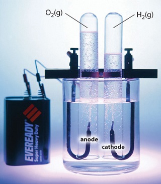
Electrolysis can also be used to drive the thermodynamically nonspontaneous decomposition of water into its constituent elements: H2 and O2. However, because pure water is a very poor electrical conductor, a small amount of an ionic solute (such as H2SO4 or Na2SO4) must first be added to increase its electrical conductivity. Inserting inert electrodes into the solution and applying a voltage between them will result in the rapid evolution of bubbles of H2 and O2 (Figure \(\PageIndex{3}\)).

Figure \(\PageIndex{3}\): The Electrolysis of Water. Applying an external potential of about 1.7–1.9 V to two inert electrodes immersed in an aqueous solution of an electrolyte such as H2SO4 or Na2SO4 drives the thermodynamically nonspontaneous decomposition of water into H2 at the cathode and O2 at the anode.
The reactions that occur are as follows:
- cathode: \[2H^+_{(aq)} + 2e^− \rightarrow H_{2(g)} \;\;\; E^°_{cathode} = 0 V \label{20.9.8}\]
- anode: \[2H_2O_{(l)} → O_{2(g)} + 4H+_{(aq)} + 4e^−\;\;\; E^°_{anode} = 1.23\; V \label{20.9.9}\]
- overall: \[2H_2O_{(l)} → O_{2(g)} + 2H_{2(g)}\;\;\; E^°_{cell} = −1.23 \;V \label{20.9.10}\]
For a system that contains an electrolyte such as Na2SO4, which has a negligible effect on the ionization equilibrium of liquid water, the pH of the solution will be 7.00 and [H+] = [OH−] = 1.0 × 10⁻⁷. Assuming that \(P_\mathrm{O_2}\) = \(P_\mathrm{H_2}\) = 1 atm, we can use the standard potentials to calculate E for the overall reaction:
Thus Ecell is −1.23 V, which is the value of E°cell if the reaction is carried out in the presence of 1 M H+ rather than at pH 7.0.
In practice, a voltage about 0.4–0.6 V greater than the calculated value is needed to electrolyze water. This added voltage, called an overvoltage, represents the additional driving force required to overcome barriers such as the large activation energy for the formation of a gas at a metal surface. Overvoltages are needed in all electrolytic processes, which explain why, for example, approximately 14 V must be applied to recharge the 12 V battery in your car.
In general, any metal that does not react readily with water to produce hydrogen can be produced by the electrolytic reduction of an aqueous solution that contains the metal cation. The p-block metals and most of the transition metals are in this category, but metals in high oxidation states, which form oxoanions, cannot be reduced to the metal by simple electrolysis. Active metals, such as aluminum and those of groups 1 and 2, react so readily with water that they can be prepared only by the electrolysis of molten salts. Similarly, any nonmetallic element that does not readily oxidize water to O2 can be prepared by the electrolytic oxidation of an aqueous solution that contains an appropriate anion. In practice, among the nonmetals, only F2 cannot be prepared using this method. Oxoanions of nonmetals in their highest oxidation states, such as NO3−, SO42−, PO43−, are usually difficult to reduce electrochemically and usually behave like spectator ions that remain in solution during electrolysis.
In general, any metal that does not react readily with water to produce hydrogen can be produced by the electrolytic reduction of an aqueous solution that contains the metal cation.
Electroplating
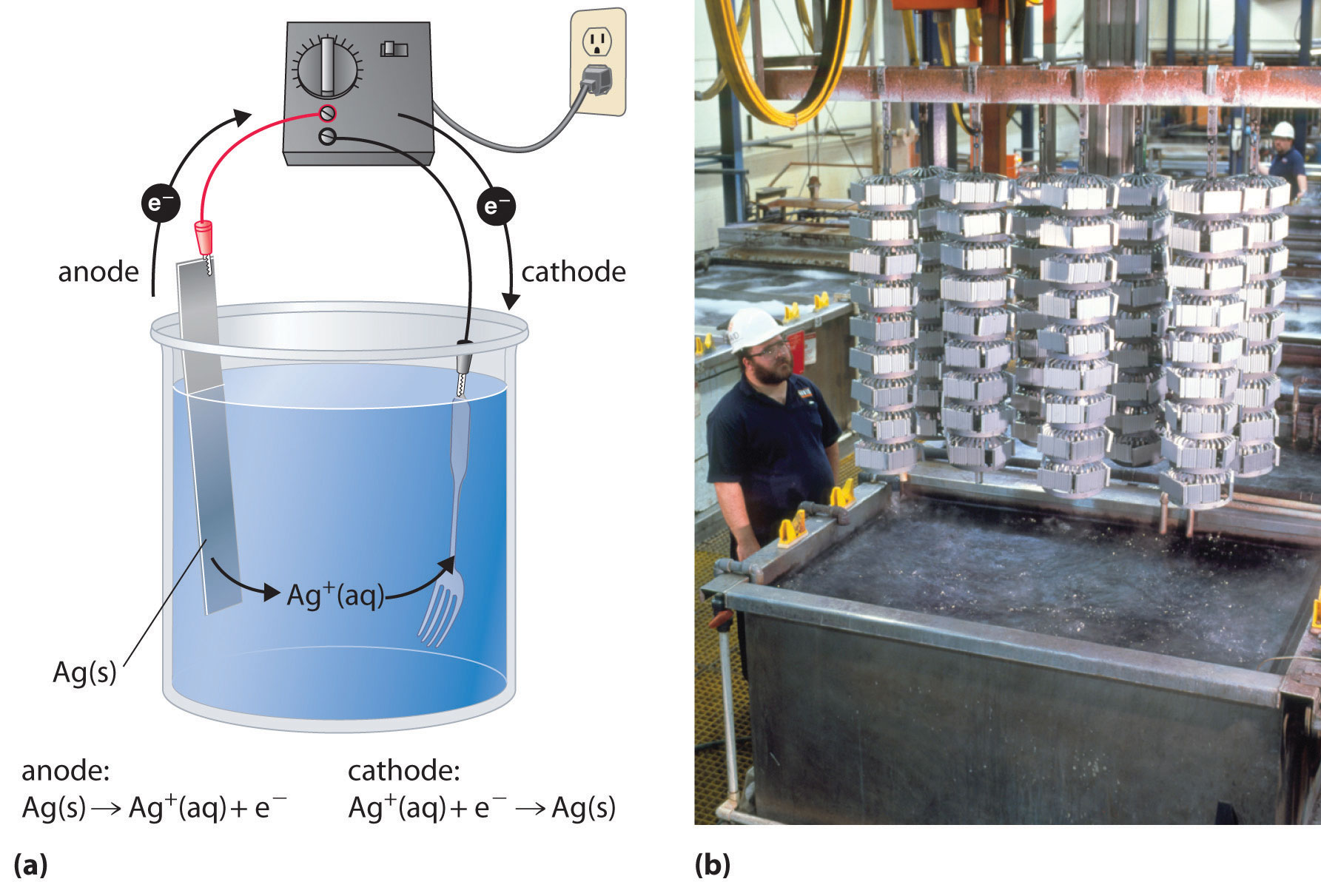
In a process called electroplating, a layer of a second metal is deposited on the metal electrode that acts as the cathode during electrolysis. Electroplating is used to enhance the appearance of metal objects and protect them from corrosion. Examples of electroplating include the chromium layer found on many bathroom fixtures or (in earlier days) on the bumpers and hubcaps of cars, as well as the thin layer of precious metal that coats silver-plated dinnerware or jewelry. In all cases, the basic concept is the same. A schematic view of an apparatus for electroplating silverware and a photograph of a commercial electroplating cell are shown in Figure \(\PageIndex{4}\).

Figure \(\PageIndex{3}\): Electroplating. (a) Electroplating uses an electrolytic cell in which the object to be plated, such as a fork, is immersed in a solution of the metal to be deposited. The object being plated acts as the cathode, on which the desired metal is deposited in a thin layer, while the anode usually consists of the metal that is being deposited (in this case, silver) that maintains the solution concentration as it dissolves. (b) In this commercial electroplating apparatus, a large number of objects can be plated simultaneously by lowering the rack into the Ag+ solution and applying the correct potential.
The half-reactions in electroplating a fork, for example, with silver are as follows:
- cathode (fork): \[Ag^+_{(aq)} + e− \rightarrow Ag_{(s)}\;\;\; E°_{cathode} = 0.80 V\label{20.9.12}\]
- anode (silver bar): \[Ag_{(s)} \rightarrow Ag^+_{(aq)}\;\;\; E°_{anode} = 0.80 V \label{20.9.13}\]
The overall reaction is the transfer of silver metal from one electrode (a silver bar acting as the anode) to another (a fork acting as the cathode). Because E°cell = 0 V, it takes only a small applied voltage to drive the electroplating process. In practice, various other substances may be added to the plating solution to control its electrical conductivity and regulate the concentration of free metal ions, thus ensuring a smooth, even coating.
Summary
In electrolysis, an external voltage is applied to drive a nonspontaneous reaction. The quantity of material oxidized or reduced can be calculated from the stoichiometry of the reaction and the amount of charge transferred. Relationship of charge, current and time:
\[ C = A \times t \nonumber\]
In electrolysis, an external voltage is applied to drive a nonspontaneous reaction. Electrolysis can also be used to produce H2 and O2 from water. In practice, an additional voltage, called an overvoltage, must be applied to overcome factors such as a large activation energy and a junction potential. Electroplating is the process by which a second metal is deposited on a metal surface, thereby enhancing an object’s appearance or providing protection from corrosion. The amount of material consumed or produced in a reaction can be calculated from the stoichiometry of an electrolysis reaction, the amount of current passed, and the duration of the electrolytic reaction.

