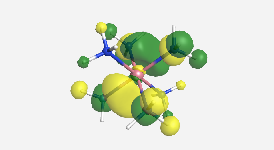
Ligand Field Theory (LFT) can be considered an extension of Crystal Field Theory such that all levels of covalent interactions can be incorporated into the model. LFT describes the bonding, orbital arrangement, and other characteristics of coordination complexes. It represents an application of molecular orbital theory to transition metal complexes. A transition metal has nine valence atomic orbitals: five nd, one (n+1)s, and three (n+1)p orbitals. These orbitals are of appropriate energy to form bonding interaction with ligands. The LFT analysis is highly dependent on the geometry of the complex, but will begin by examining octahedral complexes.
Treatment of the bonding in LFT is generally done using molecular orbital theory. A qualitative approach using generator functions and LGOs can be applied to these compounds just as we did previously. For the purpose of this discussion, we will consider the octahedral complex ion [Co(NH3)6]3+. There are several assumptions that we must make in this approach.
- The 4s, 4p and 3d orbitals are of the correct energy to interact with the nitrogen donor atoms of the NH3 ligands.
- As the NH3 ligands are L-type ligands and will not participate in any π-bonding with the cobalt, we can treat the nitrogen atoms as though they were hydrogen atoms. This means our MO diagram will not account for any N-H bonding. As there are 18 N-H bonds in the complex, it certainly simplifies matters by choosing to ignore this.
Step 1 - Drawing the structure and determining the hybridization of the central atom
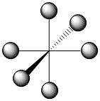
The geometry of the complex has already been specified and the structure of the complex is depicted below (Figure \(\PageIndex{1}\)).
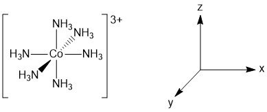
Figure \(\PageIndex{1}\). Structure and assigned axes for [Co(NH3)6]3+.
Exercise \(\PageIndex{1}\)
Using rules for VSEPR, what orbitals need to be used for hybridization of the central cobalt atom? Be as specific as possible about the orbitals.
- Answer
-
The cobalt would be treated as AX6E0 and so would be sp3d2 hybridized.
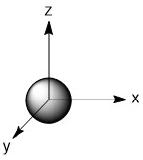
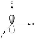
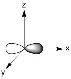
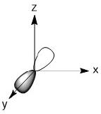
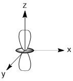
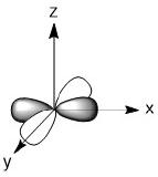
The orbitals involved would be the 4s, 4p and two of the 3d orbitals. For the 3d orbitals, we can decide which ones to involve based on the assigned axes. As we are making σ-bonds, the orbitals involved must be pointing at the incoming ligands. In this geometry that means we much use the dz2 and dx2-y2 orbitals.
Step 2 - Determine the point group of the complex and assign the generator functions
The molecule is octahedral and so the point group is Oh. The Oh character table is rather robust and so only the abbreviated version will appear here.
| Oh |
Orbitals |
| A1g |
s |
| A2g |
|
| Eg |
dz2, dx2-y2 |
| T1g |
|
| T2g |
dxy, dyz, dxz |
| A1u |
|
| A2u |
|
| Eu |
|
| T1u |
px. py, pz |
| T2u |
|
Exercise \(\PageIndex{2}\)
What are the symmetry labels for the cobalt orbitals used to make [Co(NH3)6]3+?.
- Answer
-
s - a1g
px - t1u
py - t1u
pz - t1u
dz2 - eg
dx2-y2 - eg
Step 3 - Making the LGOs
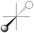
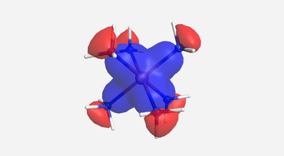
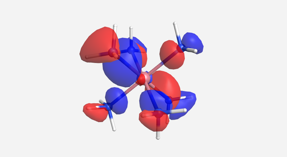
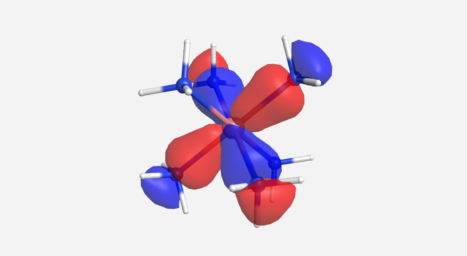
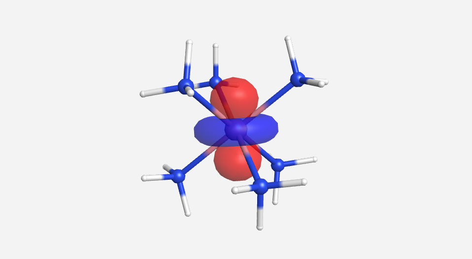
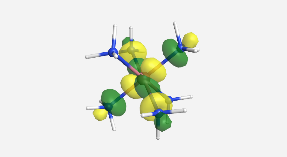
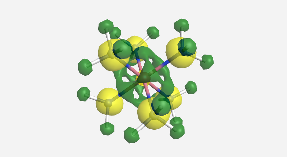
As we have done previously, we will consider all of the potential interactions between the metal orbitals and ligand orbitals using a pictorial method. Based on the axes assigned above, the matching LGOs can be drawn as shown (Figure \(\PageIndex{2}\)).
Figure \(\PageIndex{2}\). LGOs [Co(NH3)6]3+.
Step 4 - Constructing the MO diagram
Previously when we were building MO diagrams we would start by looking at the orbital energies. In this case, doing this is a little more complicated. One complication is that the ligand is NH3 and so we can not just use the orbital energy for nitrogen. Another complication is that the orbital energies for transition metals in various valence states are not as readily available. However, we can make some reasonable approximations. From WebMO, the orbital energies for Co(III) are 3d (-12.12 eV), 4s (-8.10 eV), and 4p (-5.290 eV). The lone pair in NH3 would be the HOMO and from WebMO the energy of this orbital was calculated to be -13.702 eV. The general trend here is that the ligand orbitals are lower in energy than the metal orbitals. Once again we match the symmetry labels and if there is a match on the metal and the LGOs, we make bonding and antibonding orbitals. The t2g orbitals on the metal do not have a match among the LGOs and so they will make non-bonding orbitals that do not change in energy much from the original metal d-orbitals. The rest of the metal orbitals have a match with the LGOs and so we get the diagram below (Figure \(\PageIndex{3}\)).
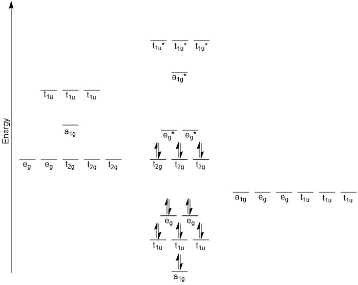
Figure \(\PageIndex{3}\). MO diagram for [Co(NH3)6]3+.
This diagram likely raises a number of questions. One likely question would be the ordering of the bonding MOs. The eg orbitals on the cobalt are the lowest energy, and yet they make the highest energy bonding MOs. Recall from our previous discussion that d-orbitals are not terribly good at forming bonding interactions. The s- and p-orbitals are much better at interacting with the incoming ligands and as such, give rise to lower energy bonding MOs. The a1g orbital is based on the 4s orbital of cobalt which is lower in energy than the 4p orbitals which are t1u. Somewhat similar logic can be applied to the antibonding orbitals. Since the eg orbitals are not very good at forming bonding interactions, their antibonding interactions (eg*) will not be quite as high in energy. The ordering of the a1g* and t1u* orbitals is a bit more difficult to rationalize. However, when considering the electron configuration of a cobalt atom ([Ar] 4s2 3d7), the 4p orbitals are unoccupied. In fact, it may have seemed a bit odd to even consider these orbitals in the hybridization. They are certainly higher in energy and as the t1u* orbitals are more localized on the cobalt, this could cause them to be higher in energy than the a1g* orbital.
Another subtle point is that the d-orbital splitting that was previously discussed is found in this diagram. The MOs are labeled as t2g and eg*. The eg* is slightly different than what we saw in the discussion on crystal field theory. However, these orbitals are closer in energy to the metal d-orbitals and as such are mostly metal d-orbital in character. It is common practice to refer to the t2g and eg* orbitals show in this diagram as the metal d-orbitals but realize there is antibonding character to the eg* orbitals. In addition, this compound is drawn as being Low Spin, with the t2g completely occupied and the eg* unoccupied. Just building the MO diagram there is no way to make that distinction. Looking at the spectrochemical series we see that NH3 is towards the strong field end of the series so a Low Spin configuration is not unreasonable.
Why did we choose NH3?
The choice of NH3 might seem a bit odd at first. Certainly a halide even with three lone pair would have been easier to deal with than NH3. The choice of NH3 was not by chance. The NH3 ligand is purely σ-donating to the cobalt through the lone pair on the nitrogen atom. There are no other lone pair that could be donated to the cobalt to form and kind of π-bonding interaction. Although you may not think of halides as making π-bonds, the lone pair on the halides are capable of interacting in a π-bonding manner with an atom capable of accepting electrons. And it just so happens that the t2g orbitals of a transition metal are of the proper symmetry and energy to interact with ligands capable of donating electrons to give a π-bonding interaction. While we would still draw a single bond (M-Cl) and not a double bond (M=Cl), we should appreciate that there is possibly some π-bonding interaction occurring in a M-Cl bond. In fact, all of the weak field ligands are capable of this sort of interaction to some extent.
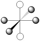
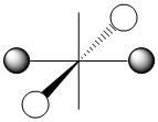
An explanation for strong field ligands is also based on π-bonding arguments. However, in the case of strong field ligands, it is the metal that is providing the electrons in the π-bonding interaction. This interaction is a bit tougher to deal with. Unlike say the halide ligands, we never draw lone pair on metals. This means it is not always readily apparent that there are electrons on the metal available for π-bonding. However, as long as the metal does not have a d0 configuration, we can consider that there are electrons in the t2g orbitals that could be used for π-bonding. Even harder to visualize is how is the ligand going to be accepting these electrons. As we saw for weak field ligands, the key is that the ligand must have an orbital of the right symmetry and energy to be able to interact with a metal t2g orbital. These orbitals are not readily apparent for many ligands. Consider the CO ligand which is called a carbonyl ligand (similar to an organic carbonyl, R2C=O but there are no groups on the carbon atom and so we draw a C≡O). The π-bonding interaction between the carbonyl and the metal involves the π* orbital of CO Figure \(\PageIndex{4}\). Consider first the CO portion depicted. The orbitals are not drawn along the C-O bond axis. This tells us that we are dealing with some type of π-orbital. In the top half of the picture, the orbital is blue on the carbon atom and white on the oxygen atom. And these lobes point away from each other. The combination of the direction and the sign change indicate that this is a π* orbital. In addition (although it is a bit subtle in this picture), the lobes on the carbon atom are larger than the lobes on the oxygen atom. Antibonding orbitals are more localized on the LEAST electronegative atom where as bonding orbitals are localized on the more electronegative atom. This π* orbital of CO has the right symmetry and energy to give a boding interaction with a metal d-orbital. But way, we said this was a π* orbital. It is...with respect to the carbon-oxygen bond. However, the interaction is bonding (as noted by the interaction of lobes with the same sign) with respect to the metal-carbon bond. In general, strong field ligands will share this ability to act as π-acceptors.
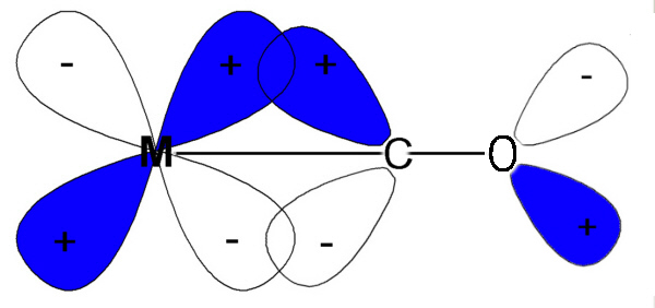
Figure \(\PageIndex{4}\). π interaction between a metal and a carbonyl ligand.
How does this impact our diagram for the metal d-orbitals? In both cases we consider the ligands to be interacting with the t2g orbitals of the metal. In the case of a weak field ligand, the filled orbitals of the π-donating ligand are at a lower energy than the t2g orbitals. The ligand orbitals and the t2g orbitals interact to give π-bonding and π-antibonding orbitals. The π-antibonding orbitals will be more localized on the metal and they will get pushed up in energy relative to the starting t2g orbitals. This will make them closer in energy to the eg orbitals and therefore decrease Δo. With strong field ligands, the metal t2g orbitals are lower in energy than the π-accepting orbitals of the ligands. These orbitals interact to give π-bonding and π-antibonding (with respect to the M-L) orbitals. The π-bonding orbital will go down in energy and be more metal in character. The moves it further away from the eg orbitals and thus increases Δo. These interactions are illustrated below Figure \(\PageIndex{5}\)).
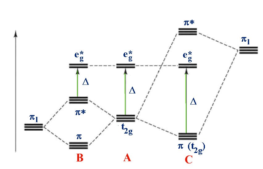
Figure \(\PageIndex{5}\). π interactions between a metal and its ligands (B: [M(II)I6]4-; A: [M(II)(H2O)6]2+; C: [M(II)(CN)6]4-).
Contributors and Attributions


