
Structure and Properties of 3D Printed Metals
- Page ID
- 418924
\( \newcommand{\vecs}[1]{\overset { \scriptstyle \rightharpoonup} {\mathbf{#1}} } \)
\( \newcommand{\vecd}[1]{\overset{-\!-\!\rightharpoonup}{\vphantom{a}\smash {#1}}} \)
\( \newcommand{\dsum}{\displaystyle\sum\limits} \)
\( \newcommand{\dint}{\displaystyle\int\limits} \)
\( \newcommand{\dlim}{\displaystyle\lim\limits} \)
\( \newcommand{\id}{\mathrm{id}}\) \( \newcommand{\Span}{\mathrm{span}}\)
( \newcommand{\kernel}{\mathrm{null}\,}\) \( \newcommand{\range}{\mathrm{range}\,}\)
\( \newcommand{\RealPart}{\mathrm{Re}}\) \( \newcommand{\ImaginaryPart}{\mathrm{Im}}\)
\( \newcommand{\Argument}{\mathrm{Arg}}\) \( \newcommand{\norm}[1]{\| #1 \|}\)
\( \newcommand{\inner}[2]{\langle #1, #2 \rangle}\)
\( \newcommand{\Span}{\mathrm{span}}\)
\( \newcommand{\id}{\mathrm{id}}\)
\( \newcommand{\Span}{\mathrm{span}}\)
\( \newcommand{\kernel}{\mathrm{null}\,}\)
\( \newcommand{\range}{\mathrm{range}\,}\)
\( \newcommand{\RealPart}{\mathrm{Re}}\)
\( \newcommand{\ImaginaryPart}{\mathrm{Im}}\)
\( \newcommand{\Argument}{\mathrm{Arg}}\)
\( \newcommand{\norm}[1]{\| #1 \|}\)
\( \newcommand{\inner}[2]{\langle #1, #2 \rangle}\)
\( \newcommand{\Span}{\mathrm{span}}\) \( \newcommand{\AA}{\unicode[.8,0]{x212B}}\)
\( \newcommand{\vectorA}[1]{\vec{#1}} % arrow\)
\( \newcommand{\vectorAt}[1]{\vec{\text{#1}}} % arrow\)
\( \newcommand{\vectorB}[1]{\overset { \scriptstyle \rightharpoonup} {\mathbf{#1}} } \)
\( \newcommand{\vectorC}[1]{\textbf{#1}} \)
\( \newcommand{\vectorD}[1]{\overrightarrow{#1}} \)
\( \newcommand{\vectorDt}[1]{\overrightarrow{\text{#1}}} \)
\( \newcommand{\vectE}[1]{\overset{-\!-\!\rightharpoonup}{\vphantom{a}\smash{\mathbf {#1}}}} \)
\( \newcommand{\vecs}[1]{\overset { \scriptstyle \rightharpoonup} {\mathbf{#1}} } \)
\(\newcommand{\longvect}{\overrightarrow}\)
\( \newcommand{\vecd}[1]{\overset{-\!-\!\rightharpoonup}{\vphantom{a}\smash {#1}}} \)
\(\newcommand{\avec}{\mathbf a}\) \(\newcommand{\bvec}{\mathbf b}\) \(\newcommand{\cvec}{\mathbf c}\) \(\newcommand{\dvec}{\mathbf d}\) \(\newcommand{\dtil}{\widetilde{\mathbf d}}\) \(\newcommand{\evec}{\mathbf e}\) \(\newcommand{\fvec}{\mathbf f}\) \(\newcommand{\nvec}{\mathbf n}\) \(\newcommand{\pvec}{\mathbf p}\) \(\newcommand{\qvec}{\mathbf q}\) \(\newcommand{\svec}{\mathbf s}\) \(\newcommand{\tvec}{\mathbf t}\) \(\newcommand{\uvec}{\mathbf u}\) \(\newcommand{\vvec}{\mathbf v}\) \(\newcommand{\wvec}{\mathbf w}\) \(\newcommand{\xvec}{\mathbf x}\) \(\newcommand{\yvec}{\mathbf y}\) \(\newcommand{\zvec}{\mathbf z}\) \(\newcommand{\rvec}{\mathbf r}\) \(\newcommand{\mvec}{\mathbf m}\) \(\newcommand{\zerovec}{\mathbf 0}\) \(\newcommand{\onevec}{\mathbf 1}\) \(\newcommand{\real}{\mathbb R}\) \(\newcommand{\twovec}[2]{\left[\begin{array}{r}#1 \\ #2 \end{array}\right]}\) \(\newcommand{\ctwovec}[2]{\left[\begin{array}{c}#1 \\ #2 \end{array}\right]}\) \(\newcommand{\threevec}[3]{\left[\begin{array}{r}#1 \\ #2 \\ #3 \end{array}\right]}\) \(\newcommand{\cthreevec}[3]{\left[\begin{array}{c}#1 \\ #2 \\ #3 \end{array}\right]}\) \(\newcommand{\fourvec}[4]{\left[\begin{array}{r}#1 \\ #2 \\ #3 \\ #4 \end{array}\right]}\) \(\newcommand{\cfourvec}[4]{\left[\begin{array}{c}#1 \\ #2 \\ #3 \\ #4 \end{array}\right]}\) \(\newcommand{\fivevec}[5]{\left[\begin{array}{r}#1 \\ #2 \\ #3 \\ #4 \\ #5 \\ \end{array}\right]}\) \(\newcommand{\cfivevec}[5]{\left[\begin{array}{c}#1 \\ #2 \\ #3 \\ #4 \\ #5 \\ \end{array}\right]}\) \(\newcommand{\mattwo}[4]{\left[\begin{array}{rr}#1 \amp #2 \\ #3 \amp #4 \\ \end{array}\right]}\) \(\newcommand{\laspan}[1]{\text{Span}\{#1\}}\) \(\newcommand{\bcal}{\cal B}\) \(\newcommand{\ccal}{\cal C}\) \(\newcommand{\scal}{\cal S}\) \(\newcommand{\wcal}{\cal W}\) \(\newcommand{\ecal}{\cal E}\) \(\newcommand{\coords}[2]{\left\{#1\right\}_{#2}}\) \(\newcommand{\gray}[1]{\color{gray}{#1}}\) \(\newcommand{\lgray}[1]{\color{lightgray}{#1}}\) \(\newcommand{\rank}{\operatorname{rank}}\) \(\newcommand{\row}{\text{Row}}\) \(\newcommand{\col}{\text{Col}}\) \(\renewcommand{\row}{\text{Row}}\) \(\newcommand{\nul}{\text{Nul}}\) \(\newcommand{\var}{\text{Var}}\) \(\newcommand{\corr}{\text{corr}}\) \(\newcommand{\len}[1]{\left|#1\right|}\) \(\newcommand{\bbar}{\overline{\bvec}}\) \(\newcommand{\bhat}{\widehat{\bvec}}\) \(\newcommand{\bperp}{\bvec^\perp}\) \(\newcommand{\xhat}{\widehat{\xvec}}\) \(\newcommand{\vhat}{\widehat{\vvec}}\) \(\newcommand{\uhat}{\widehat{\uvec}}\) \(\newcommand{\what}{\widehat{\wvec}}\) \(\newcommand{\Sighat}{\widehat{\Sigma}}\) \(\newcommand{\lt}{<}\) \(\newcommand{\gt}{>}\) \(\newcommand{\amp}{&}\) \(\definecolor{fillinmathshade}{gray}{0.9}\)-
I. B. Electrons play the key role for atoms to bond with other atoms.
-
II. G. Metallic bonding arises in many solids and fundamentally involves the sharing of valence electrons among many positively charged “cores” over extended distances.
-
III. H. Many solid-state, extended systems exist, and geometric structures play an important role in understanding the properties of these systems.
As manufacturing becomes increasingly complex in the modern world, so have the ways in which metals are constructed. Manufacturing of metal parts has been almost mastered by the industrial sector, but traditional methods, such as casting and forging1, have their drawbacks.
A lot of the properties that we associate with metals, such as their malleability and capacity to conduct electricity, can be explained by both their structure and how the metal atoms bond with each other. Metal atoms can be imagined as a sphere. There are both pure metals and alloys (metals that contain two or more different ions). These atoms are packed together in a few different arrangements. One of them is closest packing, in which the spheres are packed in layers, either hexagonal or cubic, that use the most space. There is also simple cubic packing (atoms simply stacked) and body-centered cubic packing.2 Different metals exhibit different types of bonding, which can explain why some are more malleable or ductile than others. We can also use calculations to calculate a theoretical density based on the structure.
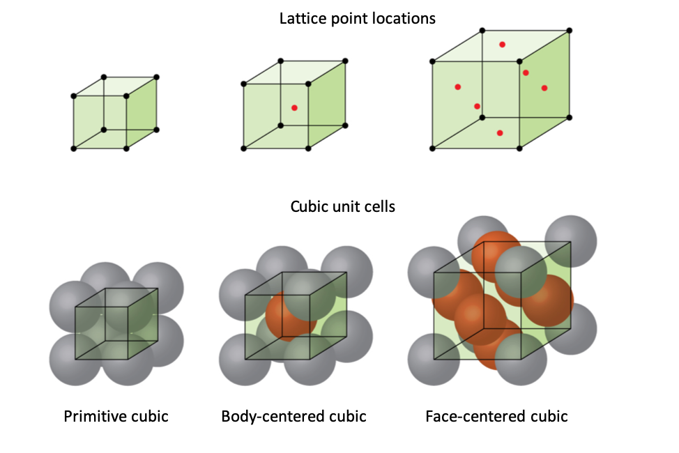
Figure 1. Differerent Packing Structures3. Primitive cubic is another term for simple cubic packing, and face-centered cubic is another term for closest packing.
The bonding of metals is different from typical covalent or ionic bonding. Between the metal nuclei exists a “sea of electrons” in which these electrons are not necessarily attracted to only one atom, but rather free flowing between them.2 This makes the bonding both strong and non-directional. These floating electrons also explain the great conductivity of most metals, as the flow of electrons is easily permitted in this sea.
Figure 2. Sea of Electrons2
In Figure 2, what metal(s) might Diagram A be representing of its "sea of electrons"? What about Diagram B?
Solution
We can see that in Diagram A that the nuclei have a +1 charge. Assuming those ions have a full valence shell, the nuclei in Diagram A must be one of the alkali metals. Using the same logic, Diagram B must represent one of the alkaline earth metals.
A more complex explanation would be the band model, which explains that the valence electrons in this sea create different molecular orbitals (MOs), some occupied and some unoccupied, but all close in energy.2 Electrons are free to move between the different orbitals as there is only a small difference between the MOs.
Figure 3. Band Model2
Using either the "sea of electrons" model or the band model, explain why malleability is property of metals.
Solution
Both of these models say that the electrons are not localized to one atom and move freely among the different nuclei. Since the bonds in metals are nondirectional, hammering a metal will only move the nuclei, not break the metal bonding.
The introduction of 3D printed metals was due to a realization in the impracticalities of current methods and their limitations. A lot of the techniques that companies use are variations on a process called powder bed fusion. Metal is ground up into a fine crystalline powder and placed into a chamber isolated from the outside environment. Then, a power source, often a laser, fuses the metal atoms together and onto the desired location.4 Other metal 3D printing techniques exist and are constantly being iterated, such as friction-stir deposition, but powder bed fusion is one of the most prominent techniques, especially for smaller parts or parts where small defects are not detrimental to design.
3D printing metals does come with challenges. It is difficult to create metal alloys as strong as ones that are created by forging, and there is a greater probability of cracks forming.4 For this reason, scientists are researching which metal alloys work best for 3D printing through the powder bed fusion method. One proposed solution to this problem involved implanting nanoparticles between the metal atoms, which improves the strength and quality of the print. Computers can also be used to predict which alloys will work best in prints based on factors such as thermodynamic favorability, similar structure, and abundance.1
A study was done creating Cu-Cr-Zr copper alloys containing Cu2O nano precipitates. In order to create this structure, scientists studied the bonding in the alloy and concluded that high heat must be provided to create a dense structure. With not enough heat/energy, the bonding created would be too poor, and the metal would break apart.1 When the powder is melting, the electrons are easily able to move between MOs and are introduced into their “sea of electrons”. The precision of the laser beams allows the powder to take form into a layer of metal and eventually become a functioning metal “part.” The introduction of the nanoparticles also allows the new metal to keep its solid shape.
A metal 3D printer prints a copper alloy with both interstitial and substitutional atoms. Knowing that copper exhibits cubic closest packing and the radius of the Cu atom is 1.28 Å, calculate the minimum density of the metal (assume the substitutional alloys have the same radius length to that of copper).
Solution
By taking a cross section of the cubic closest packing structure, we can derive the equation using the Pythagorean Theorem based on the fact that d is the length of the unit cell and r is the radius of the atom.
\[d^2 + d^2 = (4r)^2\]
We then isolate the variable d and use it to find the volume of the entire unit cell.
\[2d^2 = 16r^2\]
\[d^2 = 8r^2\]
\[d = r\sqrt{8}\]
\[d = (1.28\ Å) (\sqrt{8}) = 3.62\ Å\]
\[V = d^3 = (3.62\ Å)^3 = 47.5\ Å^3\]
Once we convert Angstroms to moles, we can simply use our density equation by plugging in the molar mass (converted into grams per atom and multiplied by the amount of atoms in the cell) and dividing that by the entire volume of the unit cell found earlier.
\[\left(47.5\ Å^3\right) \left(\frac{1.00\text{x}10^{-8}\ \text{cm}}{1\ Å}\right)^3 = 4.75\text{x}10^{-23}\ \text{cm}^3\]
\[D = \frac{m}{V} = (4\ \text{atoms}) \left(\frac{63.546\ \text{g}}{1\ \text{mol}}\right) \left(\frac{1\ \text{mol}}{6.022\text{x}10^{23}\ \text{atoms}}\right) \left(\frac{1}{4.75\text{x}10^{23}\ \text{cm}^3}\right)\]
\[D = 8.89\ \text{g/cm}^3\]
Metal 3D printers can print many different metals or alloys. It is often very important for the density of printed materials to be known for weight, construction, and stability purposes.4 Although this is a somewhat simplified problem with only one metal, the same principles can be applied to calculate the density of alloys or other metals so that it can be known and used for other calculations. Often, density is an important factor when considering what materials should be used for construction, so the ability to calculate this before a print is beneficial.
Inconel 625 is a “superalloy” with a base of nickel that is used often in 3D printing metals and is known for its high strength and heat resistant properties5. Explain why this is a good choice for a metal to 3D print.
Solution
These two explanations would be the most convincing:
- Nickel exhibits closest cubic packing structure, which reduces possible gaps in the metal and makes it stronger. The space can also be further eliminated with the use of both interstitial and substitutional atoms in the alloy.2
- There is a lot of time eliminated when 3D printing Inconel 625 rather than using traditional methods because the power source, usually a laser beam or electron beam, has a higher energy4 and can melt the metal much quicker than done through traditional manufacturing.4
References
1: Jeyaprakash, N; Kumar, M. Saravana; Yang, Che-Hua. Enhanced Nano-level Mechanical Responses on Additively Manufactured Cu-Cr-Zr Copper Alloy Containing Cu2O Nano Precipitates. Journal of Alloys and Compounds, 2022. 0925-8388. DOI: 10.1016/j.jallcom.2022.167425
2: Zumdahl, S; DeCoste, D. Liquids and Solids. In Chemical Principles, 8th Edition. Cengage Learning, 2016.
3: Crlandis. 61. Types of Unit Cells: Body-Centered Cubic and Face-Centered Cubic (M11Q5). In UW-Madison Chemistry 103/104 Resource Book. Pressbooks, 2016.
4: Patel, P. 3D Printed Metal is Getting Better, Faster, and Stronger. Chemical and Engineering News, 2022. https://cen.acs.org/materials/3-d-pr...better/100/i38 (accessed Nov 10, 2022).
5: Martin, J.H ; Yahata, B.D ; Hundley, J.M; Mayer, J.A; Scaedler, T.A; Pollock, T.M. 3D Printing of High Strength Aluminium Alloys. Nature Portfolio, 2022. 1476-4687 https://www.nature.com/articles/nature23894.