
4.6: Carbon Nanomaterials
- Page ID
- 281587

\( \newcommand{\vecs}[1]{\overset { \scriptstyle \rightharpoonup} {\mathbf{#1}} } \)
\( \newcommand{\vecd}[1]{\overset{-\!-\!\rightharpoonup}{\vphantom{a}\smash {#1}}} \)
\( \newcommand{\id}{\mathrm{id}}\) \( \newcommand{\Span}{\mathrm{span}}\)
( \newcommand{\kernel}{\mathrm{null}\,}\) \( \newcommand{\range}{\mathrm{range}\,}\)
\( \newcommand{\RealPart}{\mathrm{Re}}\) \( \newcommand{\ImaginaryPart}{\mathrm{Im}}\)
\( \newcommand{\Argument}{\mathrm{Arg}}\) \( \newcommand{\norm}[1]{\| #1 \|}\)
\( \newcommand{\inner}[2]{\langle #1, #2 \rangle}\)
\( \newcommand{\Span}{\mathrm{span}}\)
\( \newcommand{\id}{\mathrm{id}}\)
\( \newcommand{\Span}{\mathrm{span}}\)
\( \newcommand{\kernel}{\mathrm{null}\,}\)
\( \newcommand{\range}{\mathrm{range}\,}\)
\( \newcommand{\RealPart}{\mathrm{Re}}\)
\( \newcommand{\ImaginaryPart}{\mathrm{Im}}\)
\( \newcommand{\Argument}{\mathrm{Arg}}\)
\( \newcommand{\norm}[1]{\| #1 \|}\)
\( \newcommand{\inner}[2]{\langle #1, #2 \rangle}\)
\( \newcommand{\Span}{\mathrm{span}}\) \( \newcommand{\AA}{\unicode[.8,0]{x212B}}\)
\( \newcommand{\vectorA}[1]{\vec{#1}} % arrow\)
\( \newcommand{\vectorAt}[1]{\vec{\text{#1}}} % arrow\)
\( \newcommand{\vectorB}[1]{\overset { \scriptstyle \rightharpoonup} {\mathbf{#1}} } \)
\( \newcommand{\vectorC}[1]{\textbf{#1}} \)
\( \newcommand{\vectorD}[1]{\overrightarrow{#1}} \)
\( \newcommand{\vectorDt}[1]{\overrightarrow{\text{#1}}} \)
\( \newcommand{\vectE}[1]{\overset{-\!-\!\rightharpoonup}{\vphantom{a}\smash{\mathbf {#1}}}} \)
\( \newcommand{\vecs}[1]{\overset { \scriptstyle \rightharpoonup} {\mathbf{#1}} } \)
\( \newcommand{\vecd}[1]{\overset{-\!-\!\rightharpoonup}{\vphantom{a}\smash {#1}}} \)
\(\newcommand{\avec}{\mathbf a}\) \(\newcommand{\bvec}{\mathbf b}\) \(\newcommand{\cvec}{\mathbf c}\) \(\newcommand{\dvec}{\mathbf d}\) \(\newcommand{\dtil}{\widetilde{\mathbf d}}\) \(\newcommand{\evec}{\mathbf e}\) \(\newcommand{\fvec}{\mathbf f}\) \(\newcommand{\nvec}{\mathbf n}\) \(\newcommand{\pvec}{\mathbf p}\) \(\newcommand{\qvec}{\mathbf q}\) \(\newcommand{\svec}{\mathbf s}\) \(\newcommand{\tvec}{\mathbf t}\) \(\newcommand{\uvec}{\mathbf u}\) \(\newcommand{\vvec}{\mathbf v}\) \(\newcommand{\wvec}{\mathbf w}\) \(\newcommand{\xvec}{\mathbf x}\) \(\newcommand{\yvec}{\mathbf y}\) \(\newcommand{\zvec}{\mathbf z}\) \(\newcommand{\rvec}{\mathbf r}\) \(\newcommand{\mvec}{\mathbf m}\) \(\newcommand{\zerovec}{\mathbf 0}\) \(\newcommand{\onevec}{\mathbf 1}\) \(\newcommand{\real}{\mathbb R}\) \(\newcommand{\twovec}[2]{\left[\begin{array}{r}#1 \\ #2 \end{array}\right]}\) \(\newcommand{\ctwovec}[2]{\left[\begin{array}{c}#1 \\ #2 \end{array}\right]}\) \(\newcommand{\threevec}[3]{\left[\begin{array}{r}#1 \\ #2 \\ #3 \end{array}\right]}\) \(\newcommand{\cthreevec}[3]{\left[\begin{array}{c}#1 \\ #2 \\ #3 \end{array}\right]}\) \(\newcommand{\fourvec}[4]{\left[\begin{array}{r}#1 \\ #2 \\ #3 \\ #4 \end{array}\right]}\) \(\newcommand{\cfourvec}[4]{\left[\begin{array}{c}#1 \\ #2 \\ #3 \\ #4 \end{array}\right]}\) \(\newcommand{\fivevec}[5]{\left[\begin{array}{r}#1 \\ #2 \\ #3 \\ #4 \\ #5 \\ \end{array}\right]}\) \(\newcommand{\cfivevec}[5]{\left[\begin{array}{c}#1 \\ #2 \\ #3 \\ #4 \\ #5 \\ \end{array}\right]}\) \(\newcommand{\mattwo}[4]{\left[\begin{array}{rr}#1 \amp #2 \\ #3 \amp #4 \\ \end{array}\right]}\) \(\newcommand{\laspan}[1]{\text{Span}\{#1\}}\) \(\newcommand{\bcal}{\cal B}\) \(\newcommand{\ccal}{\cal C}\) \(\newcommand{\scal}{\cal S}\) \(\newcommand{\wcal}{\cal W}\) \(\newcommand{\ecal}{\cal E}\) \(\newcommand{\coords}[2]{\left\{#1\right\}_{#2}}\) \(\newcommand{\gray}[1]{\color{gray}{#1}}\) \(\newcommand{\lgray}[1]{\color{lightgray}{#1}}\) \(\newcommand{\rank}{\operatorname{rank}}\) \(\newcommand{\row}{\text{Row}}\) \(\newcommand{\col}{\text{Col}}\) \(\renewcommand{\row}{\text{Row}}\) \(\newcommand{\nul}{\text{Nul}}\) \(\newcommand{\var}{\text{Var}}\) \(\newcommand{\corr}{\text{corr}}\) \(\newcommand{\len}[1]{\left|#1\right|}\) \(\newcommand{\bbar}{\overline{\bvec}}\) \(\newcommand{\bhat}{\widehat{\bvec}}\) \(\newcommand{\bperp}{\bvec^\perp}\) \(\newcommand{\xhat}{\widehat{\xvec}}\) \(\newcommand{\vhat}{\widehat{\vvec}}\) \(\newcommand{\uhat}{\widehat{\uvec}}\) \(\newcommand{\what}{\widehat{\wvec}}\) \(\newcommand{\Sighat}{\widehat{\Sigma}}\) \(\newcommand{\lt}{<}\) \(\newcommand{\gt}{>}\) \(\newcommand{\amp}{&}\) \(\definecolor{fillinmathshade}{gray}{0.9}\)Nanomaterials: Fullerenes and Nanotubes
Fullerenes
Carbon-60 (C60) is probably the most studied individual type of nanomaterial. The spherical shape of C60 is constructed from twelve pentagons and twenty hexagons and resembles a soccer ball (Figure \(\PageIndex{1}\)a). The next stable higher fullerene is C70 (Figure \(\PageIndex{1}\)b) that is shaped like a rugby or American football. The progression of higher fullerenes continues in the sequence C74, C76, C78, etc. The structural relationship between each involves the addition of six membered rings. Mathematically (and chemically) two principles define the existence of a stable fullerene, i.e., Euler’s theorem and isolated pentagon rule (IPR). Euler’s theorem states that for the closure of each spherical network, n (n ≥ 2) hexagons and 12 pentagons are required while the IPR says no two pentagons may be connected directly with each other as destabilization is caused by two adjacent pentagons.
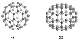
Although fullerenes are composed of sp2 carbons in a similar manner to graphite, fullerenes are soluble in various common organic solvents. Due to their hydrophobic nature, fullerenes are most soluble in CS2 (C60 = 7.9 mg/mL) and toluene (C60 = 2.8 mg/mL). Although fullerenes have a conjugated system, their aromaticity is distinctive from benzene that has all C-C bonds of equal lengths, in fullerenes two distinct classes of bonds exist. The shorter bonds are at the junctions of two hexagons ([6, 6] bonds) and the longer bonds at the junctions of a hexagon and a pentagon ([5,6] bonds). This difference in bonding is responsible for some of the observed reactivity of fullerenes.
Synthesis of fullerenes
The first observation of fullerenes was in molecular beam experiments at Rice University. Subsequent studies demonstrated that C60 it was relatively easy to produce grams of fullerenes. Although the synthesis is relatively straightforward fullerene purification remains a challenge and determines fullerene’s commercial price. The first method of production of measurable quantities of fullerenes used laser vaporization of carbon in an inert atmosphere, but this produced microscopic amounts of fullerenes. Laboratory scales of fullerene are prepared by the vaporization of carbon rods in a helium atmosphere. Commercial production ordinarily employs a simple ac or dc arc. The fullerenes in the black soot collected are extracted in toluene and purified by liquid chromatography. The magenta C60 comes off the column first, followed by the red C70, and other higher fullerenes. Even though the mechanism of a carbon arc differs from that of a resistively heated carbon rod (because it involves a plasma) the He pressure for optimum C60 formation is very similar.
A ratio between the mass of fullerenes and the total mass of carbon soot defines fullerene yield. The yields determined by UV-Vis absorption are approximately 40%, 10-15%, and 15% in laser, electric arc, and solar processes. Interestingly, the laser ablation technique has both the highest yield and the lowest productivity and, therefore, a scale-up to a higher power is costly. Thus, fullerene commercial production is a challenging task. The world's first computer controlled fullerene production plant is now operational at the MER Corporation, who pioneered the first commercial production of fullerene and fullerene products.
Carbon nanotubes
A key breakthrough in carbon nanochemistry came in 1993 with the report of needle-like tubes made exclusively of carbon. This material became known as carbon nanotubes (CNTs). There are several types of nanotubes. The first discovery was of multi walled tubes (MWNTs) resembling many pipes nested within each other. Shortly after MWNTs were discovered single walled nanotubes (SWNTs) were observed. Single walled tubes resemble a single pipe that is potentially capped at each end. The properties of single walled and multi walled tubes are generally the same, although single walled tubes are believed to have superior mechanical strength and thermal and electrical conductivity; it is also more difficult to manufacture them.
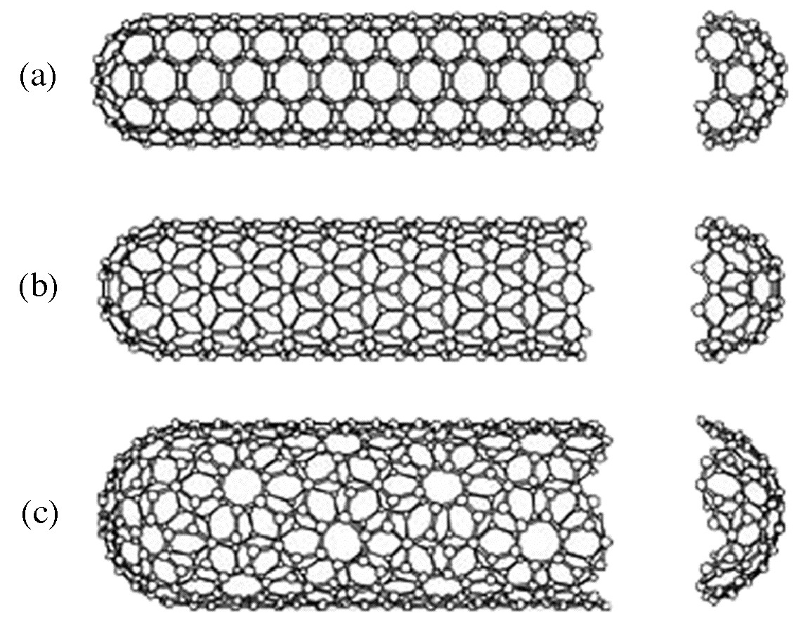
Single walled carbon nanotubes (SWNTs) are by definition fullerene materials. Their structure consists of a graphene sheet rolled into a tube and capped by half a fullerene (Figure \(\PageIndex{6}\)). The carbon atoms in a SWNT, like those in a fullerene, are sp2 hybridized. The structure of a nanotube is analogous to taking this graphene sheet and rolling it into a seamless cylinder. The different types of SWNTs are defined by their diameter and chirality. Most of the presently used single-wall carbon nanotubes have been synthesized by the pulsed laser vaporization method, however, increasingly SWNTs are prepared by vapor liquid solid catalyzed growth.
The physical properties of SWNTs have made them an extremely attractive material for the manufacturing of nano devices. SWNTs have been shown to be stronger than steel as estimates for the Young’s modulus approaches 1 Tpa. Their electrical conductance is comparable to copper with anticipate current densities of up to 1013 A/cm2 and a resistivity as low as 0.34 x 10⁻⁴ Ω.cm at room temperatures. Finally, they have a high thermal conductivity (3000 - 6000 W.m/K).
The electronic properties of a particular SWNT structure are based on its chirality or twist in the structure of the tube which is defined by its n,m value. The values of n and m determine the chirality, or "twist" of the nanotube. The chirality in turn affects the conductance of the nanotube, its density, its lattice structure, and other properties. A SWNT is considered metallic if the value n-m is divisible by three. Otherwise, the nanotube is semi-conducting. The external environment also has an effect on the conductance of a tube, thus molecules such as O2 and NH3 can change the overall conductance of a tube, while the presence of metals have been shown to significantly effect the opto-electronic properties of SWNTs.
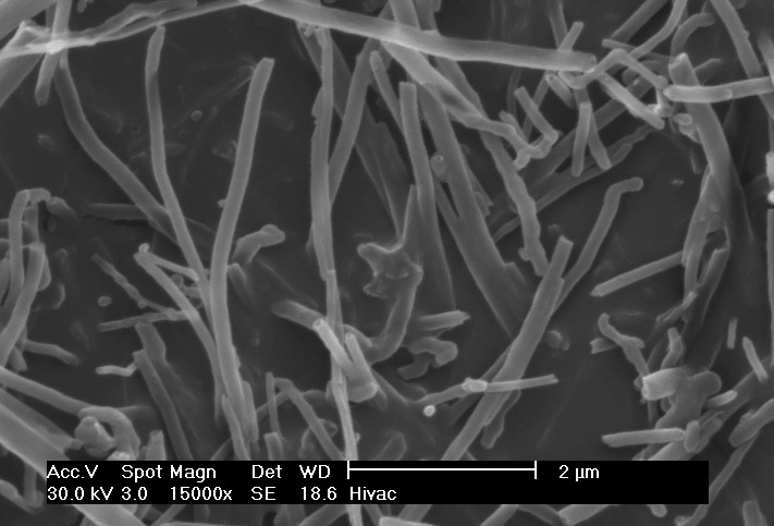
Multi walled carbon nanotubes (MWNTs) range from double walled NTs, through many-walled NTs (Figure \(\PageIndex{7}\)) to carbon nanofibers. Carbon nanofibers are the extreme of multi walled tubes (Figure \(\PageIndex{8}\)) and they are thicker and longer than either SWNTs or MWNTs, having a cross-sectional of ca. 500 Å2 and are between 10 to 100 μm in length. They have been used extensively in the construction of high strength composites.

Synthesis of carbon nanotubes
A range of methodologies have been developed to produce nanotubes in sizeable quantities, including arc discharge, laser ablation, high pressure carbon monoxide (HiPco), and vapor liquid solid (VLS) growth. All these processes take place in vacuum or at low pressure with a process gases, although VLS growth can take place at atmospheric pressure. Large quantities of nanotubes can be synthesized by these methods; advances in catalysis and continuous growth processes are making SWNTs more commercially viable.
Chemical functionalization of carbon nanotubes
The limitation of using carbon nanotubes in any practical applications has been its solubility; for example SWNTs have little to no solubility in most solvent due to the aggregation of the tubes. Aggregation/roping of nanotubes occurs as a result of the high van der Waals binding energy of ca. 500 eV per mm of tube contact. The van der Waals force between the tubes is so great, that it take tremendous energy to pry them apart, making it very to make combination of nanotubes with other materials such as in composite applications. The functionalization of nanotubes, i.e., the attachment of “chemical functional groups” provides the path to overcome these barriers. Functionalization can improve solubility as well as processibility, and has been used to align the properties of nanotubes to those of other materials. The clearest example of this is the ability to solubilize nanotubes in a variety of solvents, including water. It is important when discussing functionalization that a distinction is made between covalent and non-covalent functionalization.
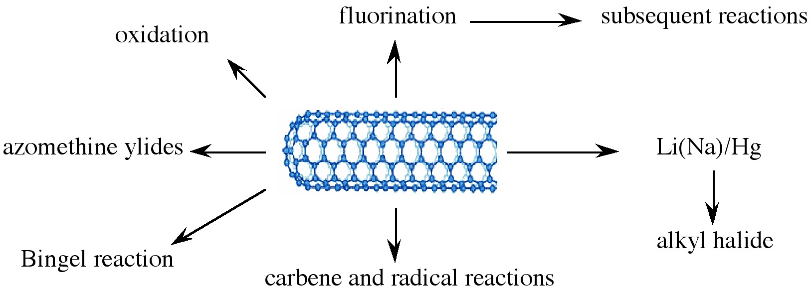
Various applications of nanotubes require different, specific modification to achieve desirable physical and chemical properties of nanotubes. In this regard, covalent functionalization provides a higher degree of fine-tuning the chemistry and physics of SWNTs than non-covalent functionalization. Until now, a variety of methods have been used to achieve the functionalization of nanotubes (Figure \(\PageIndex{9}\)).
Bibliography
- S. M. Bachilo, M. S. Strano, C. Kittrell, R. H. Hauge, R. E. Smalley, and R. B. Weisman, Science, 2002, 298, 2361.
- D. S. Bethune, C. H. Klang, M. S. deVries, G. Gorman, R. Savoy, J. Vazquez, and R. Beyers, Nature, 1993, 363, 605.
- J, J. Brege, C. Gallaway, and A. R. Barron, J. Phys. Chem., C, 2007, 111, 17812.
- C. A. Dyke and J. M. Tour, J. Am. Chem. Soc., 2003, 125, 1156.
- Z. Ge, J. C. Duchamp, T. Cai, H. W. Gibson, and H. C. Dorn, J. Am. Chem. Soc., 2005, 127, 16292.
- L. A. Girifalco, M. Hodak, and R. S. Lee, Phys. Rev. B, 2000, 62, 13104.
- T. Guo, P. Nikolaev, A. G. Rinzler, D. Tománek, D. T. Colbert, and R. E. Smalley, J. Phys. Chem., 1995, 99, 10694.
- J. H. Hafner, M. J. Bronikowski, B. R. Azamian, P. Nikolaev, A. G. Rinzler, D. T. Colbert, K. A. Smith, and R. E. Smalley, Chem. Phys. Lett., 1998, 296, 195.
- A. Hirsch, Angew. Chem. Int. Ed., 2002, 40, 4002.
- S. Iijima and T. Ichihashi, Nature, 1993, 363, 603.
- H. R. Jafry, E. A. Whitsitt, and A. R. Barron, J. Mater. Sci., 2007, 42, 7381.
- H. W. Kroto, J. R. Heath, S. C. O’Brien, R. F. Curl, and R. E. Smalley, Nature, 1985, 318, 162.
- F. Liang, A. K. Sadana, A. Peera, J. Chattopadhyay, Z. Gu, R. H. Hauge, and W. E. Billups, Nano Lett., 2004, 4, 1257.
- D. Ogrin and A. R. Barron, J. Mol. Cat. A: Chem., 2006, 244, 267.
- D. Ogrin, J. Chattopadhyay, A. K. Sadana, E. Billups, and A. R. Barron, J. Am. Chem. Soc., 2006, 128, 11322.
- R. E. Smalley, Acc. Chem. Res., 1992, 25, 98.
- M. M. J. Treacy, T. W. Ebbesen, and J. M. Gibson, Nature, 1996, 381, 678.
- E. A. Whitsitt and A. R. Barron, Nano Lett., 2003, 3, 775.
- J. Yang and A. R. Barron, Chem. Commun., 2004, 2884.
- L. Zeng, L. B. Alemany, C. L. Edwards, and A. R. Barron, Nano Res., 2008, 1, 72.
Graphene
Introduction
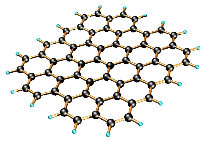
Graphene is a one-atom-thick planar sheet of sp2-bonded carbon atoms that are densely packed in a honeycomb crystal lattice (Figure \(\PageIndex{11}\)). The name comes from “graphite” and “alkene”; graphite itself consists of many graphene sheets stacked together.
Single-layer graphene nanosheets were first characterized in 2004, prepared by mechanical exfoliation (the “scotch-tape” method) of bulk graphite. Later graphene was produced by epitaxial chemical vapor deposition on silicon carbide and nickel substrates. Most recently, graphene nanoribbons (GNRs) have been prepared by the oxidative treatment of carbon nanotubes and by plasma etching of nanotubes embedded in polymer films.
Physical properties of graphene
Graphene has been reported to have a Young’s modulus of 1 TPa and intrinsic strength of 130 GP; similar to single walled carbon nanotubes (SWNTs). The electronic properties of graphene also have some similarity with carbon nanotubes. Graphene is a zero-bandgap semiconductor. Electron mobility in graphene is extraordinarily high (15,000 cm2/V.s at room temperature) and ballistic electron transport is reported to be on length scales comparable to that of SWNTs. One of the most promising aspects of graphene involves the use of GNRs. Cutting an individual graphene layer into a long strip can yield semiconducting materials where the bandgap is tuned by the width of the ribbon.
While graphene’s novel electronic and physical properties guarantee this material will be studied for years to come, there are some fundamental obstacles yet to overcome before graphene based materials can be fully utilized. The aforementioned methods of graphene preparation are effective; however, they are impractical for large-scale manufacturing. The most plentiful and inexpensive source of graphene is bulk graphite. Chemical methods for exfoliation of graphene from graphite provide the most realistic and scalable approach to graphene materials.
Graphene layers are held together in graphite by enormous van der Waals forces. Overcoming these forces is the major obstacle to graphite exfoliation. To date, chemical efforts at graphite exfoliation have been focused primarily on intercalation, chemical derivatization, thermal expansion, oxidation-reduction, the use of surfactants, or some combination of these.
Graphite oxide
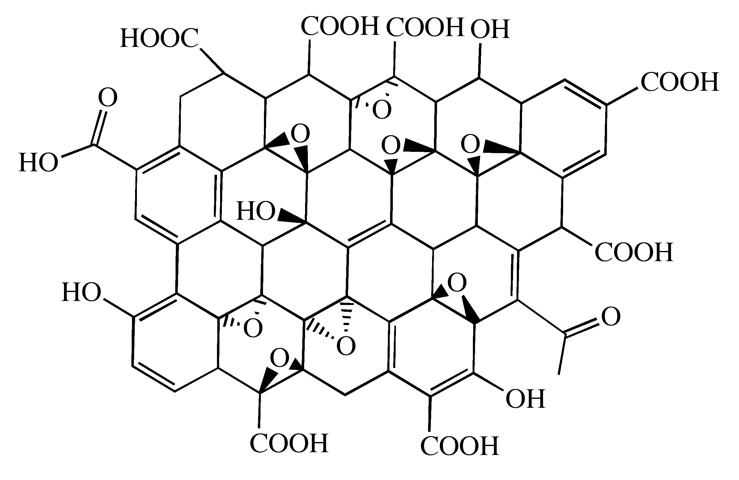
Probably the most common route to graphene involves the production of graphite oxide (GO) by extremely harsh oxidation chemistry. The methods of Staudenmeier or Hummers are most commonly used to produce GO, a highly exfoliated material that is dispersible in water. The structure of GO has been the subject of numerous studies; it is known to contain epoxide functional groups along the basal plane of sheets as well as hydroxyl and carboxyl moieties along the edges (Figure \(\PageIndex{12}\)). In contrast to other methods for the synthesis of GO, the the m-peroxybenzoic acid (m-CPBA) oxidation of microcrystalline synthetic graphite at room temperature yields graphite epoxide in high yield, without significant additional defects.
As graphite oxide is electrically insulating, it must be converted by chemical reduction to restore the electronic properties of graphene. Chemically converted graphene (CCG) is typically reduced by hydrazine or borohydride. The properties of CCG can never fully match those of graphene for two reasons:
- Oxidation to GO introduces defects.
- Chemical reduction does not fully restore the graphitic structure.
As would be expected, CCG is prone to aggregation unless stabilized. Graphene materials produced from pristine graphite avoid harsh oxidation to GO and subsequent (incomplete) reduction; thus, materials produced are potentially much better suited to electronics applications.
A catalytic approach to the removal of epoxides from fullerenes and SWNTs has been applied to graphene epoxide and GO. Treatment of oxidized graphenes with methyltrioxorhenium (MeReO3, MTO) in the presence of PPh3 results in the oxygen transfer, to form O=PPh3 and allow for quantification of the C:O ratio.
Homogeneous graphene dispersions
An alternate approach to producing graphene materials involves the use of pristine graphite as starting material. The fundamental value of such an approach lies in its avoidance of oxidation to GO and subsequent (incomplete) reduction, thereby preserving the desirable electronic properties of graphene. There is precedent for exfoliation of pristine graphite in neat organic solvents without oxidation or surfactants. It has been reported that N,N-dimethylformamide (DMF) dispersions of graphene are possible, but no detailed characterization of the dispersions were reported. In contrast, Coleman and coworkers reported similar dispersions using N-methylpyrrolidone (NMP), resulting in individual sheets of graphene at a concentration of ≤0.01 mg/mL. NMP and DMF are highly polar solvents, and not ideal in cases where reaction chemistry requires a nonpolar medium. Further, they are hygroscopic, making their use problematic when water must be excluded from reaction mixtures. Finally, DMF is prone to thermal and chemical decomposition.
Recently, dispersions of graphene has been reported in ortho-dichlorobenzene (ODCB) using a wide range of graphite sources. The choice of ODCB for graphite exfoliation was based on several criteria:
- ODCB is a common reaction solvent for fullerenes and is known to form stable SWNT dispersions.
- ODCB is a convenient high-boiling aromatic, and is compatible with a variety of reaction chemistries.
- ODCB, being aromatic, is able to interact with graphene via π-π stacking.
- It has been suggested that good solvents for graphite exfoliation should have surface tension values of 40 – 50 mJ/m2. ODCB has a surface tension of 36.6 mJ/m2, close to the proposed range.
Graphite is readily exfoliated in ODCB with homogenization and sonication. Three starting materials were successfully dispersed: microcrystalline synthetic, thermally expanded, and highly ordered pyrolytic graphite (HOPG). Dispersions of microcrystalline synthetic graphite have a concentration of 0.03 mg/mL, determined gravimetrically. Dispersions from expanded graphite and HOPG are less concentrated (0.02 mg/mL).
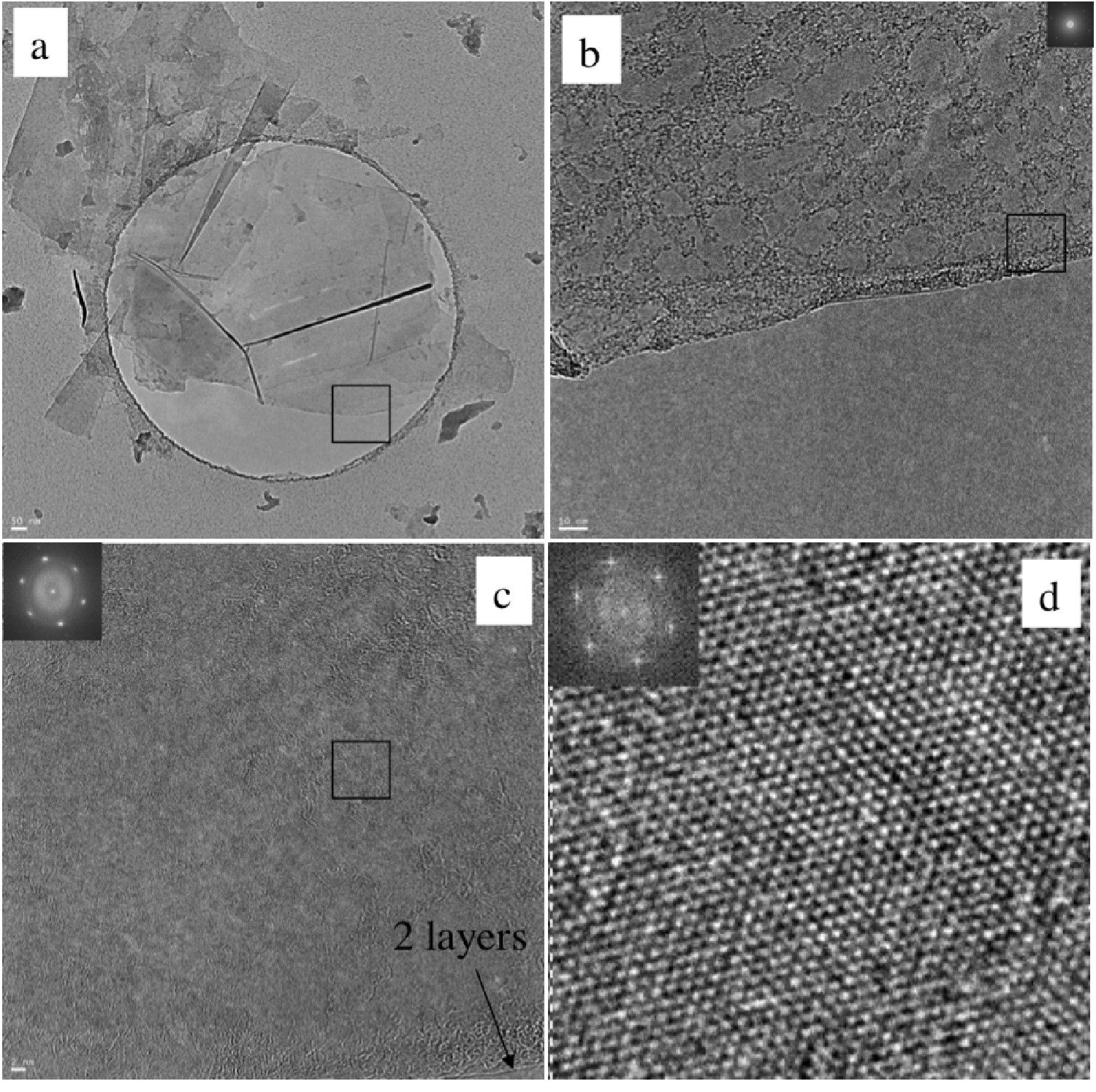
High resolution transmission electron microscopy (HRTEM) shows mostly few-layer graphene (n < 5) with single layers and small flakes stacked on top (Figure \(\PageIndex{13}\)). Large graphitic domains are visible; this is further supported by selected area electron diffraction (SAED) and fast Fourier transform (FFT) in selected areas. Atomic force microscope (AFM) images of dispersions sprayed onto silicon substrates shows extremely thin flakes with nearly all below 10 nm. Average height is 7 - 10 nm. The thinnest are less than 1 nm, graphene monolayers. Lateral dimensions of nanosheets range from 100 – 500 nm.
As-deposited films cast from ODCB graphene show poor electrical conductivity, however, after vacuum annealing at 400 °C for 12 hours the films improve vastly, having sheet resistances on the order of 60 Ω/sq. By comparison, graphene epitaxially grown on Ni has a reported sheet resistance of 280 Ω/sq.
Covalent functionalization of graphene and graphite oxide
The covalent functionalization of SWNTs is well established. Some routes to covalently functionalized SWNTs include esterification/ amidation, reductive alkylation (Billups reaction), and treatment with azomethine ylides (Prato reaction), diazonium salts, or nitrenes. Conversely, the chemical derivatization of graphene and GO is still relatively unexplored.
Some methods previously demonstrated for SWNTs have been adapted to GO or graphene. GO carboxylic acid groups have been converted into acyl chlorides followed by amidation with long-chain amines. Additionally, the coupling of primary amines and amino acids via nucleophilic attack of GO epoxide groups has been reported. Yet another route coupled isocyanates to carboxylic acid groups of GO. Functionalization of partially reduced GO by aryldiazonium salts has also been demonstrated. The Billups reaction has been performed on the intercalation compound potassium graphite (C8K), as well as graphite fluoride, and most recently GO. Graphene alkylation has been accomplished by treating graphite fluoride with alkyllithium reagents.
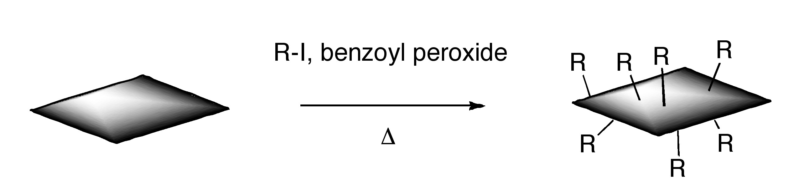
ODCB dispersions of graphene may be readily converted to covalently functionalize graphene. Thermal decomposition of benzoyl peroxide is used to initiate radical addition of alkyl iodides to graphene in ODCB dispersions.
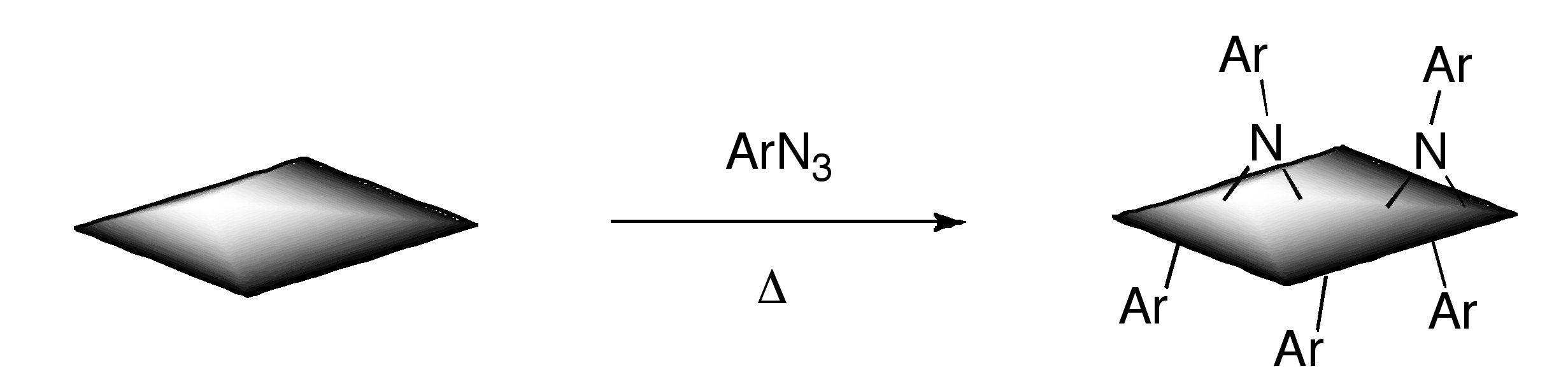
Additionally, functionalized graphene with nitrenes generated by thermal decomposition of aryl azides
Bibliography
- P. Blake, P. D. Brimicombe, R. R. Nair, T. J. Booth, D. Jiang, F. Schedin, L. A. Ponomarenko, S. V. Morozov, H. F. Gleeson, E. W. Hill, A. K. Geim, and K. S. Novoselov, Nano Lett., 2008, 8, 1704.
- J. Chattopadhyay, A. Mukherjee, C. E. Hamilton, J.-H. Kang, S. Chakraborty, W. Guo, K. F. Kelly, A. R. Barron, and W. E. Billups, J. Am. Chem. Soc., 2008, 130, 5414.
- G. Eda, G. Fanchini, and M. Chhowalla, Nat. Nanotechnol., 2008, 3, 270.
- M. Y. Han, B. Ozyilmaz, Y. Zhang, and P. Kim, Phys. Rev. Lett., 2008, 98, 206805.
- Y. Hernandez, V. Nicolosi, M. Lotya, F. M. Blighe, Z. Sun, S. De, I. T. McGovern, B. Holland, M. Byrne, Y. K. Gun’Ko, J. J. Boland, P. Niraj, G. Duesberg, S. Krishnamurthy, R. Goodhue, J. Hutchinson, V. Scardaci, A. C. Ferrari, and J. N. Coleman, Nat. Nanotechnol., 2008, 3, 563.
- W. S. Hummers and R. E. Offeman, J. Am. Chem. Soc., 1958, 80, 1339.
- L. Jiao, L. Zhang, X. Wang, G. Diankov, and H. Dai, Nature, 2009, 458, 877.
- D. V. Kosynkin, A. L. Higginbotham, A. Sinitskii, J. R. Lomeda, A. Dimiev, B. K. Price, and J. M. Tour, Nature, 2009, 458, 872.
- D. Li, M. B. Mueller, S. Gilje, R. B. Kaner, and G. G. Wallace, Nat. Nanotechnol., 2008, 3, 101.
- S. Niyogi, E. Bekyarova, M. E. Itkis, J. L. McWilliams, M. A. Hamon, and R. C. Haddon, J. Am. Chem. Soc., 2006, 128, 7720.
- Y. Si and E. T. Samulski, Nano Lett., 2008, 8, 1679.
- L. Staudenmaier, Ber. Dtsch. Chem. Ges., 1898, 31, 1481.