Overview of Lasers
- Page ID
- 80093
\( \newcommand{\vecs}[1]{\overset { \scriptstyle \rightharpoonup} {\mathbf{#1}} } \)
\( \newcommand{\vecd}[1]{\overset{-\!-\!\rightharpoonup}{\vphantom{a}\smash {#1}}} \)
\( \newcommand{\dsum}{\displaystyle\sum\limits} \)
\( \newcommand{\dint}{\displaystyle\int\limits} \)
\( \newcommand{\dlim}{\displaystyle\lim\limits} \)
\( \newcommand{\id}{\mathrm{id}}\) \( \newcommand{\Span}{\mathrm{span}}\)
( \newcommand{\kernel}{\mathrm{null}\,}\) \( \newcommand{\range}{\mathrm{range}\,}\)
\( \newcommand{\RealPart}{\mathrm{Re}}\) \( \newcommand{\ImaginaryPart}{\mathrm{Im}}\)
\( \newcommand{\Argument}{\mathrm{Arg}}\) \( \newcommand{\norm}[1]{\| #1 \|}\)
\( \newcommand{\inner}[2]{\langle #1, #2 \rangle}\)
\( \newcommand{\Span}{\mathrm{span}}\)
\( \newcommand{\id}{\mathrm{id}}\)
\( \newcommand{\Span}{\mathrm{span}}\)
\( \newcommand{\kernel}{\mathrm{null}\,}\)
\( \newcommand{\range}{\mathrm{range}\,}\)
\( \newcommand{\RealPart}{\mathrm{Re}}\)
\( \newcommand{\ImaginaryPart}{\mathrm{Im}}\)
\( \newcommand{\Argument}{\mathrm{Arg}}\)
\( \newcommand{\norm}[1]{\| #1 \|}\)
\( \newcommand{\inner}[2]{\langle #1, #2 \rangle}\)
\( \newcommand{\Span}{\mathrm{span}}\) \( \newcommand{\AA}{\unicode[.8,0]{x212B}}\)
\( \newcommand{\vectorA}[1]{\vec{#1}} % arrow\)
\( \newcommand{\vectorAt}[1]{\vec{\text{#1}}} % arrow\)
\( \newcommand{\vectorB}[1]{\overset { \scriptstyle \rightharpoonup} {\mathbf{#1}} } \)
\( \newcommand{\vectorC}[1]{\textbf{#1}} \)
\( \newcommand{\vectorD}[1]{\overrightarrow{#1}} \)
\( \newcommand{\vectorDt}[1]{\overrightarrow{\text{#1}}} \)
\( \newcommand{\vectE}[1]{\overset{-\!-\!\rightharpoonup}{\vphantom{a}\smash{\mathbf {#1}}}} \)
\( \newcommand{\vecs}[1]{\overset { \scriptstyle \rightharpoonup} {\mathbf{#1}} } \)
\(\newcommand{\longvect}{\overrightarrow}\)
\( \newcommand{\vecd}[1]{\overset{-\!-\!\rightharpoonup}{\vphantom{a}\smash {#1}}} \)
\(\newcommand{\avec}{\mathbf a}\) \(\newcommand{\bvec}{\mathbf b}\) \(\newcommand{\cvec}{\mathbf c}\) \(\newcommand{\dvec}{\mathbf d}\) \(\newcommand{\dtil}{\widetilde{\mathbf d}}\) \(\newcommand{\evec}{\mathbf e}\) \(\newcommand{\fvec}{\mathbf f}\) \(\newcommand{\nvec}{\mathbf n}\) \(\newcommand{\pvec}{\mathbf p}\) \(\newcommand{\qvec}{\mathbf q}\) \(\newcommand{\svec}{\mathbf s}\) \(\newcommand{\tvec}{\mathbf t}\) \(\newcommand{\uvec}{\mathbf u}\) \(\newcommand{\vvec}{\mathbf v}\) \(\newcommand{\wvec}{\mathbf w}\) \(\newcommand{\xvec}{\mathbf x}\) \(\newcommand{\yvec}{\mathbf y}\) \(\newcommand{\zvec}{\mathbf z}\) \(\newcommand{\rvec}{\mathbf r}\) \(\newcommand{\mvec}{\mathbf m}\) \(\newcommand{\zerovec}{\mathbf 0}\) \(\newcommand{\onevec}{\mathbf 1}\) \(\newcommand{\real}{\mathbb R}\) \(\newcommand{\twovec}[2]{\left[\begin{array}{r}#1 \\ #2 \end{array}\right]}\) \(\newcommand{\ctwovec}[2]{\left[\begin{array}{c}#1 \\ #2 \end{array}\right]}\) \(\newcommand{\threevec}[3]{\left[\begin{array}{r}#1 \\ #2 \\ #3 \end{array}\right]}\) \(\newcommand{\cthreevec}[3]{\left[\begin{array}{c}#1 \\ #2 \\ #3 \end{array}\right]}\) \(\newcommand{\fourvec}[4]{\left[\begin{array}{r}#1 \\ #2 \\ #3 \\ #4 \end{array}\right]}\) \(\newcommand{\cfourvec}[4]{\left[\begin{array}{c}#1 \\ #2 \\ #3 \\ #4 \end{array}\right]}\) \(\newcommand{\fivevec}[5]{\left[\begin{array}{r}#1 \\ #2 \\ #3 \\ #4 \\ #5 \\ \end{array}\right]}\) \(\newcommand{\cfivevec}[5]{\left[\begin{array}{c}#1 \\ #2 \\ #3 \\ #4 \\ #5 \\ \end{array}\right]}\) \(\newcommand{\mattwo}[4]{\left[\begin{array}{rr}#1 \amp #2 \\ #3 \amp #4 \\ \end{array}\right]}\) \(\newcommand{\laspan}[1]{\text{Span}\{#1\}}\) \(\newcommand{\bcal}{\cal B}\) \(\newcommand{\ccal}{\cal C}\) \(\newcommand{\scal}{\cal S}\) \(\newcommand{\wcal}{\cal W}\) \(\newcommand{\ecal}{\cal E}\) \(\newcommand{\coords}[2]{\left\{#1\right\}_{#2}}\) \(\newcommand{\gray}[1]{\color{gray}{#1}}\) \(\newcommand{\lgray}[1]{\color{lightgray}{#1}}\) \(\newcommand{\rank}{\operatorname{rank}}\) \(\newcommand{\row}{\text{Row}}\) \(\newcommand{\col}{\text{Col}}\) \(\renewcommand{\row}{\text{Row}}\) \(\newcommand{\nul}{\text{Nul}}\) \(\newcommand{\var}{\text{Var}}\) \(\newcommand{\corr}{\text{corr}}\) \(\newcommand{\len}[1]{\left|#1\right|}\) \(\newcommand{\bbar}{\overline{\bvec}}\) \(\newcommand{\bhat}{\widehat{\bvec}}\) \(\newcommand{\bperp}{\bvec^\perp}\) \(\newcommand{\xhat}{\widehat{\xvec}}\) \(\newcommand{\vhat}{\widehat{\vvec}}\) \(\newcommand{\uhat}{\widehat{\uvec}}\) \(\newcommand{\what}{\widehat{\wvec}}\) \(\newcommand{\Sighat}{\widehat{\Sigma}}\) \(\newcommand{\lt}{<}\) \(\newcommand{\gt}{>}\) \(\newcommand{\amp}{&}\) \(\definecolor{fillinmathshade}{gray}{0.9}\)LASER is an acronym for Light Amplification by Stimulated Emission of Radiation. Laser is a type of light source which has the unique characteristics of directionality, brightness, and monochromaticity. The goal of this module is to explain how a laser operates (stimulated or spontaneous emission), describe important components, and give some examples of types of lasers and their applications.
Introduction
The word LASER is an acronym for Light Amplification by Stimulated Emission of Radiation. In 1916, Albert Einstein discovered the physical principle responsible for this amplification, and the foundation principle is called stimulated emission. It was widely accepted at that time that laser would represent a big leap in science and technology, even before Theodore H. Maiman built the first one in 1960. The 1951 Nobel Prize in physics was shared by Charles H. Townes, Nokolay Basov, and Aleksandr Prokhorov, in citation, “For Fundamental work in the field of quantum electronics, which has led to the construction of oscillator and amplifiers based on the maser-laser principle”.
The early lasers developed in the 1950s by Charles H. Townes and Arthur Shawlow were gas and solid-state lasers for use in spectroscopy. The principles of lasers were adapted from masers. MASER is an acronym that stands for Microwave Amplification by Stimulated Emission of Radiation. It uses the idea of stimulated emission and population inversion to produce a coherent amplified radiation of light in the microwave region. Stimulated emission is when an electron in an excited state falls back to ground state after absorbing energy from an incident photon. Amplified radiation or light is produced with the same direction and energy as the incident light. Population inversion is when you have a greater population of electrons in the excited state than in ground state. Population inversion is achieved through various pumping mechanisms. The laser uses these same ideas except that the electromagnetic wave created is in the visible light region. When emission begins the light oscillates within the resonant cavity and gains magnitude. Once enough light has been acquired, the laser beam is produced. This allows lasers to be used as a powerful light source. Three unique characteristics of a laser are its properties of monochromaticity, directionality, and brightness.
The monochromaticity of lasers is due to the fact that lasers are highly selective in the wavelength of light produced, which in itself is due to the resonant frequency inside the active material. Resonant frequency means that the light is oscillating in a single mode creating a monochromatic beam of light. The property of directionality depends on the angle of which the light propagates out of the source. Since lasers have large spatial and temporal coherence directionality is maximized. Temporal coherence is when there are small fluctuations in the phase. Spatial coherence has small changes in the amplitude of the emitted light. Like monochromaticity, directionality is dependent on the resonant cavity of the active material. The property of brightness is a result of the directionality and the coherence of the light. Due to these properties, lasers today are used in simple laser pointers, cutting devices, the development of military technologies, spectroscopy, and medical treatments. Their direct application to spectroscopy has allowed scientists to measure lifetimes of excited state molecules, structural analysis, probing far regions of the atmosphere, photochemistry and their use as ionization sources.
History
One of the most important characteristics of light is that it has wave-like properties and that it is an electromagnetic wave. Experiments on the blackbody radiation demonstrated a comprehensive idea of emission and absorption of electromagnetic waves. In 1900, Max Plank developed the theory that electromagnetic waves can only exist in distinct quantities of energy, which are directly proportional to a given frequency (\(\nu\)). In 1905, Albert Einstein proposed the dual nature of light, having both wave-like and particle-like properties. He used the photoelectric effect to show that light acts as a particle, with energy inversely proportional to the wavelength of light. This is important, because the number of particles is directly related to how intense a light beam will be. In 1915, Einstein introduced the idea of stimulated emission- a key concept to lasers.
In 1957, Townes and Shawlow proposed the concept of lasers in the infrared and optical region by adapting the concept of masers to produce monochromatic and coherent radiation. In 1953, Townes was the first to build a maser with an ammonia gas source. Masers use stimulated emission to generate microwaves. Townes and other scientists wanted to develop the optical maser to generate light. Optical masers would soon adopt the name LASER: Light Amplification by Stimulated Emission of Radiation. An optical maser would need more energy than what can be provided by microwave frequencies and a resonant cavity of the order of 1μm or less. Townes and Shawlow proposed the use of a Fabry-Pérot interferometer equipped with parallel mirrors, where Interference of radiation which is traveling back and forth between parallel mirrors in the cavity allowed for selection of certain wavelengths. Townes built an optical maser with potassium gas. That failed because the mirrors degraded over time. In 1957, Gordon Gould improved upon Townes' and Shawlow's laser concept. It was Gould who renamed the optical maser to laser. In April 1959, Gould filed a patent for the laser and later in March 1960, Townes and Shawlow had also made a request for a patent. Since Gould’s notebook was officially dated the idea was his first, but he did not receive the patent until 1977.
Components
A laser consists of three main components: a lasing medium, a resonant or optical cavity, and an output coupler. The lasing medium consists of a group of atoms, molecules , or ions in solid, liquid or gaseous form, which acts as an amplifier for light waves. For amplification, the medium has to achieve population inversion, which means in a state in which the number of atoms in the upper energy level is greater than the number of atoms in the lower energy level. The output coupler serves as energy source which provides for obtaining such a state of population inversion between a pair of energy levels of the atomic system. When the active medium is placed inside an optical resonator, the system acts as an oscillator.
Lasing Medium
The lasing medium is the component used to achieve lasing, such as chromium in the aluminum oxide crystal-found in a ruby laser. Helium and neon gas are two materials most commonly used in gas lasers. These are only a few examples of lasing mediums or materials that have been used in the past and present states of the laser. For further information about different types of lasing mediums please refer to the section where Types of Lasers is discussed.
Optical Cavity and Output Coupler
Rays of light moving along an optical path tend to diverge over time, because the energy of radiation has very high frequency. Therefore an optical cavity is needed to refocus the light. Figure 1, represents the basics of an optical cavity where the light inside moves back and forth between two mirrors. These redirect and focus the light each time it hits the surface of the mirrors. There are two types of cavities: stable cavities and unstable cavities. A stable cavity is when the ray of light does not diverge far from the optical axis. An unstable cavity is when the ray of light bounces off and away from a mirrors surface. The importance of the cavities is that it allows for the laser to have properties of directionality, monochromaticity and brightness.
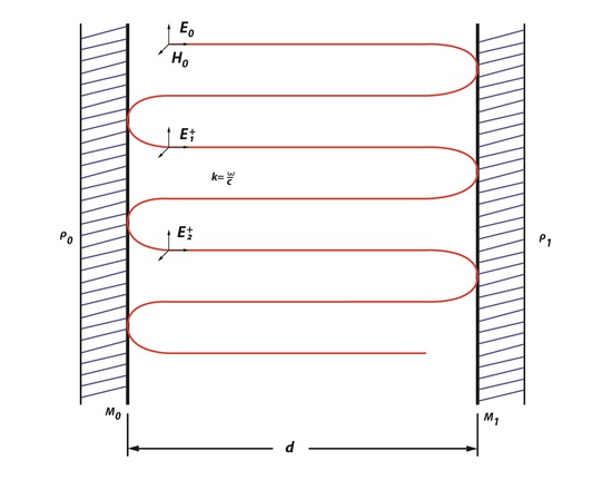
Light oscillating between the first mirror (Mo) and the second mirror (M1) separated by distance, d, will have a round-trip phase shift (RTPS) of 2θ=2kd=q2π- ϕ. In Figure 1, a round-trip can be described as the beam traveling from Mo to M1back to Mo. Resonance occurs in the cavity because the light propagating between the two mirrors is uniform. The ABCD law describes that an optical cavity has a field distribution, because it reproduces itself as it is making these round-trips between the two parallel mirrors. The ABCD law was first applied to a Gaussian beam with a beam parameter, q, which is described as
\[q_2=\dfrac {(Aq_1+B)}{(Cq_1+D)} \nonumber \]
This law states that the beam, which is oscillating through an optical system, will experience some changing as it moves in the cavity. Fields that are created in an optical cavity have analogous shape and phase as they make each trip back and forth. However, the one thing that changes is the size of the field because the electromagnetic wave is unrestricted, unlike a wave in a short-circuited coaxial cable used to build a resonator or a microwave cavity mode. Since there is a field distribution of Eoat the surface of Mo, it can be said that there is a field distribution at the surface of M1. Since there will be a change in size of the field this means that the electromagnetic wave will have change in amplitude by ρ0*ρ1 and a phase factor of \(e^-jk2d\), creating additional fields. This is an example of a phasorial addition of all fields between Mo and M1, creating a total field ET (Figure 2). Phasorial addition is described by RTPS, where each additional En will have a delay of angle ϕ which is related to kd.
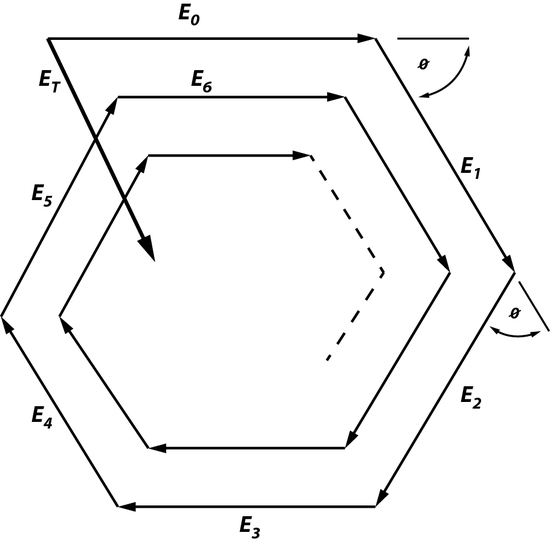
ET will always be greater than Eoonly if ρ0 and ρ1are not greater than 1 and ϕ=0. In this case, when ϕ=0 resonance is enhanced because all factors such as ET travelling between Mo and M1, the intensity of the electromagnetic waves, number of photons traveling between Moand M1, and the amount of energy that is stored are maximized. The resonant wavelength can also be determined by using the relationship between RTPS, and because
\(k=\dfrac {\omega n}{c}=\dfrac {2\pi}{\lambda}\)
Using \(2\theta=2kd=q2\pi\)
\(\dfrac{2\pi2d}{\lambda}=q2π\)
\(d=\dfrac {q\lambda}{2}\)
Where the wavelength of interest is given by \(\lambda=\lambda_0/n\), where n is the index of refraction and \(\lambda_0\) is the free-space wavelength .
Since we are dealing with light as a wave, the light in the resonant cavity can be described in terms of frequency, ν. Where
\(k2d=\omega\dfrac {2nd}{c}=2\pi \nu \dfrac {2nd}{c}=q(2\pi)\)
\(\nu=q\dfrac {c}{2nd}\)
A Fabry-Pérot interferometer is a prime example of an optical cavity used in a laser. The Fabry-Pérot is equipped with two parallel mirrors, one that is completely reflective and the other that is partially reflective. As light is accumulating in the cavity after taking several round trips between the two mirrors, some light is transmitted through the partially reflective mirror and a laser beam is produced. The beam can be in pulsed mode or continuous-wave (CW) mode. To increase the performance of the resonant cavity, the length of the cavity (d) must be considered as a way to avoid a decrease in the laser beam intensity due to any diffraction losses. The size of the aperture of the cavity is also important because it determines the strength or the intensity of the laser beam. In fact, determining the best length of a resonant cavity will enhance the coupling conditions of the output coupler by producing a frequency that is stable, which ultimately generates a laser beam that is coherent and has high power.
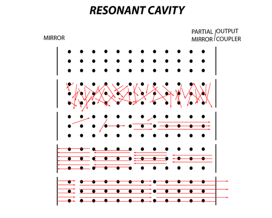
There are essentially six stages in the lasing process. First is the ground state where there is no excitation of the lasing medium. Second is pumping, which is applied to the medium where spontaneous emission occurs. Then the third stage is when emitted photons collide with an excited molecule where stimulated emission occurs. In the fourth stage the photons are produced in multiples, however those moving parallel in the cavity will hit a mirror and then hit the second mirror. During the fifth stage this process continues until there is an accumulation of light that is coherent and of a specific frequency. Finally, the sixth stage is when the light or laser beam exits the partially reflective mirror which is also known as the output coupler. An output coupler is the last important component of a laser because it must be efficient to produce an output of light with maximum intensity. If the output coupler is too transparent than there is much more loss of electromagnetic waves and this will decrease lasing significantly because population inversion will no longer be maintained. If the output coupler or partially reflective mirror is too reflective, then all the accumulated light that is built up in the resonant cavity will be trapped in the cavity. The beam will not pass through the output coupler, producing little to no light making the laser ineffective.
Emission
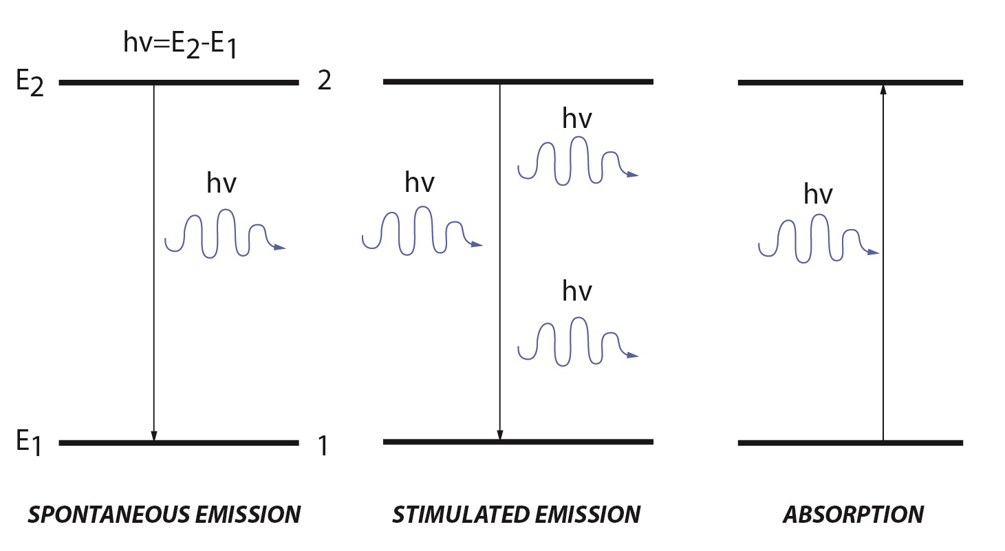
Lasers create a high energy beam of light by stimulated emission or spontaneous emission. Within in a molecule there are discrete energy levels. A simple molecular description has a low energy ground state (E1) and a high energy excited state (E2). When an electromagnetic wave, referred to as the incident light, irradiates a molecule there are two processes that can occur: absorption and stimulated emission.
Absorption occurs when the energy of the incident light matches the energy difference between the ground and excited state, causing the population in the ground state to be promoted to the excited state. The rate of absorption is given by the equation:
\(\dfrac {dN_1}{dt}=-W_{12} N_1\)
Where N1 is the population in E1, and W12 is the probability of this transition. The probability of the transition can also be related to the photon flux (intensity of incident light):
\(W_{12}=\sigma_{12} F\)
Where F is the photon flux and σ12 is the cross section of the transition with units of area. When absorption occurs photons are removed from the incident light and the intensity of the light is decreased.
Stimulated emission is the reverse of absorption. Stimulated emission has two main requirements: there must be population in the excited state and the energy of the incident light must match the difference between the excited and ground state. When these two requirements are met, population from the excited state will move to the ground energy level. During this process a photon is emitted with the same energy and direction as the incident light. Unlike absorption, stimulated emission adds to the intensity of the incident light. The rate for stimulated emission is similar to the rate of absorption, except that it uses the population of the higher energy level:
\(W_{21}=\sigma_{21} F\)
Like absorption the probability of the transition is related to the photon flux of the incident light through the equation:
\(\dfrac {dN_2}{dt}=-W_{21} N_2\)
When absorption and stimulated emission occur simultaneously in a system the photon flux of the incident light can increase or decrease. The change in the photon flux is a combination of the rate equations for absorption and stimulated emission. This is given by the equation:
\[dF=\sigma F(N_2-N_1 )d\tau \nonumber \]
Spontaneous emission has the same characteristics as stimulated emission except that no incident light is required to cause the transition from the excited to ground state. Population in the excited state is unstable and will decay to the ground state through several processes. Most decays involve non-radiative vibrational relaxation, but some molecules will decay while emitting a photon matching the energy of the energy difference between the two states. The rate of spontaneous emission is given by:
\[\dfrac {dN_2}{dt}=-AN_2 \nonumber \]
Where A is the spontaneous emission probability which depends on the transition involved. The coefficient A is an Einstein coefficient obtained from the spontaneous emission lifetime. Since spontaneous emission is not competing with absorption, the photon flux is based solely on the rate of spontaneous emission.
The population ratio of a molecule or atom is found using the Boltzmann distribution and the energy of the ground state (E1) and the excited state (E2):
\[ \dfrac{N_2}{N_1} = e^{\dfrac{-(E_2-E_1)}{kT}} \nonumber \]
Under normal conditions, the majority, if not all, of the population is in the lower energy level (E1). This is because the energy of the excited is greater than the ground state. Normal thermal energy available (kT) is not enough to overcome the difference, and the ratio of population favors the ground state. For example, if the difference in energy between two states absorbes light at 500nm, the ratio of N1 to N2 is 5.1x1041:1. The photon flux of the incident light is directly proportional to the difference in populations. Since the ground state has more populations, the photon flux decreases: there is more absorption occurring than stimulated emission. In order to increase the photon flux there must be more population in the excited state than in the ground state, generally known as a population inversion.
In a two level energy system it is impossible to create the population inversion needed for a laser. Instead three or four level energy systems are generally used (Figure 5).
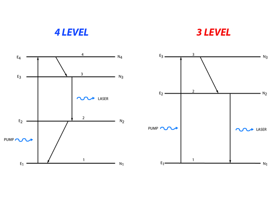
Three level processes involve pumping of population from the lowest energy level to the highest, third energy state. The population can then decay down to the second energy level or back down to the first energy level. The population that makes it to the second energy level is available for stimulated emission. Light matching the energy difference between the second and first energy level will cause a stimulated emission. Four level systems follow roughly the same process except that population is moved from the lowest state to the highest fourth level. Then it decays to the third level and lasing happens when the incident light matches the energy between the third and second level. After lasing there is decay to the first level.
Pumping Process
Pumping is the movement of population from the ground state to a higher excited state. The general rate at which this is done is given by:
\((\dfrac {dN_g}{dt})_p=W_p N_g\)
Where Ng is the population in the ground level and Wp is the pump rate. Pumping can be done optically, electronically, chemically (see chemical laser), using gases at high flow rates, and nuclear fission. Only optical and electrical pumping will be discussed in detail.
Optical Pumping
Optical pumping uses light to create the necessary population inversion for a laser. Usually high pressure xenon or krypton lamps are used to excite solid or liquid laser systems. The active material in the laser absorbs the light from the pump lamp, promoting the population from the ground state to the higher energy state. The material used in the laser can be continuously exposed to the pumping light which creates a continuous wave laser (CW). A pulsed laser can be created by using flashes of pumping light.
In optical pumping there are three types of efficiency: transfer, lamp radiative, and pump quantum efficiency. Transfer efficiency is the ratio of the energy created by the lamp and the power of the light emitted by the laser. The lamp radiative efficiency is the measure of how much electrical power is converted into light in the optical lamp. Pump quantum efficiency accounts for the ratio of population that decays to the correct energy level and population that decays either back to the ground state or another incorrect energy level. For example, the overall pumping rate of the first ruby laser was around 1.1%.
The average pump rate for optical pumping depends on the total efficiency of the pump (\(η_p\)), volume of the laser material (V), ground state population (Ng), power input (P), and frequency of the lasing transition (ν0):
\(〈W_p 〉=\eta_p (P/(VN_g ℏυ_0 ))\)
Electrical Pumping
Electrical pumping is a much more complicated process than optical pumping. Usually used for gas and semiconducting lasers, electrical pumping uses electrical current to excite and promote the ground state population. In a simple gas laser that contains only one species (A), current passes through the gas medium and creates electrons that collide with the gas molecules to produce excited state molecules (A*):
\(A+e \longrightarrow A^*+e\)
During electron impact either an ion or an excited state can be created. The ability to make the excited state depends mostly on the material used in the laser and not the electrical pumping source making it difficult to describe the efficiency of the pumping. Total efficiencies have been calculated and tabulated for most active materials used in electrical pumping. Where eficiencies range from a < 0.1% N2 gas laser to 70% for some CO2 gas lasers.
Like the pumping rate of optical pumps, the rate of electrical pumping is found using the overall efficiency of the pump, power applied, and population of the ground state. However instead of using the frequency of the ground to upper state transition, electrical pumping uses the energy of the upper state (ħωp) and the volume of the electron discharge (V):
\(〈W_p 〉=\eta_p (P/(VN_g ℏω_p ))\)
Pulsed operation
Q-Switching
The technique of Q switching allows the generation of laser pulses of short duration from a few nanoseconds to a few tens of nanoseconds and high peak power from a few megawatts to a few tens of megawatts.
Suggest we put a shutter into the laser cavity. If the shutter is closed, laser action cannot occur and the population inversion can be very high. If the shutter is opened suddenly, the stored energy will be released in a short and intense light pulse. This technique is known as Q-switching. Q here denotes the ratio of the energy stored to the energy dissipated in the cavity. This technique is used in many types of solid-stat lasers and CO2 lasers to get a high-power pulsed output.
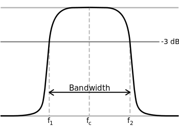
To produce high inversion required for Q-switching, four requirements must be satisfied.
- The lifetime of the upper level must be longer than cavity buildup time.
- The pumping flux duration must be longer than the cavity build up time.
- The initial cavity losses must be high enough during the pumping duration to prevent oscillation occurring.
- The cavity losses must be reduced instantaneously.
Mode-Locking
The technique of mode locking allows the generation of laser pulses of ultrashort duration from less than a picosecond to femtoseconds and very high peak, a few gigawatts.
Mode-locking is achieved by inducing the different longitudinal modes of a laser to a locked mode. When combining the electromagnetic waves modes with different frequencies and random phases, they produce a random and average output. When the modes are added in phase, they combine to produce a total amplitude and intensity output with a repeated pulse.
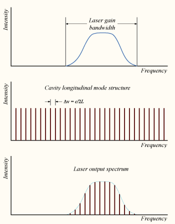
FIgure 8:Laser mode structure
Types of Lasers
There are many different types of lasers with a wide range applications, and below is a brief description of some of the main types.
Solid State Lasers
A solid-state laser is one that uses a solid active medium generally in a rod shape. Inside the active material is a dopant that acts as the light emitting source. Optical pumping is used to create population inversion of the active material. Solid-state lasers generally use stimulated emission as the mechanism for creating the high energy beam.
Ruby Laser
The ruby laser was the first operating laser and was built in 1960. It has a three-level (Figure 6) energy system that uses aluminum oxide with some of the aluminum atom replaced with chromium as its active material. The chromium in the aluminum oxide crystal is the active part of the laser. Electrons in the ground state of chromium absorb the incident light and become promoted to higher energy states. The short lived excited state relaxes down to a metastable state with a longer lifetime. Laser emission happens when there is relaxation from the metastable state back to the ground state.
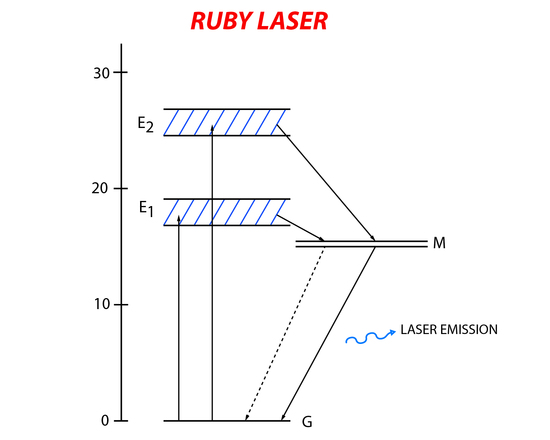
A xenon flash lamp emitting light at wavelengths of 6600Å and 4000Å (matching the energy needed to excite the chromium atoms). In order to create resonance of the incident light in the active material silver platting was put at both ends of the ruby rod. One end was completely covered while the other end was partially covered so lasing light could exit the system.
Nd: YAG Laser
Nd: YAG laser are the most popular type of solid state laser. The laser medium is a crystal of Y3Al5O12 which are commonly called YAG, an acronym for yttrium aluminum garnet. A simplified energy-level scheme for Nd:YAG is shown in Fig. 9. The λ=1.06 μm laser transition is the strongest of the 4F3/2→4I11/2 transitions.
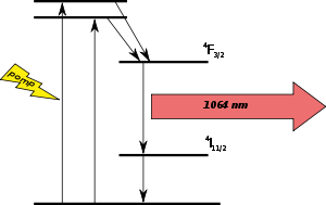
The major application of the Nd laser is in various form of material processing: drilling, spot welding, and laser marking. Because they can be focused to a very small spot, the laser are also used in resistor trimming and in circuit mask , memory repair and also in cutting out specialized circuits. Medical applications include many types of surgeries. Many medical applications take advantage of low-loss optical fiber delivery systems that can be inserted into the body to wherever is needed. Nd lasers are also used in military applications such as range finding and target designation. High power pilsed versions are also used for X-ray spectral regions. In addition, Nd lasers are used in scientific lab as good sources for pumping dye laser and other types of lasers.
Semiconductor Laser
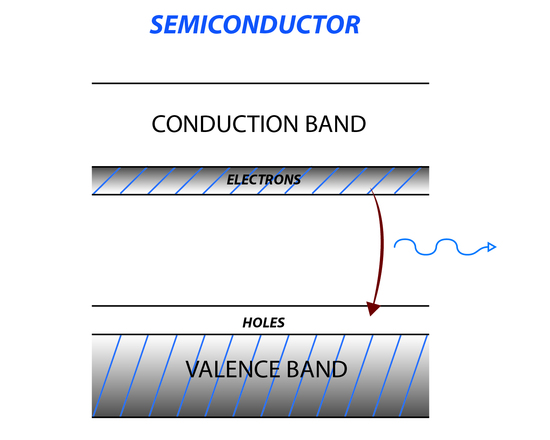
The semiconductor laser is another type of solid state laser that uses a semiconducting material like germanium or silicon. When the temperature of the semiconducting material is increased, electrons move from the valence band to the conducting band creating holes in the valence band (Figure 7). In between the conducting band and valence band is a region where there are no energy levels, called the band gap. Applying a voltage to the semiconductor causes electrons to move to the conduction band creating a population inversion. Irradiating a semiconductor with incident light matching the energy of the forbidden area causes a large transition from the conduction band to the valence band, increasing and amplifying the incident light.
Gas Lasers
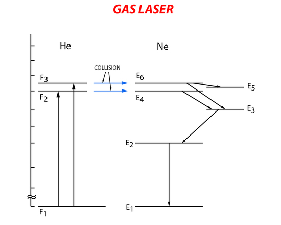
A gas laser contains active material composed of a mixture of gases with similar energy states inside a small gas chamber. Electrical pumping is used to create the population inversion where one gas is excited through collisions with electrons and in turn excites the other gas through collisions.
Helium-Neon Laser
The helium-neon laser was the first gas laser. It consists of a long narrow tube that contains He and Ne gas. Mirrors are placed at both ends of the gas tube to form the resonant cavity with one of the mirrors partially reflecting the incident light. Stimulated emission of the gas mixture is carried out by first exciting the He gas to a higher energy state through electron collision with electrons from the electronic pumping source (electrical pumping). Then the excited He atoms collide with the Ne atoms transferring their energy and exciting them to a higher energy level. The Ne atoms in the higher energy level will then relax to a lower metastable energy state. Lasing occurs when there is relaxation from the metastable state to a lower energy state causing spontaneous emission. The Ne gas then returns to the ground state when it collides with the outer walls of the gas tube (Figure 8).
Carbon Dioxide Laser
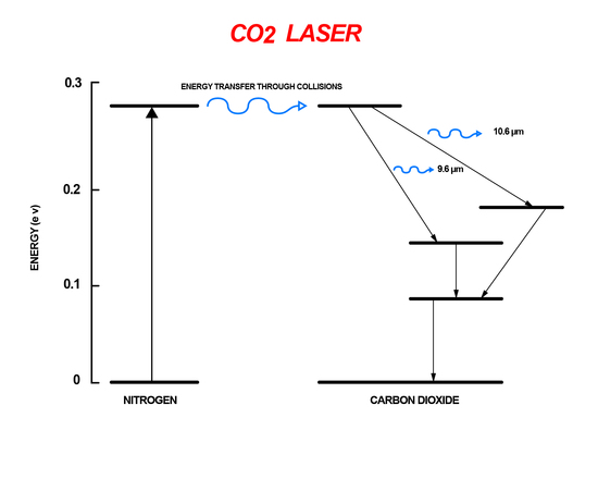
The carbon dioxide laser is a gas laser that uses the energy difference between rotational-vibrational energy levels. Within the vibrational levels of CO2 there are rotational sub-energy levels. A mixture of N2 and CO2 gas are placed inside a chamber. The N2 atoms are excited through an electrical pumping mechanism. The excited atoms then collide with the CO2 atoms transfer energy. This transfer of energy causes the CO2 to go into a higher vibrational level. The excited CO2 molecules then go through spontaneous emission when they are relaxed to lower rotational-vibrational levels increasing the signal of the incident light (Figure 9). Carbon dioxide lasers are extremely efficient, around 70%, and powerful compared to other gas lasers making them useful for welding and cutting.
Liquid Lasers
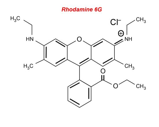
Liquid lasers consist of a liquid active material usually composed of an organic dye compound. The most common type of liquid laser uses rhodamine 6G (Figure 10) dye mixed with alcohol and is excited by different types of lasers, such as an argon-ion laser or a nitrogen laser. Organic dyes are large compounds that have absorption bands in the UV or visible region with a strong intense fluorescence spectrum. The free π electrons of the dye are excited using an optical pumping source and the transition from the S1 to the S0 state creates the lasing light (see Jablonski diagrams). Liquids are generally used because they can easily be tuned to emit a certain wavelength by changing the resonant frequency within the cavity. Wavelengths from the visible to the infrared can be covered. There are many benefits of liquid lasers, some include that they can be cooled in a relative amount of time, they cannot be damaged unlike a solid-laser, and their production is cost-effective. The efficiency of liquid lasers is low because the lifetime of the excited state is relatively short; there are many non-radiative decay processes, and the material degrades over time. Liquid lasers tend to be used only as a pulse laser when tunability is required. Liquid lasers can be used for high-resolution spectroscopy since they are easily tuned over a wide range of wavelengths. They can also be used because they have concentrations which are manageable when dissolved in solids or other liquids.
Chemical Lasers
Chemical lasers are different from other lasers because the population inversion is the direct product of a chemical reaction when energy is released as a result of an exothermic reaction. Usually reactions involve gases where the energy created is used to make vibrationally excited molecules. Light used for lasing is then created from vibrational-rotational relaxation like in the CO2 gas laser. An example of a chemical laser is the HF gas laser. Inside the gas chamber fluorine and hydrogen react to form an excited HF molecule:
F + H2 → HF + H
The excess energy from the reaction allows HF to stay in its excited state. As it relaxes, light is emitted through spontaneous emission. Deuterium can also be used in place of hydrogen. Deterium fluoride is useds for applications that require high-power. For example, MIRACL was built for military research and was known to produce 2.2 megawatts of power. The uniqueness of a chemical laser is that the power required for lasing is produced in the reaction itself.
Laser Applications
The applications of lasers are numerous and cover scientific and technological fields. In general, these applications are a direct consequence of the special characteristics of lasers. Below are a few examples of the laser applications, for a complete list please go to en.Wikipedia.org/wiki/List_of...ons_for_lasers
Lidar
Lidar is short for light detection and ranging which is an optical remote sensing technology can be used for monitoring the environment. A typical lidar system involves a transmitter of laser radiation and a receiver for the detection and analysis of backscattered light. A beam expander is usually used at transmitter to reduce divergence of the laser beam before it propagates into the atmosphere. The receiver includes a wavelength filter, a photo detector, and computers and electronics for data acquisition and analysis.
Lidar system dates back to the 1930, because of the laser, it has become one of the primary tools in atmospheric and environmental research. Other than that, Lidar has been put into various uses. In agriculture, lidar can be used to create topographic map to help farmer to decide appropriate amount of fertilizing to achieve a better crop yield. In Archaeology, lidar can be used to create a geographic information system to help archaeologists to find sites. In transportation, lidar has been used in autonomous cruise control system to prevent road accident and policemen are also using lidar speed gun to enforce the speed limit regulation.
Laser in Material Processing
The beam of a laser is usually a few millimeters in diagram. For most material processing applications, lenses are used to increase the intensity of the beam. The beam from a laser is either plane or spherical. After passing through a lens, the beam should get focused to a point. But in actual practice, diffraction effects have to be taken into consideration, the incoming will focus into a region of radius. If λ is the wavelength of the laser light, a is the radius of the beam, and f is the focal length of the lens, then the radius of the region is
\(b =\dfrac {\lambda f }{ a }\)
If P represents the power of the laser beam, the intensity I, obtained at the focused region would be given by,
\(I =\dfrac { P }{ \pi b^2 }=\dfrac { P a^2 }{ \pi πλ^2f^2 }\)
The high-power (P>100w) laser are widely used in material processing such as welding, drilling, cutting, surface treatment, and alloying. The main advantage of the laser beam can be summarized as follow: (1) The heating produced by the laser is less than that in conventional process. Material distortion is considerably reduced. (2) Possibility of working in inaccessible region. Any region which can be seen can be processed by a laser. (3) The process can be better controlled and easily automatized. However, against all these advantages, the disadvantages are: (1) high cost of the laser system. (2) Reliability and reproducibility problems of the laser system. (3) Safety problems.
Laser in Medicine
In field of medicine, the major use of lasers is for surgery such as laser eye surgery commonly known as LASIK. Besides that, there are also a few diagnosetic applications such as clinical use of flow microfluormeters, Doppler velocimetry to measure the blood velocity, laser fluorescence bronchoscope to detect tumors in their early phase.
For surgery, the laser beams are used instead of a conventional scalpel. The infrared beam from the CO2 laser is strongly absorbed by water molecules in the tissue. It produces a rapid evaporation of these molecules, consequently cutting the tissue. The main advantage of laser beam surgery can be summarized as follows: (1) High precision. The incision can be made with a high precision particularly when the beam is directed by means of a microscope. (2) Possibility of operating in inaccessible region. Laser surgery can be operated in any region of the body which can be observed by means of an optical system. (4) Limited damage to blood vessel and adjacent tissue. However, the disadvantages are: (1) considerable cost. (2) Smaller velocity of the laser scalpel. (3) Reliability and safety problems associated with the laser procedure.
References
- Arias, P., Jaeckey, J., Redondo, J., & Ringwald, A. (2010). Optimizing light-shining-through-a-wall experiments for axion and other weakly interacting slim particle searches. The American Physical Society, 82(11), DOI: 10.1103/PhysRevD.82.11501
- Bertolotti, M. (1999). The History of the Laser. Philadelphia, PA: Institute of Physics Publishing.
- Ferrai, G., et al. (2010). Coherent Addition of Laser Beams in Resonant Passive Optical Cavities. OpticsInfoBase, 35(18), DOI: 10.1364/OL.35.003105
- Hecht, J. (1992). Laser pioneers. San Diego, CA: Academic Press Limited.
- Horn, D. T. (1988). Laser experimenter's handbook. Blue Ridge Summit, PA: Tab Books Inc.
- Kenichi, I. (1988). Fundamentals of Laser Optics. Yokohama, Japan: Plenum Press.
- Khanin, Y. (1995). Principles of Laser Dynamics. (P. Press, Ed.) New York, NY: Elsevier.
- Verdeyen, J. (1989). Laser Electronics. Englewood Cliffs, NJ: Prentice-Hall, Inc.
- Milonni,P.,Eberly, J., (2010) Laser Physics.Hoboken NJ:John Wiley&Sons, Inc.
- Silfvast,W.,(1996) Laser Fundamentals. New York,NY: the Press Syndicate of the university of Cambridge.
- Thyagarajan, K. (1981) Lasers: Theory and Application. New York, NY: Plenum Press.
- Hooker,S., Webb,C., (2010) Laser Physics. Oxford, NY:Oxford University Press.
- Svelto, O. (1982). Principles of Lasers. (2nd, Ed.) New York, NY: Plenum Press.
- Coherent, I. (Ed.). (1980). Lasers Operation, Equipment, Application and Design. Palo Alto, CA: McGraw-Hill.
Outside Links
- http://en.Wikipedia.org/wiki/Laser
- en.Wikipedia.org/wiki/List_of_laser_types
- en.Wikipedia.org/wiki/Q_factor
- en.Wikipedia.org/wiki/Mode-locking
Problems
- Determine the free-space wavelength (\(\lambda_0\)) in Å, and frequency of the resonant cavity for a beam parameter q1 that is 632,110 and q2 that is 632,111 in a helium-neon gas laser at 1 atm. The index of refraction n is 1.00, the length of the resonant cavity is 20 cm and the wavelength region of interest is 6328Å.
- What wavelength of light will be released by the spontaneous emission of Ne gas, where the the energy difference between the excited and ground state is 9.9 x 10⁻¹⁹ J.
- What is the population ratio of the above question at 300K.
Answers
- For q1 \(\lambda_0=6328.0125 \angstrom \) Å, q2 \(\lambda_0=6328.0025 \angstrom \) Å, and v=474 THz for both q values
- 200 nm
- N2/N1=1.9 x 10-105
Contributors and Attributions
- Greg Allen (UCD), Arpana Vaniya (UCD), Zheng Zhang (UC Davis)

