5.1: Using Optical Transforms to Teach Quantum Mechanics
- Page ID
- 149589
\( \newcommand{\vecs}[1]{\overset { \scriptstyle \rightharpoonup} {\mathbf{#1}} } \)
\( \newcommand{\vecd}[1]{\overset{-\!-\!\rightharpoonup}{\vphantom{a}\smash {#1}}} \)
\( \newcommand{\id}{\mathrm{id}}\) \( \newcommand{\Span}{\mathrm{span}}\)
( \newcommand{\kernel}{\mathrm{null}\,}\) \( \newcommand{\range}{\mathrm{range}\,}\)
\( \newcommand{\RealPart}{\mathrm{Re}}\) \( \newcommand{\ImaginaryPart}{\mathrm{Im}}\)
\( \newcommand{\Argument}{\mathrm{Arg}}\) \( \newcommand{\norm}[1]{\| #1 \|}\)
\( \newcommand{\inner}[2]{\langle #1, #2 \rangle}\)
\( \newcommand{\Span}{\mathrm{span}}\)
\( \newcommand{\id}{\mathrm{id}}\)
\( \newcommand{\Span}{\mathrm{span}}\)
\( \newcommand{\kernel}{\mathrm{null}\,}\)
\( \newcommand{\range}{\mathrm{range}\,}\)
\( \newcommand{\RealPart}{\mathrm{Re}}\)
\( \newcommand{\ImaginaryPart}{\mathrm{Im}}\)
\( \newcommand{\Argument}{\mathrm{Arg}}\)
\( \newcommand{\norm}[1]{\| #1 \|}\)
\( \newcommand{\inner}[2]{\langle #1, #2 \rangle}\)
\( \newcommand{\Span}{\mathrm{span}}\) \( \newcommand{\AA}{\unicode[.8,0]{x212B}}\)
\( \newcommand{\vectorA}[1]{\vec{#1}} % arrow\)
\( \newcommand{\vectorAt}[1]{\vec{\text{#1}}} % arrow\)
\( \newcommand{\vectorB}[1]{\overset { \scriptstyle \rightharpoonup} {\mathbf{#1}} } \)
\( \newcommand{\vectorC}[1]{\textbf{#1}} \)
\( \newcommand{\vectorD}[1]{\overrightarrow{#1}} \)
\( \newcommand{\vectorDt}[1]{\overrightarrow{\text{#1}}} \)
\( \newcommand{\vectE}[1]{\overset{-\!-\!\rightharpoonup}{\vphantom{a}\smash{\mathbf {#1}}}} \)
\( \newcommand{\vecs}[1]{\overset { \scriptstyle \rightharpoonup} {\mathbf{#1}} } \)
\( \newcommand{\vecd}[1]{\overset{-\!-\!\rightharpoonup}{\vphantom{a}\smash {#1}}} \)
Abstract: Wave-particle duality, the superposition principle, the uncertainty principle, and single-particle interference are the most fundamental quantum mechanical concepts. The purpose of this paper is to demonstrate that these quantum mechanical principles are illuminated by a study of diffraction patterns created with laser light and a variety of two-dimensional masks.
The principles of X-ray crystallography are generally taught using the Bragg model in which X-rays irradiating a crystal behave as classical waves reflected by planes of atoms producing a characteristic diffraction pattern determined by the Bragg interference condition. Optical transform kits developed by the Institute for Chemical Education [1-4] and similar resources [5] have been used to teach these principles through classroom demonstrations of the diffraction patterns generated by laser light and two-dimensional masks. The purpose of this paper is to show that these same teaching aids can be used to teach quantum mechanical principles to chemistry majors in upper-division courses. The quantum concepts illuminated in this approach are
• wave-particle duality,
• the superposition principle,
• the uncertainty principle,
• single-particle interference,
• the quantum mechanical view of experimentation.
Our approach to using optical transforms is an extension of the method Marcella used recently to analyze the famous double-slit experiment [6, 7]. In what follows, the relationship of optical transforms to the quantum mechanical principles listed above is presented as concisely as possible while supporting information is relegated to footnotes and appendices.
Marcella identified three steps in a quantum mechanical experiment: (1) state preparation, (2) measurement of an observable property, and (3) comparison of experimental results with theoretical calculations. We will introduce Marcella's method with a review of the double-slit experiment and then extend this approach to optical transforms of other two-dimensional masks.
According to Richard Feynman the double-slit experiment is the paradigm for all quantum mechanics because it is a simple manifestation of the superposition principle, which is quantum theory is "only mystery" [8]. Stressing the fundamental importance of the double-slit experiment he said that any question in quantum mechanics could always be answered with the response, "You remember the experiment with the two holes? It is the same thing" [9].
In the double-slit experiment the apparatus consists of a source of particles (photons, electrons, neutrons, He atoms, C60 molecules, etc.; see reference 14 and papers cited therein), a slit-screen, and a detection screen. Wave-particle duality is manifested in this experiment as follows. The source creates particles and the detector registers particles, but between source and detector the behavior is wave-like. This is the underlying structure for all quantum mechanical experiments.
State preparation occurs at the slit screen where the particle is position is localized at holes or slits. According to quantum mechanical principles the coordinate-space wave function at the slit screen is a linear superposition describing the particle as present at both slits simultaneously. To begin we will treat the slits as point holes in a screen at (x1, y1) and (x2, y2). This view yields the following coordinate-space wave function [10].
\[ | \Psi \rangle = \frac{1}{ \sqrt{2}} \left[ x_1,~ y_1 \rangle + |x_2,~y_2 \rangle \right] = \frac{1}{ \sqrt{2}} \sum_{i=1}^2 |x_i,~y_i \rangle \nonumber \]
In Marcella's quantum mechanical analysis of the double slit experiment, what is subsequently measured at the detection screen is actually the particle's momentum. In other words, the well-known diffraction pattern created by the double-slit geometry is the particle's momentum distribution in the plane of the detection screen. Therefore, to calculate the diffraction pattern one needs a momentum wave function, and this is obtained by a Fourier transform of eq 1 into momentum space. The primary dynamical variables of position and momentum have a conjugate relationship expressed by the Fourier transform (see Appendix A) shown in eq 2.
\[ \langle p| \Psi \rangle = \frac{1}{ \sqrt{2}} \sum_{i=1}^{2} \langle p_x | x_i \rangle \langle p_y | y_i \rangle = \frac{1}{ 2 \pi h \sqrt{2}} \sum_{i=1}^{2} exp \left( - \frac{ip_xx_i}{h} \right) exp \left( - \frac{ip_yy_i}{h} \right) \nonumber \]
where \( \langle p_q | q_i \rangle = \frac{1}{ \sqrt{2 \pi h}} exp \left( - \frac{ip_q q_i}{h} \right) \) are the position eigenfunctions in the momentum representation.
In summary, during propagation to the detection screen the particle is in a superposition of momentum states determined by the hole configuration of the slit screen. The square of the absolute magnitude of eq 2, the momentum probability distribution in the xy plane, is, therefore, the diffraction pattern. If this were calculated using eq 2, it would not resemble the actual diffraction because it has been assumed, initially, that the slits are infinitesimally small holes; however, if the holes are given a width d in both directions, the Fourier transform is given by eq 3.
\[ \langle p | \Psi \rangle = \frac{1}{2 \pi hd \sqrt{N}} \sum_{i=1}^{N} \int_{x_i - \frac{d}{2}} ^{x_i + \frac{d}{2}} exp \left[ - \frac{ip_xx_i}{ \hbar} \right] dx \int_{y_i - \frac{d}{2}}^{ y_i + \frac{d}{2}} exp \left[ - \frac{ip_y y_i}{ \hbar}\right] dy \nonumber \]
In the present case, N = 2, and for two "holes" with dimension 0.3 a0 [11], separated by 1.0 a0 along the x axis, the diffraction pattern is shown in Figure 1. This pattern is in agreement with the diffraction from a two-hole mask as shown on plate 2, panel 3 of reference 5. It is interpreted here using both the uncertainty and superposition principles. The particle is localized in space by the holes in the slit screen, and this leads, according to the uncertainty principle, to a delocalization of the x and y components of the particle's momentum. The figure clearly shows this delocalization in the momentum components. In addition, because the particle is localized at two positions in the x direction, the superposition principle demands constructive and destructive interference in the x component of the momentum. This effect is also clearly shown in Figure 1.
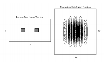
The complementary relationship between position and momentum required by the uncertainty principle is illustrated further in Figure 2, where the position and momentum distributions are shown for holes of dimension 0.5 a0. Clearly, the decreased localization in coordinate space has led to an increased localization in momentum space. Similar quantitative arguments relating the uncertainty principle to slit width and momentum distribution have recently been made in both the pedagogical [12] and research [13] literature for single-slit diffraction phenomena.

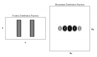
We can change the two holes to two slits by increasing the y dimension of the holes. For example, holding the x dimension constant at 0.3 a0 while increasing the y dimension to 1.5 a0 yields the diffraction pattern shown in Figure 3. This result is in agreement with the diffraction pattern obtained using the multislit mask on panel b of the Discovery Slide of reference 2. Comparing Figures 1 and 3, nothing has changed in the x direction, but the particle is partially delocalized in the y direction at the slit screen in Figure 3. According to the uncertainty principle, its momentum in the y direction will become more localized the spread in observed momentum values will decrease. To summarize, spatial localization leads to a delocalized momentum distribution that is projected onto the detection screen and is calculated as \( | \langle p | \Psi \rangle |^2 \) using eq 3. Furthermore, spatial localization at more than one position in a particular direction leads to interference effects in the momentum distribution in that direction.
It should also be pointed out that the double-slit experiment has been carried out at low source intensity such that there is only one particle in the apparatus at a time [14]. The resulting diffraction pattern is the same as that observed with intense sources; it just takes longer to record to the same number of observations. This confirms the quantum mechanical view that wave functions 1 and 2 represent individual particles rather than an ensemble of particles. According to quantum mechanical principles the particles can be placed in a well defined state by the slit screen, but the outcome of a subsequent measurement, momentum in this case, is not uniquely determined. All we can do is calculate the probability that a particular momentum state will be observed. The mechanism, therefore, is single-particle, or self-interference; two particles do not interfere with each other [14, 15].
With this introduction it is easy to move to a general treatment of diffraction by two-dimensional masks. Following eq 1, for a mask consisting of N scatterers the coordinate wave function is given by eq 4 below, and the momentum wave function is given by eq 3.
\[ | \Psi \rangle = \frac{1}{ \sqrt{N}} \sum_{i=1}^N | x_i,~y_i \rangle \nonumber \]
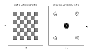
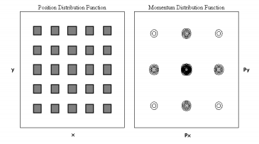
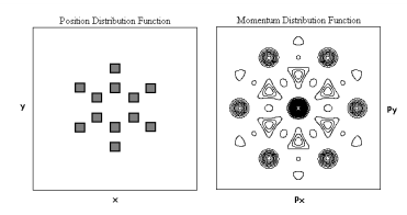
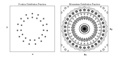
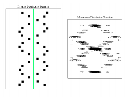
Figure 4 shows the diffraction pattern for a face-centered squaric arrangement of 25 holes (the two-dimensional analog of face-centered cubic), while Figure 5 was created with a simple squaric arrangement of 25 holes (the two-dimensional analog of simple cubic). Both calculated diffraction patterns are in excellent agreement with the experimental results shown in Figure 3a and b of reference 1. These examples show that the addition of a scatterer to the unit cell increases destructive interference and fewer momentum states are observed at the Figure 5. Hole dimensions are 0.5 a0 with horizontal and vertical detector.
Figures 6 and 7 show the calculated diffraction patterns for two concentric hexagons and two concentric pentadecagons, respectively. These calculated diffraction patterns are in excellent agreement with the experimental patterns found in Plates 10 and 12 in reference 5. Given the recently celebrated 50th anniversary of the publication of the DNA double helix structure [16] it is appropriate to draw special attention to references 3 and 4, which provide optical transforms that simulate DNA's experimental X-ray diffraction pattern.
Using the theoretical methods outlined above, it is possible to calculate in a rudimentary way several of the characteristic features of the DNA diffraction pattern. For example, representing DNA solely by a planar double strand of phosphate backbone groups as shown on the left side of Figure 8 generates the diffraction pattern shown on the right side. The essential features captured by this naive model are the characteristic X-shaped cross of the diffraction pattern and the missing fourth horizontal layer. Additional discussion on this rudimentary model is available in references 3 and 4.
The diffraction patterns presented in this paper have been calculated using Mathcad Plus 5.0. Naturally, once a calculation for one mask geometry has been programmed, it can serve as a template for other calculations with minor editing. Such a Mathcad file for calculating diffraction patterns for two-dimensional masks is available for download [17].
The conceptual and computational simplicity of the approach presented here makes it possible to bring experiment and theory together in the classroom in order to gain insight into the physical nature of diffraction phenomena from the quantum mechanical perspective.
Appendix A. The Fourier Transform
Wave-particle duality, as expressed by de Broglie's wave equation, is at the heart of quantum mechanics.
\[ \lambda = \frac{h}{p} \nonumber \]
On the left side we have the wave property, wavelength, and on the right momentum, the particle property; thus, (A.1) shows wave and particle properties in one equation united by the ubiquitous Planck's constant.
The most general coordinate-space wave function for a free particle with wavelength λ is the complex Euler function shown below in Dirac notation.
\[ \langle x | \lambda \rangle = exp \left( i \frac{2 pi x}{ \lambda} \right) \nonumber \]
Substitution of eq A.1 into eq A.2 yields the momentum wave function in the coordinate representation.
\[ \langle x | p \rangle = exp \left( \frac{ipx}{ \hbar} \right) \nonumber \]
The complex conjugate of eq A.3, \( \langle x | p \rangle = \langle p | x \rangle\), is the coordinate wave function in the momentum representation.
\[ \langle p|x \rangle = exp \left( - \frac{ipx}{ \hbar} \right) \nonumber \]
These equations are extremely useful in quantum mechanics in translating coordinate-space information into the momentum representation, and vice versa.
For example, if a system is in a well-defined state, \(| \Psi \rangle\), it might be expressed in coordinate language as \( \langle x | \Psi \rangle \) or momentum language as \( \langle p | \Psi \rangle \). If one is known, the other can be found by a Fourier transform because both representations contain the same state information. As shown below, the overlap integral between \( \langle x | \Psi \rangle \) and \( \langle p | x \rangle\) in coordinate space is the momentum wavefunction, and the overlap between \( p | \Psi \rangle\) and \( \langle x | p \rangle\) in momentum space is the position wavefunction.
\[ \langle p | \Psi \rangle = \int \langle p | x \rangle \langle x | \Psi \rangle dx = \frac{1}{ \sqrt{2 pi \hbar}} \int exp \left( - \frac{ipx}{ \hbar} \right) \Psi (x) dx \nonumber \]
\[ \langle x | \Psi \rangle = \int \langle x | p \rangle \langle p | \Psi \rangle dx = \frac{1}{ \sqrt{2 pi \hbar}} \int exp \left( - \frac{ipx}{ \hbar} \right) \Psi (p) dp \nonumber \]
In these equations \( (2 \pi \hbar )^{ - \frac{1}{2}}\) is the normalization constant for \( \langle x | p \rangle\) and \( \langle p | x \rangle\).
In our analysis of diffraction phenomena, eq A.5 is used because state preparation occurs in coordinate space at the slit screen yielding \( \langle x | \Psi \rangle\), which is then projected into momentum space, \( \langle p | \Psi \rangle\), to calculate the diffraction pattern, \( | \langle p | \Psi \rangle |^2\), at the detection screen.
Appendix B. Bragg's Law
The reader will have noticed that we only made brief mention of Bragg's Law in our presentation. This is because we prefer, for pedagogical reasons, Marcella's quantum mechanical approach with its roots in von Laue's early classical analysis of X-ray diffraction as a scattering phenomenon. The following quotation from French and Taylor's excellent text reveals the connection between von Laue and Bragg in the pre-quantum mechanical era [18].
The original analysis by von Laue treated the problem (X-ray diffraction), as basically one must, in terms of the scattering of an incident X-ray beam by all the individual atoms in the three-dimensional lattice making up the crystal. This is somewhat formidable, but very soon afterwards (in 1913), W. L. Bragg showed that the results of the analysis are the same as if one regarded the x-rays as being reflected at sets of parallel planes that include many atoms.
Reflection, therefore, is a conceptual device that simplifies analysis; diffraction is really a scattering phenomenon that behaves as if it were reflection for simple systems. While Bragg's approach simplifies analysis in simple cases, it does so at the expense of providing an incorrect physical picture of what is actually occurring. It has also led to abstract concepts such as the reciprocal lattice and Miller indices which students and teachers alike find difficult to understand. In our teaching we prefer the more direct appeal to the physical concepts of position and momentum, united as they always are by the uncertainty principle.
References and Notes
- Lisensky, G. C.; Kelly, T. F.; Neu, D. R.; Ellis, A. B. The Optical Transform: Simulating Diffraction Experiments in Introductory Courses. J. Chem. Educ. 1991, 68, 91-96.
- Lisensky, G. C.; Ellis, A. B.; Neu, D. R. Optical Transform Kit, 2nd Ed.; Institute for Chemical Education: University of Wisconsin, Madison, WI, 1994.
- Lucas, A. A.; Lambin, Ph.; Mairesse, R.; Mathot, M. Revealing the Backbone Structure of B-DNA from Laser Optical Simulations of Its 1 X-ray Diffraction Diagram. J. Chem. Educ. 1999, 76, 378ñ383.
- Lisensky, G. C.; Lucas A. A.; Nordell, K. J.; Jackelen, A. L.; Condren, S. M.; Tobe, R. H.; Ellis, A. B. DNA Optical Transform Kit; Institute for Chemical Education: University of Wisconsin, Madison, WI, 1999.
- Harburn, G.; Taylor, C. A.; Welberry, T. R. Atlas of Optical Transforms; Cornell University Press: Ithaca, NY, 1975.
- Marcella, T. V. Quantum interference with slits. Eur. J. Phys. 2002, 23, 615-621.
- Rioux, F. Calculating diffraction patterns. Eur. J. Phys. 2003, 24, N1-N3.
- Feynman, R. P.; Leighton, R. B.; Sands, M. The Feynman Lectures on Physics; Addison-Wesley: Reading, 1965; Vol 3.
- Feynman, R. P. The Character of Physical Law; MIT Press: Cambridge, 1967; p 130.
- Dirac bracket notation is used exclusively in this paper because it is a concise and coherent language in which to express quantum mechanical concepts. For further examples of its use see reference 8 or visit http://www.users.csbsju.edu/~frioux/dirac/dirac.pdf (accessed Dec 2003).
- Atomic units are used in these calculations: \( ( \hbar = m_e = e = 1)\). The atomic unit of distance is the bohr, a0. 1 a0 = 52.9 pm.
- Muino, P. L. Introducing the Uncertainty Principle Using Diffraction of Light Waves. J. Chem. Educ. 2000, 77, 1025-1027.
- Nairz, O.; Arndt, M.; Zeilinger, A. Experimental verification of the Heisenberg uncertainty principle for hot fullerene molecules. Phys. Rev. A. 2002, 65, 032109.
- Nairz, O.; Arndt, M.; Zeilinger, A. Quantum interference experiments with large molecules, Am. J. Phys. 2003, 71, 319-325.
- "Each photon then interferes only with itself. Interference between two different photons never occurs." From Dirac, P. A. M. The Principles of Quantum Mechanics, 4th ed.; Oxford University Press: Oxford, 1958, p 9.
- Watson, J. D.; Crick, F. H. C. Molecular Structure of Nucleic Acids: A Structure for Deoxyribose Nucleic Acid. Nature 1953, 171, 737.
- www.users.csbsju.edu/~frioux/...n/template.mcd (accessed Dec 2003).
- French, A. P.; Taylor, E. F. An Introduction to Quantum Physics; W. W. Norton & Co. Inc.: New York, 1978, p 41.

